Table of Contents
Advertisement
Advertisement
Table of Contents

Related Manuals for thomann harley Benton FXL8 Pro


Summary of Contents for thomann harley Benton FXL8 Pro
- Page 1 FXL8 Pro effects looper user manual...
- Page 2 Musikhaus Thomann e.K. Treppendorf 30 96138 Burgebrach Germany Telephone: +49 (0) 9546 9223-0 E-mail: info@thomann.de Internet: www.thomann.de 15.09.2014, ID: 337603...
-
Page 3: Table Of Contents
Table of contents Table of contents General information..........................4 1.1 Further information........................... 5 1.2 Notational conventions........................6 1.3 Symbols and signal words....................... 8 Safety instructions............................. 9 Features............................... 12 Installation..............................13 Connections and operating elements................... 20 Operating..............................27 Technical specifications........................39 Plug and connection assignment.................... -
Page 4: General Information
General information General information This manual contains important instructions for the safe operation of the unit. Read and follow the safety instructions and all other instructions. Keep the manual for future reference. Make sure that it is available to all those using the device. If you sell the unit please make sure that the buyer also receives this manual. -
Page 5: Further Information
General information 1.1 Further information On our website (www.thomann.de) you will find lots of further information and details on the following points: Download This manual is also available as PDF file for you to download. Use the search function in the electronic version to find the topics of Keyword search interest for you quickly. -
Page 6: Notational Conventions
General information 1.2 Notational conventions This manual uses the following notational conventions: Letterings The letterings for connectors and controls are marked by square brackets and italics. Examples: [VOLUME] control, [Mono] button. Displays Texts and values displayed on the device are marked by quotation marks and italics. Examples: ‘24ch’... - Page 7 General information Instructions The individual steps of an instruction are numbered consecutively. The result of a step is indented and highlighted by an arrow. Example: Switch on the device. Press [Auto]. ð Automatic operation is started. Switch off the device. Text input Text inputs that are carried out on the device are indicated by typewriter font.
-
Page 8: Symbols And Signal Words
General information 1.3 Symbols and signal words In this section you will find an overview of the meaning of symbols and signal words that are used in this manual. Signal word Meaning DANGER! This combination of symbol and signal word indicates an immediate dangerous situation that will result in death or serious injury if it is not avoided. -
Page 9: Safety Instructions
Safety instructions Safety instructions Intended use This device is intended to be used to integrate multiple effects devices into the signal path between instrument and amplifier. Different configurations can be stored. Use the device only as described in this user manual. Any other use or use under other operating conditions is con‐ sidered to be improper and may result in personal injury or property damage. - Page 10 Safety instructions Safety DANGER! Danger for children Ensure that plastic bags, packaging, etc. are disposed of properly and are not within reach of babies and young children. Choking hazard! Ensure that children do not detach any small parts (e.g. knobs or the like) from the unit.
- Page 11 Safety instructions NOTICE! External power supply The device is powered by an external power supply. Before connecting the external power supply, ensure that the input voltage (AC outlet) matches the voltage rating of the device and that the AC outlet is protected by a residual cur‐ rent circuit breaker.
-
Page 12: Features
Features Features The unit is ideal for use and switching of up to eight effects devices in your guitar setup. It is characterized by: two separately or jointly usable signal loops for up to four effects units premium footswitch with True Bypass function Option to store settings for loops in eight memory banks two programmable trigger (switching outputs) with which other audio devices can be controlled... -
Page 13: Installation
Installation Installation Unpack and carefully check that there is no transportation damage before using the unit. Keep the equipment packaging. To fully protect the device against vibration, dust and moisture during transportation or storage use the original packaging or your own packaging material suitable for transport or storage, respectively. - Page 14 Installation 8-channel mode with usage of the MIDI output effects looper...
- Page 15 Installation If your instrument is connected to the input [IN] and your amplifier to the output [LOOP2 OUT], eight effects processors can be looped into the signal path. In this example, the MIDI output controls an audio processor that is arranged behind the preamp in the signal path. FXL8 Pro...
- Page 16 Installation 8-channel mode without usage of the MIDI output effects looper...
- Page 17 Installation If your instrument is connected to the input [IN] and your amplifier to the output [LOOP2 OUT], eight effects processors can be looped into the signal path. In this example, an audio processor arranged behind the preamp in the signal path is controlled by a third device. FXL8 Pro...
- Page 18 Installation 2×4-channel mode effects looper...
- Page 19 Installation Connect your instrument to the input [IN] of the device and the effects input of your amplifier to output [LOOP1 OUT]. Connect the effects output of your amplifier to the input [LOOP2 IN] and the power stage of your amp to the output [LOOP2 OUT]. Connect the inputs, that can be used to control the effects on your amplifier to the programmable trigger outputs [TRIGGER T1], [TRIGGER T2].
-
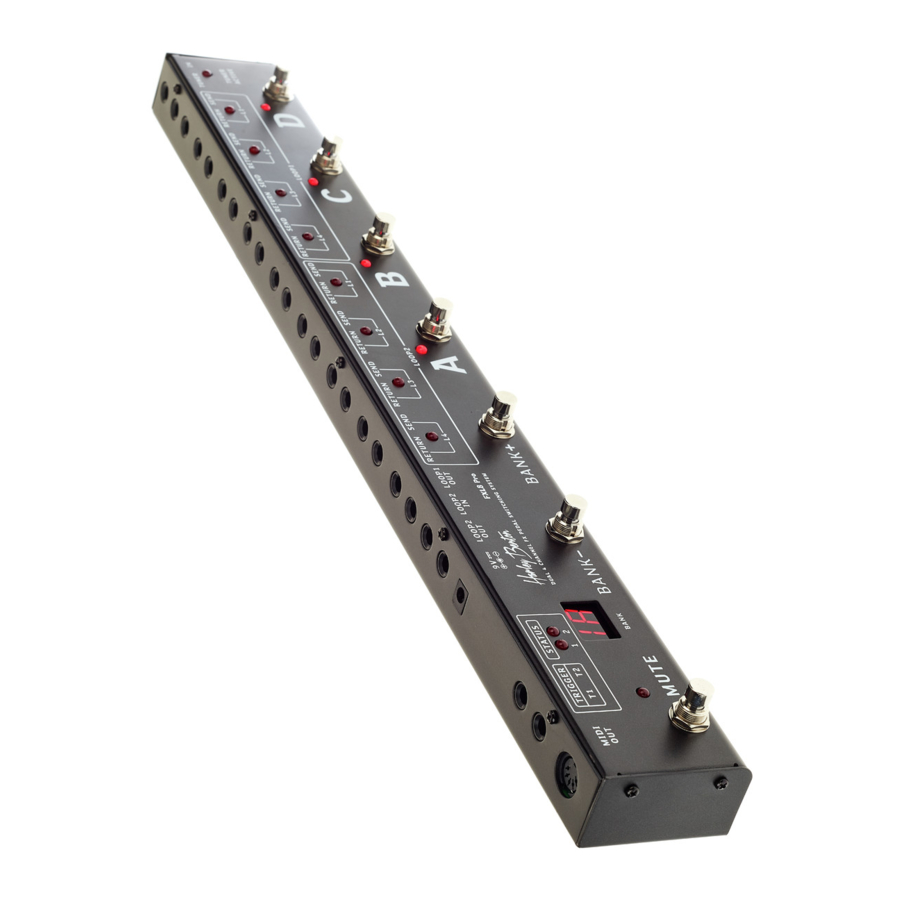
Page 20: Connections And Operating Elements
Connections and operating elements Connections and operating elements Top side effects looper... - Page 21 Connections and operating elements 1 [IN] Input socket. Connect here your instrument via a shielded cable with 1/4" phone plug. 2 [A], [B], [C], [D] The ‘True Bypass“ foot switches [A] to [D] turn the selected effects groups on or off. The corresponding control LED of the activated effects groups light up.
- Page 22 Connections and operating elements 6 [MUTE] Footswitch for operating mode selection. Press the foot switch successively to toggle between the operating modes ‘Mute’ (muted), ‘Tune’ (tuning), ‘Edit’ (programming mode) and ‘Normal’. The associated indicator LED is lit as long as the audio signal is not switched to the output.
- Page 23 Connections and operating elements 12 [LOOP2 IN] Loop input (signal loop) 2. 13 [LOOP1 OUT] Loop output (signal loop) 1. 14 [LOOP2 RETURN / SEND] Use these connectors to include up to four external effects devices into loop (signal loop) 2. Use shielded cables (1/4" plug) to connect each of the SEND sockets to the input of the effects unit and its output to the RETURN socket.
- Page 24 Connections and operating elements Rear panel effects looper...
- Page 25 Connections and operating elements 1 [IN] Input socket. Connect here your instrument via a shielded cable with 1/4" phone plug. 7 [MIDI OUT] Output for controlling a connected audio device with MIDI interface. 8 [TRIGGER T1], [TRIGGER T2] Output jacks for two programmable switching outputs. 10 [9V] Connection for the external voltage supply with 9 V DC.
- Page 26 Connections and operating elements 13 [LOOP1 OUT] Loop output (signal loop) 1. 14 [LOOP2 RETURN / SEND] Use these connectors to include up to four external effects devices into loop (signal loop) 2. Use shielded cables (1/4" plug) to connect each of the SEND sockets to the input of the effects unit and its output to the RETURN socket. A control LED is assigned to each channel.
-
Page 27: Operating
Operating Operating Control for tuner and mute When the device is not in edit mode, press [MUTE]. The unit activates the output [TUNER OUT] to which you can connect a tuner to tune your instrument. If you press [MUTE] again the outputs [LOOP1 OUT] and [LOOP2 OUT] are muted. You can tune your instrument without hearing the tones coming from the amp. - Page 28 Operating Using the edit function When the device is not in edit mode and the bypass is not active press [MUTE] for more than one second to enter the edit mode. The display then shows ‘EH’ , thus indicating that the edit mode was entered.
- Page 29 Operating Display Editing of ‘EP’ Polarity of Trigger 1 and 2: Refer to the manual of the device to be controlled by the trigger signals. ‘MA’ MIDI setting during patch status transition from ‘non-active’ to ‘active’. Refer to the manual of the device to be controlled by the MIDI interface. ‘MB’...
- Page 30 Operating Editing a loop combination When the device is in edit mode, press [BANK +] or [BANK –] until the display shows ‘EH’ (for Loop 2) or ‘EL’ (for Loop 1) (see Ä ‘Using the edit function’ on page 28). Since the operation is the same for both loops, only ‘EL’...
- Page 31 Operating Setting the Triggers To set the behaviour of the trigger, you should successively set polarity, operating mode, behaviour on active patch and behaviour on non-active patch. Experienced users can also directly select the relevant setting. Setting the Trigger polarity When the device is in edit mode, press [BANK +] or [BANK –] until the display shows ‘EP’...
- Page 32 Operating When the operating mode settings are complete, you can use [BANK +] or [BANK –] to skip to another subitem of the menu. When all settings are completed, press [MUTE] longer than one second to save the set‐ tings. To exit the edit mode without saving, press [MUTE] only briefly. Setting the action of Trigger 1 When the device is in edit mode, press [BANK +] or [BANK –] until the display shows ‘ET’...
- Page 33 Operating Now you can set how Trigger 1 and Trigger 2 work with non-activated patch (bypass) work. Here, ‘non-activated patch’ means that the effect channels assigned in a loop are switched off, resulting in a ‘clean’ signal path. Nevertheless, you can use the triggers to induce actions on another audio device, so for example, activate effects that are built into the amplifier.
- Page 34 Operating MIDI settings The device can send to sets of MIDI data (for example MIDI CC+ or MIDI CC+CC). To use the MIDI functions, the following sequence must be followed: Ex -> Ax -> Cx - Nx, where ‘x’ is 1 or 2, as in E1, A1, C1, N1 or E2, A2, C2, N2. To set the MIDI functions enter the edit mode first.
- Page 35 Operating Option Possible parameters E1: Message type of MIDI message 1 (MIDI message 1 message type) Turns the built-in MIDI controller off, the device does not send MIDI data. The device sends a ‘Program Change’ message. The device sends a ‘Control Change’ message. A1: Transmission channel of MIDI message 1 (MIDI message 1 transmit channel), available only if E1 is not equal to ‘OF’.
- Page 36 Operating Option Possible parameters 01…2.8 The displayed number represents the set value. For values from 100, the decimal point shifts. For example, value 128 is displayed as ‘2.8’ . When E1 is equal to ‘PC’, the number set for C1 represents one of 128 possible tones.
- Page 37 Operating Option Possible parameters 01…2.8 The displayed number represents the set value. For values from 100, the decimal point shifts. For example, value 128 is displayed as ‘2.8’ . When E1 is equal to ‘CC’, the number set for N1 represents the value passed by a ‘Control Change’...
- Page 38 Operating MIDI settings in MB section Section MB's MIDI settings let you trigger actions on the connected MIDI devices if the effects channels assigned to a loop are turned off and the signal path is ‘clean’. When the display shows ‘MB’ you can press [A] or [B] to successively call up options E1, A1, C1, N1, E2, A2, C2 and N2.
-
Page 39: Technical Specifications
Technical specifications Technical specifications Operating voltage supply (inner pole = minus) Current consumption 240 mA Dimensions (L × W × H) 541 mm × 67 mm × 53 mm Weight 1.68 kg FXL8 Pro... -
Page 40: Plug And Connection Assignment
Plug and connection assignment Plug and connection assignment Introduction This chapter will help you select the right cables and plugs to connect your valuable equip‐ ment in such a way that a perfect sound experience is ensured. Please note these advices, because especially in ‘Sound & Light’ caution is indicated: Even if a plug fits into the socket, an incorrect connection may result in a destroyed power amp, a short circuit or ‘just’... - Page 41 Plug and connection assignment Since the interference affects both cores equally, by subtracting the phase-shifted signals, the interfering signal is completely neutralized. The result is a pure signal without any noise inter‐ ference. 1/4" TS phone plug (mono, unbalanced) Signal Ground, shielding FXL8 Pro...
-
Page 42: Protecting The Environment
Protecting the environment Protecting the environment Disposal of the packaging mate‐ rial For the transport and protective packaging, environmentally friendly materials have been chosen that can be supplied to normal recycling. Ensure that plastic bags, packaging, etc. are properly disposed of. Do not just dispose of these materials with your normal household waste, but make sure that they are collected for recycling. - Page 44 Musikhaus Thomann e.K. · Treppendorf 30 · 96138 Burgebrach · Germany · www.thomann.de...
Need help?
Do you have a question about the harley Benton FXL8 Pro and is the answer not in the manual?
Questions and answers