Table of Contents
Advertisement
INSTALLATION AND OWNER GUIDE
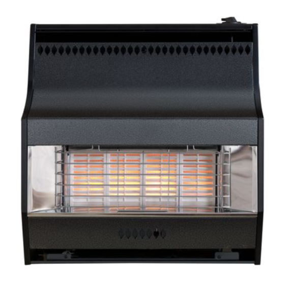
Model 347
RADIANT / CONVECTOR GAS FIRE
Fitted with the following fascia
Helmsley
We trust that this guide gives
sufficient details to enable this
appliance to be installed, operated
and maintained satisfactorily.
However, if further information is
required, our
Valor Fires Technical Helpline will
be pleased to help.
Telephone 0844 879 35 88 (National
call rates apply in the United
Kingdom).
In the Republic of Ireland
Telephone 01 842 8222.
INSTALLER: Please leave this guide with the owner
©
GDC Group Limited 2014.
08/52376/0
Advertisement
Chapters
Table of Contents

Related Manuals for Valor 347 Helmsley


Summary of Contents for Valor 347 Helmsley
- Page 1 However, if further information is required, our Valor Fires Technical Helpline will be pleased to help. Telephone 0844 879 35 88 (National call rates apply in the United Kingdom).
- Page 2 Warning: Any person who does any unauthorised act in relation to a copyright work may be liable to criminal prosecution and civil claims for damages. Valor Fires, GDC Group Ltd., Millbrook House, Hedge End, Southampton, SO30 2DF www.valor.co.uk Because our policy is one of constant development and improvement, details may vary slightly from those given in this publication.
- Page 3 BS EN ISO 9001 quality system accepted by the British Standards Institute. The Highest Standards Valor Fires is a member of SBGI and HHIC (Heating and Hot water Industry Council) that work to ensure high standards of safety, quality and performance. Careful Installation...
- Page 4 INSTALLER GUIDE INSTALLER GUIDE FOR OWNER GUIDE SEE PAGES 29 TO 44 © GDC Group Limited 2014. Page 4...
-
Page 5: Table Of Contents
INSTALLER GUIDE CONTENTS Section Heading Page INSTALLER GUIDE 4 - 28 OWNER GUIDE 29 - 43 1. SAFETY 2. LIST OF ACCESSORIES 3. APPLIANCE DATA AND EFFICIENCY 3.1 Appliance data. 3.2 Efficiency. 4. GENERAL INSTALLATION REQUIREMENTS 4.1 Regulations, Standards and Law. 4.2 Ventilation. -
Page 6: Installer Guide
INSTALLER GUIDE CONTENTS (Continued) Section Heading Page 7. CONTROL AND PRESSURE CHECKS 7.1 Check control settings. 7.2 Flame supervision and spillage monitoring system. 7.3 Check reference pressure. 8. FASCIA FITTING 9. SPILLAGE CHECK 10. FINAL REVIEW 11. SERVICING AND PARTS REPLACEMENT 11.1 To replace radiant(s). -
Page 7: Safety
INSTALLER GUIDE 1. SAFETY Installer Before continuing any further with the installation of this appliance please read the following guide to manual handling: The lifting weight of this appliance is 15.0 kg. One person should be sufficient to lift the fire. If for any reason this weight is considered too heavy then obtain assistance. -
Page 8: Appliance Data And Efficiency
Model Efficiency % (Gross) 347 Helmsley The gross calorific value of the fuel has been used for this efficiency calculation. The test data from which it has been calculated has been certified by Advantica Certification services (0087). The efficiency value may be used in the UK Government's Standard Assessment Procedure (SAP) for energy rating of dwellings. -
Page 9: General Installation Requirements
INSTALLER GUIDE 4. GENERAL INSTALLATION REQUIREMENTS 4.1 Regulations, Standards and Law. The installation must be in accordance with these instructions. For the user’s protection, in the United Kingdom it is the law that all gas appliances are installed by competent persons in accordance with the current edition of the Gas Safety (Installation and Use) Regulations. -
Page 10: Ventilation
INSTALLER GUIDE a) The current edition of IS 813 “Domestic gas installations”. b) All relevant national and local rules in force. c) The current building regulations. Where no specific instructions are given, reference should be made to the relevant British Standard Code of Practice. 4.2 Ventilation. -
Page 11: Fireplace Preparation
INSTALLER GUIDE 4.6 Fireplace preparation. 4.6.1 The appliance can be fitted to a purpose made proprietary class “O” 150°C surround. 4.6.2 If the fireplace opening is an underfloor draught type, it must be sealed to stop any draughts. 4.6.3 The front of the fireplace should be flat over an area sufficient to ensure a good seal with the closure plate. -
Page 12: Fireplace Clearances
INSTALLER GUIDE 4.7 Fireplace clearances. 4.7.1 The minimum allowable distance from the outside of the appliance fascia to a corner wall having combustible material or any other combustible surface which projects beyond the front of the appliance is 48mm at either side (See figure 2). Figure 2. -
Page 13: The Flue Spigot
250mm downwards measured from the bottom of the flue spigot (See figure 4). 4.8.2 A spigot extension is available (Valor Fires part number 0595191). When fitted this shall extend through the closure plate for at least 38mm and have a minimum clearance of 50mm from the end to any surface. -
Page 14: The Hearth
INSTALLER GUIDE 4.9. The hearth. The appliance must be mounted on a non-combustible hearth except when the conditions in section 4.10.3 are met (N.B. conglomerate marble hearths are considered as non-combustible). The hearth must be at least 680mm wide x 300mm deep. -
Page 15: Wall Mounting To Conventional Or Pre-Cast Flues
INSTALLER GUIDE The fireplace opening must be within the following dimensions: Precast flue Width Height Max. 440mm Max. 610mm Min. 305mm Min. 525mm The total height of the closure plate is 660mm and will accommodate a maximum opening height of 650mm (This allows a 10mm overhang). Heights above 620mm (Inclusive of sealing tape) will leave the sealing tape and closure plate visible above the appliance. -
Page 16: Metal Flue Box
INSTALLER GUIDE 4.10.4 Metal flue box. The appliance can be installed to a metal flue box conforming to BS 715 Section 6 (For gas fires to BS 7977-1) having a minimum internal depth of 165mm. The opening must be within the following dimensions: Metal Flue Box. -
Page 17: Pre-Installation Preparation
INSTALLER GUIDE accordance with BS 5440 Part 1 to ensure that the products of combustion can be safely dispersed into the outside atmosphere. Where the appliance is connected to an unlined brick chimney it is generally unnecessary for the chimney pot to be replaced or for a terminal to be fitted unless the flue has a diameter smaller than 170mm. -
Page 18: Fitting The Battery To Electronic Ignition Model
INSTALLER GUIDE 5.3 Fitting the battery to electronic ignition model. 1. At the front of the electronic spark generator there is a removable circular battery cover. Unscrew the cover in an anticlockwise direction. 2. Remove any protective film from the battery and place into the generator. The negative ( - ) terminal should go in first. -
Page 19: Fit The Closure Plate
INSTALLER GUIDE Fold Flange 2 along the perforated line. The closure plate has an opening at the bottom for a central gas feed pipe. The gap between the pipe and this opening should be sealed with tape after connection. If a central feed pipe is not required the opening should be completely sealed with tape. -
Page 20: Appliance Installation
INSTALLER GUIDE 6. APPLIANCE INSTALLATION 6.1 Installing to a hearth. 1. Place the fire centrally on the hearth making sure that the spigot lines up with the spigot hole in the closure plate. Gently slide the appliance into place being careful not to scratch the hearth. -
Page 21: Flue Restrictor Adjustment
INSTALLER GUIDE Generally we recommend the restrictor is NOT fitted where a precast flue is used, however, certain flues may work sufficiently to warrant its use. There may however, be circumstances where fitting the restrictor causes the fire to fail the spillage test. In such cases the restrictor will have to be re-opened. -
Page 22: Control And Pressure Checks
This monitoring system must not be adjusted, bypassed or put out of operation. This monitoring system, or any of its parts, must only be exchanged using Valor Fires authorised parts. © GDC Group Limited 2014. Page 22... -
Page 23: Check Reference Pressure
INSTALLER GUIDE 7.3 Check reference pressure. The appliance is pre-set to give the correct heat input at the inlet pressure shown in section 3 of this manual. No adjustment is necessary. 1. Ensure that the fire is turned OFF and detach the control knob from the spindle. Remove the fascia. -
Page 24: Spillage Check
INSTALLER GUIDE 9. SPILLAGE CHECK A spillage check must be made before leaving the installed appliance with the customer. Make this with all radiants and complete fascia in position. 1. Close all doors and windows in the room containing the fire. 2. -
Page 25: Final Review
INSTALLER GUIDE 10. FINAL REVIEW - COMPLETE THE INFORMATION IN THE WARRANTY AND SERVICE SECTION OF THE OWNER GUIDE (See last pages of the OWNER guide). - Make sure that the dress guard is securely in position. - Recheck the operation of the fire at all control positions. Explain to the customer that the appliance is fitted with a two-spark ignition system (See section 7.2 point 3). -
Page 26: Servicing And Parts Replacement
- Always test for gas soundness and spillage after servicing the appliance. 11.1 To replace radiant(s). Always use the correct type of replacement radiant. Ask for Valor Fires part number 5132071 (Single Radiant). Remove the dress guard by pressing down the two hooks at the top. Tilt the guard forward and lift out (See figure 14). -
Page 27: To Remove The Fascia
INSTALLER GUIDE Replace the dress guard. Locate the bottom of the dress guard in the two holes in the bottom panel apron. Push the guard back so that the two spring projections at the top of the guard engage in the slots under the front decorative canopy. 11.2 To remove the fascia. -
Page 28: To Remove The Complete Burner Module, Pipes And Pilot
INSTALLER GUIDE 11.4 To remove the complete burner module, pipes and pilot. 1. Remove the fascia as section 11.2. 2. Support the inlet ‘T’ connector to avoid straining the pipework and disconnect the appliance. 3. Disconnect the control spindle and adapter from the gas tap by removing the split pin. -
Page 29: Owner Guide
OWNER GUIDE OWNER GUIDE FOR WARRANTY AND SERVICE INFORMATION SEE PAGES 37 TO 44 © GDC Group Limited 2014. Page 29... - Page 30 OWNER GUIDE LIST OF CONTENTS Section Page SAFETY GAS CONSUMPTION APPLIANCE DIMENSIONS OPERATING YOUR FIRE The Oxysafe flame sensing and flue blockage safety system. To light the fire. CLEANING YOUR FIRE REPLACING THE RADIANTS MAINTENANCE Regular maintenance. WARRANTY AND SERVICE This gas fire is designed to meet the most stringent quality, performance and safety requirements to provide you with many years’...
-
Page 31: Safety
OWNER GUIDE SAFETY IF YOU SMELL GAS DON’T SMOKE. EXTINGUISH ALL NAKED FLAMES. DON’T TURN ELECTRICAL SWITCHES ON OR OFF. TURN OFF THE GAS SUPPLY AT THE METER. OPEN DOORS AND WINDOWS TO GET RID OF THE GAS. IMMEDIATELY CALL THE GAS EMERGENCY SERVICE FROM A NEIGHBOURS PHONE - SEE YOUR LOCAL TELEPHONE DIRECTORY. -
Page 32: Gas Consumption
OWNER GUIDE mind if ever you add a shelf. Do get advice about the suitability of any wall covering near your fire. Soft wall coverings (e.g. embossed vinyl, etc.) which have a raised pattern are easily affected by heat. They may, therefore, scorch or become discoloured when close to a heating appliance. -
Page 33: Appliance Dimensions
OWNER GUIDE APPLIANCE DIMENSIONS Figure 2. Dimensions and clearances OPERATING YOUR FIRE PLEASE NOTE When operating your fire for the first time, some vapours may be given off which may cause a slight odour and could possibly set off any smoke alarms in the immediate vicinity. -
Page 34: To Light The Fire
OWNER GUIDE To light the fire (Electronic ignition-Helmsley). The control is shown in figure 3. Depress the control knob slightly and turn anticlockwise towards the 1/IGN position. Do not apply too much pressure as this will cause resistance to be felt. Depress the control knob. -
Page 35: Cleaning Your Fire
REPLACING THE RADIANTS (See figure 5). Always use the correct type of replacement radiant. Ask for Valor Fires part number 5132071 (Single Radiant). Turn the fire off and allow it to cool before attempting to remove the radiants. -
Page 36: Maintenance
OWNER GUIDE MAINTENANCE Battery replacement (Electronic ignition). 1. The battery cover is located at the base of the fire on the right hand side. 2. Unscrew the battery cover in an anticlockwise direction. 3. Remove the battery and discard. 4. Remove any protective film from the replacement battery and place into the generator. -
Page 37: Warranty And Service
OWNER GUIDE WARRANTY AND SERVICE Standard Warranty Terms & Conditions The warranty is for 12 months subject to contract. In the United Kingdom servicing can be carried out either by a GDC service engineer or a GAS SAFE REGISTER engineer. Outside of the United Kingdom servicing can be carried out either by a CORGI or GAS SAFE REGISTER engineer. - Page 38 OWNER GUIDE When calling the GDC Helpline, it would be helpful if you could have the following information to hand:- Fire serial number and fascia code (The serial number can be found on the serial number label - See figure 6 on page 44).* Date of installation.* Your installer name and address details.* Fire make and model number.*...
- Page 39 OWNER GUIDE © GDC Group Limited 2014. Page 39...
- Page 40 OWNER GUIDE © GDC Group Limited 2014. Page 40...
- Page 41 OWNER GUIDE © GDC Group Limited 2014. Page 41...
- Page 42 OWNER GUIDE © GDC Group Limited 2014. Page 42...
- Page 43 OWNER GUIDE To be completed by installer: Installer Details (Block Capitals) Installer Name Gas Safe Register or Corgi Registration Number. Company Name. Company Address Company Telephone number Company Fax number © GDC Group Limited 2014. Page 43...
- Page 44 Fascia code - Can be found close to the information label (Block Capitals) A LABEL CONTAINING THE FASCIA CODE MAY HAVE BEEN PLACED INSIDE THE BOX. Brand (Please tick) Valor Wonderfire Other......Date of Installation Figure 6. © GDC Group Limited 2014.
Need help?
Do you have a question about the 347 Helmsley and is the answer not in the manual?
Questions and answers
What is the Knob at the bottom RH side under the serial number for?for
The knob on the bottom right side under the serial number of the Valor 347 Helmsley is the control knob. Its functions include:
- Igniting the pilot by generating sparks.
- Being held down for about ten seconds after the pilot lights to allow the flame sensing probe to warm up.
- Adjusting the heat level once the pilot is lit.
- Turning off the appliance by partially depressing and turning it clockwise to the 'OFF' position.
- Relighting the pilot after waiting at least three minutes.
This answer is automatically generated