
Related Manuals for Airwell AWSI-HGD009-N11


Summary of Contents for Airwell AWSI-HGD009-N11
- Page 1 HGD 009/012 DCI Series Indoor Units Outdoor Units AWSI-HGD009-N11 AWAU-YGD009-H11 AWSI-HGD012-N11 AWAU-YGD012-H11 REFRIGERANT R410A HEAT PUMP APRIL- 2012 SM HGD-009/012 1-A.1 GB Version:1...
- Page 2 LIST OF EFFECTIVE PAGES LIST OF EFFECTIVE PAGES Note: Changes in the pages are indicated by a “Revision#” in the footer of each effected page (when none indicates no changes in the relevant page). All pages in the following list represent effected/ non effected pages divided by chapters.
-
Page 3: Table Of Contents
TABLE OF CONTENTS Table of Contents INTRODUCTION ..........................1-1 PRODUCT DATA SHEET....................... 2-1 RATING CONDITIONS ........................3-1 OUTLINE DIMENSION ........................4-1 PERFORMANCE DATA ......................... 5-1 SOUND LEVEL CHARACTERISTICS ................... 6-1 ELECTRICAL DATA........................7-1 WIRING DIAGRAM......................... 8-1 REFRIGERATION DIAGRAMS ...................... 9-1 TUBING CONNECTIONS ....................... -
Page 4: Introduction
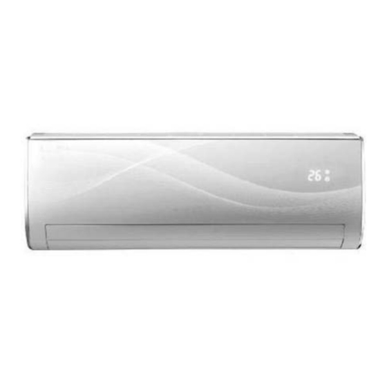
INTRODUCTION INTRODUCTION General HGD series is a monosplit DCI inverter air conditioner designed for residential buildings. The ODU YGD009/012 product is a DC inverter outdoor with high technology. By using DC compressor sine wave torque control technology, this product provides more comfort and economical operating. - Page 5 INTRODUCTION • Air sterilization- by Cold plasma that generating Active Hydrogen Oxygen and destory Bateria and Viruses. Indoor Unit The indoor unit is wall mounted, and can be easily fitted to many types of residential locations. It includes: • LED display •...
- Page 6 Flare type interconnecting tubing to be produced on site. For further details please refer to the Installation Manual. Inbox Documentation Each unit is supplied with its own installation, operation and remote control manuals. Matching Table INDOOR UNITS AWSI-HGD009-N11 AWSI-HGD012-N11 OUTDOOR UNITS AWAU-YGD009-H11 AWAU-YGD012-H11 SM HGD-009/012 1-A.1 GB...
-
Page 7: Product Data Sheet
PRODUCT DATA SHEET PRODUCT DATA SHEET HGD009 // YDD009 Model Indoor Unit HGD 009 Model Outdoor Unit YGD 009 Installation Method of Pipe Flared Characteristics Units Cooling Heating Capacity (4) 2.60(1.00-3.40) 2.87(0.60-3.80) Power input (4) 0.645(0.2-1.20) 0.695(0.16-1.25) EER (Cooling) or COP(Heating) (4) 4.01 4.11 Energy efficiency class... - Page 8 PRODUCT DATA SHEET HGD012 //YGD012 Model Indoor Unit HGD 012 Model Outdoor Unit YGD 012 Installation Method of Pipe Flared Characteristics Units Cooling Heating Capacity (4) 3.50(1.30-4.00) 3.81(0.90-4.30) Power input (4) 0.97(0.36-1.30) 1.055(0.34-1.36) EER (Cooling) or COP(Heating) (4) 3.61 3.61 Energy efficiency class 220-240 Power supply...
-
Page 9: Rating Conditions
RATING CONDITIONS RATING CONDITIONS Rating conditions in accordance with ISO 5151 and ISO 13253 (for ducted units). Cooling: Indoor: C DB 19 C WB Outdoor: 35 C DB Heating: Indoor: C DB Outdoor: 7 C DB 6 C WB Operating Limits R410A Indoor Outdoor... -
Page 10: Outline Dimension
OUTLINE DIMENSION OUTLINE DIMENSION Indoor: HGD009/012 Outdoor: YGD009 SM HGD-009/012 1-A.1 GB... - Page 11 OUTLINE DIMENSION Outdoor: YGD012 SM HGD-009/012 1-A.1 GB...
-
Page 12: Performance Data
PERFORMANCE DATA AND PRESSURE CURVES PERFORMANCE DATA HGD009 5.1.1 Cooling Capacity (kW) ID COIL ENTERING AIR DB/WB TEMPERATURE [C OD COIL ENTERING AIR DB TEMPERATURE [ DATA 22/15 24/17 27/19 29/21 32/23 80 - 110 % of nominal -10 - 20 80 - 105 % of nominal (protection range) 25 - 50 % of nominal... - Page 13 PERFORMANCE DATA AND PRESSURE CURVES 5.1.3 Heating Capacity (kW) ID COIL ENTERING AIR DB TEMPERATURE [C OD COIL ENTERING AIR DB/WB TEMPERATURE [ DATA 1.83 1.70 1.57 -15/-16 0.42 0.46 0.50 2.03 1.91 1.78 -10/-12 0.50 0.55 0.59 2.19 2.06 1.93 -7/-8 0.57...
-
Page 14: Pressure Curves
PERFORMANCE DATA AND PRESSURE CURVES 5.1.5 Pressure Curves Cooling 1400 Indoor 1300 DB/WB 1200 22/15 1100 24/17 1000 27/19 29/21 32/23 Outdoor DB Temperature 4.00 3.50 22/15 3.00 24/17 2.50 27/19 29/21 2.00 32/23 1.50 1.00 Outdoor DB Temperature SM HGD-009/012 1-A.1 GB... - Page 15 PERFORMANCE DATA AND PRESSURE CURVES Heating 3500 3250 Indoor DB 3000 2750 2500 2250 2000 1750 1500 1250 1000 Outdoor WB Temperature 4.00 3.50 Indoor DB 3.00 2.50 2.00 1.50 1.00 Outdoor WB Temperature SM HGD-009/012 1-A.1 GB...
- Page 16 PERFORMANCE DATA AND PRESSURE CURVES HGD012 5.2.1 Cooling Capacity (kW) ID COIL ENTERING AIR DB/WB TEMPERATURE [C OD COIL ENTERING AIR DB TEMPERATURE [ DATA 22/15 24/17 27/19 29/21 32/23 80 - 110 % of nominal -10 - 20 80 - 105 % of nominal (protection range) 25 - 50 % of nominal 3.38...
- Page 17 PERFORMANCE DATA AND PRESSURE CURVES 5.2.3 Heating Capacity (kW) ID COIL ENTERING AIR DB TEMPERATURE [C OD COIL ENTERING AIR DB/WB TEMPERATURE [ DATA 2.43 2.26 2.09 -15/-16 0.63 0.70 0.76 2.70 2.53 2.36 -10/-12 0.76 0.83 0.89 2.91 2.74 2.57 -7/-8 0.86...
- Page 18 PERFORMANCE DATA AND PRESSURE CURVES 5.2.5 Pressure Curves Cooling 1400 Indoor 1300 DB/WB 1200 22/15 1100 24/17 1000 27/19 29/21 32/23 Outdoor DB Temperature 6.00 5.50 5.00 22/15 4.50 24/17 4.00 27/19 29/21 3.50 32/23 3.00 2.50 2.00 Outdoor DB Temperature SM HGD-009/012 1-A.1 GB...
- Page 19 PERFORMANCE DATA AND PRESSURE CURVES Heating 4000 3750 Indoor DB 3500 3250 3000 2750 2500 2250 2000 1750 1500 Outdoor WB Temperature 7.00 6.50 6.00 Indoor DB 5.50 5.00 4.50 4.00 3.50 3.00 Outdoor WB Temperature SM HGD-009/012 1-A.1 GB...
-
Page 20: Sound Level Characteristics
SOUND LEVEL CHARACTERISTICS SOUND LEVEL CHARACTERISTICS Sound Pressure Level SM HDD/HED-009/012 1-A.1 GB... - Page 21 SOUND LEVEL CHARACTERISTICS Soud Pressure Level Spectrum (Measured as Figure 1) HGD009 Cooling HGD009 Heating Noise spectrum & NC Curves Noise spectrum & NC Curves NC65 NC65 NC60 NC60 NC55 NC55 NC50 NC50 NC45 NC45 NC40 NC40 NC35 NC35 NC30 NC30 NC25 NC25...
-
Page 22: Electrical Data
ELECTRICAL DATA ELECTRICAL DATA DATA MODEL MODEL YGD009 YGD009 YGD012 YGD012 To indoor Power Supply 1PH-220-240V-50Hz Max Current, A 6.5A 7.2A Circuit Breaker,A Power Supply Wiring No. X Cross Section 3x1.5 mm 3x1.5 mm Interconnecting Cable Model No. X Cross 4x1.5 mm 4x1.5 mm Section mm... -
Page 23: Wiring Diagram
WIRING DIAGRAM WIRING DIAGRAM WIRING DIAGRAM LEGEND LEGEND BN-BROWN BN-BROWN WH-WHITE WH-WHITE BU-BLUE BU-BLUE YE-YELLOW YE-YELLOW BK-BLACK BK-BLACK RD-RED RD-RED OG-ORANGE OG-ORANGE YE/GN-YELLOW/GREEN YE/GN-YELLOW/GREEN OCT-OUTDOOR COIL THERMISTOR OCT-OUTDOOR COIL THERMISTOR OAT-OUTDOOR AIR THERMISTOR OAT-OUTDOOR AIR THERMISTOR CTT-COMP. DISCHARGE THERMISTOR CTT-COMP. DISCHARGE THERMISTOR HGD009/012 HGD009/012 SM HGD-009/012 1-A.1 GB... - Page 24 WIRING DIAGRAMS YGD009 YGD012 SM HGD-009/012 1-A.1 GB...
-
Page 25: Refrigeration Diagrams
REFRIGERATION DIAGRAM REFRIGERATION DIAGRAMS HGD009 + YGD009 HGD012 + YGD012 SM HGD-009/012 1-A.1 GB... -
Page 26: Tubing Connections
TUBING CONNECTIONS TUBING CONNECTIONS When the outdoor unit is installed above the indoor unit an oil trap is required every 5m along the suction line at the lowest point of the riser. In case the indoor unit is installed above the outdoor, no trap is required. -
Page 27: Control System
CONTROL SYSTEM CONTROL SYSTEM CONTROL SYSTEM 11.1 11.1 Electronic Control Electronic Control 11.1.1 11.1.1 Abbreviations Abbreviations Abbreviation Definition Air Condition Building Management System System Power Compressor Top Temperature sensor DC Inverter Electronic Expansion Valve Heating Element Human Machine Interface Heat Sink Temperature sensor Hertz (1/sec) –... - Page 28 CONTROL SYSTEM When starting the compressor, or when conditions are varied due to the change of the room condition, the frequency must be initialized according to the ΔD value of the indoor unit and the Q value of the indoor unit. Q value: Indoor unit output determined from indoor unit capacity, air flow rate and other factors.
- Page 29 CONTROL SYSTEM 11.1.3.2 Frequency Changes Control Frequency change rate is 1 Hz/sec. 11.1.3.3 Minimum On and Off Time Prohibit to turn ON the compressor for 3 minutes after turning it off.(except during deicing protection) The compressor will not stop within 6 minutes regardless of room temperature changes (except during protection) 11.1.4 Indoor Fan Control...
-
Page 30: Fan Mode
CONTROL SYSTEM 11.1.4.1 Turbo Speed In COOL and HEAT mode (not available in AUTO, DRY, FAN mode), press the Turbo button, the super high fan speed is selected on Remote control and the indoor fan rotates at super high speed. 11.1.5 Outdoor Fan Control 11.1.5.1 OFAN Speed Type... -
Page 31: Heat Mode
CONTROL SYSTEM 11.3.1 Indoor Fan operation under Cool Mode Under cooling mode, the fan will operate at each manual setting fan speed. In AutoFan user setting, fan speed will be adjusted automatically according to the SPT and RAT, rerfer to 11.1.4 11.4 Heat Mode If RAT≤SPT+2, the unit will operate in heating mode. -
Page 32: Dry Mode
CONTROL SYSTEM Residual heat blowing function During heating, when the stopping condition for the compressor is reached, the compressor and the outdoor fan motor stop running while the louver moves to P2. The indoor fan will stop after running for 60s at low speed. 11.5 Auto Cool/Heat Mode In AUTO mode, the system selects the running mode (COOL/HEAT/FAN) automatically according... -
Page 33: Sleep Function
CONTROL SYSTEM If swing function has not been set after unit stating up: Under heating mode, the upper and lower louver will rotate to position P4. Under other modes, the upper and lower louver will rotate to position P7. If swing function has been set after unit stating up: Under heating mode, the up and down louver can be set to position: P2-P3-P4-P5-P6 Under other modes, the upper and lower louver can be set to position: P7-P6-P5-P4-P3 Auto swing setting... - Page 34 CONTROL SYSTEM The SPT will be adjusted according to following chart. Press either Sleep button or ON/OFF button can cancel the Sleep function. Sleep function will not be available in Auto mode or Fan mode. 11.10 I-Feel function I-Feel function maintains the room temperature by comparing the RCT on remote control. Pressing IFEEL button will enable the I-Feel function.
- Page 35 CONTROL SYSTEM 11.12.1 Indoor Coil Defrost Protection Conditions for Start Controlling Judge the controlling start with the ICT (Indoor Coil Temperature) after 6min from operation start. During cooling operation, the signals being sent from the indoor unit allow the operating frequency limitation and then prevent freezing of the indoor heat exchanger.
- Page 36 CONTROL SYSTEM Compressor will resume its original operation state when OCT≤53 C AND Comp OFF time≥3min If the unit stops as such protection for 6 times, it can not resume running automatically and display malfunction, it can resume by pressing ON/OFF. 11.12.4 Compressor over Heating Protection The Discharging temperature is used as the compressor’s internal temperature.
- Page 37 CONTROL SYSTEM 11.12.6.1 Deicing Starting Conditions The starting conditions must be made with the outdoor air temperature (OAT) and outdoor coil temperature (OCT). Under the conditions that the system is in heating operation, duration of successive heating operation is more than 45min, or accumulated heating time more than 90 min, the unit will enter the deicing mode after 3 min with either of following condition: OAT>5 OCT≤-2...
- Page 38 CONTROL SYSTEM module protective signal is detected, stop the unit with module protection immediately. If the module protection is resumed and compressor has stopped for 3min, the unit will be allowed to operate. If the module protection continuously occurs for 6 times, it should not be resumed automatically, it can resume by pressing ON/OFF.
- Page 39 CONTROL SYSTEM COOL INDICATOR 1. Lights up during specified operation mode (COOL/DRY/HEAT). DRY INDICATOR HEAT INDICATOR 2* 7 segments display In normal situation, the setting temperature is displayed. Shows outdoor temperature or indoor temperature when receiving the corresponding demand from controller. It resumes displaying setting temperature 5s later Shows the alarm code whenever there is an alarm.(Refer to Diagonostic part)
-
Page 40: Test Mode
CONTROL SYSTEM 11.15 Test Mode 11.15.1 Entering Test Mode Test mode(Mode of testing capacity) can be achieved through special remote control settings as following table depends on models Model Mode Settings of Remote control Operation of Remote Display (Shown on display) control (2*7 segments) Cooling... -
Page 41: Characteristics Of Sensor
CONTROL SYSTEM 11.16 Characteristics of sensor 11.16.1 RAT/OAT RAT/OAT R-T chart Temperature(C) 11.16.2 ICT/OCT ICT/OCT R-T Chart Temperature(C) SM HGD-009/012 1-A.1 GB 11-15... - Page 42 CONTROL SYSTEM 11.16.3 CTT R-T Chart Temperature(C) 11-16 SM HGD-009/012 1-A.1 GB...
-
Page 43: Troubleshooting
TROUBLESHOOTING TROUBLESHOOTING 12.1 ELECTRICAL & CONTROL TROUBLESHOOTING 12.1.1 Precautions before Performing Inspection or Repair Be cautious during installation and maintenance. Do operation following the regulations to avoid electric shock and casualty or even death due to drop from high attitude. * Static maintenance is the maintenance during de-energization of the air conditioner. - Page 44 TROUBLESHOOTING 12.1.3 Judgment by Indoor/Outdoor Unit Diagnostics If there is malfunction, error code will be shown from IDU display, and the outdoor LEDs blinking can also show the faults from ODU. Remark: ☆means LED Blink (☆ x 1 means blink once, and the LED blink: 0.5 second on, 0.5 second off, between two error cycles, it will be 2 seconds off interval.) means: LED OFF □...
- Page 45 TROUBLESHOOTING Reaching temperature ☆ x 8 point Too high ambient temperature ☆ x 13 Limit frequency(Over power) Poor heat exchange (including blockage and bad radiating environment ) ☆ x 14 Protection of fan Normal communication ☆ Wiring mistakes Communication malfunction □...
- Page 46 TROUBLESHOOTING 12.1.4 Checking the refrigeration system Checking system pressures and other thermodynamic measures should be done when system is in Test Mode (in Test mode, system operates in fixed settings). The performance curves given in this manual are given for unit performance in test mode when high indoor fan speed is selected.
-
Page 47: Exploded View & Spare Part List
EXPLODED VIEW & SPARE PART LIST EXPLODED VIEW & SPARE PART LIST 13.1 Exploded view of indoor unit: HGD009, HGD012 SM HGD-009/012 1-A.1 GB 13-1... - Page 48 EXPLODED VIEW & SPARE PART LIST 13.2 Spare part list of indoor Unit: HGD009 Part Code Part Description Front Panel Assy 30565133 Display Board 24252023 Screw Cover 20012631 Front Case Sub-Assy 11122134 Filter Sub-Assy 10512186 Guide Louver 2 1054202001 Shaft of Guide Louver 73012005 Crank 1521212201...
- Page 49 EXPLODED VIEW & SPARE PART LIST 13.3 Spare part list of indoor unit: HGD012 Part Code Part Description Front Panel Assy 30565133 Display Board 24252023 Screw Cover 20012631 Front Case Sub-Assy 11122134 Filter Sub-Assy 10512186 Guide Louver 2 1054202001 Shaft of Guide Louver 73012005 Crank 1521212201...
- Page 50 EXPLODED VIEW & SPARE PART LIST 13.4 Exploded view of outdoor unit: YGD009 13-4 SM HGD-009/012 1-A.1 GB...
- Page 51 EXPLODED VIEW & SPARE PART LIST 13.5 Spare part list of outdoor Unit: YGD009 Part Code Part Description 26233100 Small Handle 10333427 Axial Flow Fan 1501308502 Brushless DC Motor 0170310401 Motor Support 01253454 Top Cover Sub-Assy 01473009 Rear Grill 01113546 Condenser Assy 3900030804G Temperature Sensor...
- Page 52 EXPLODED VIEW & SPARE PART LIST 13.6 Exploded view of outdoor unit: YGD012 13-6 SM HGD-009/012 1-A.1 GB...
- Page 53 EXPLODED VIEW & SPARE PART LIST 13.7 Spare part list of outdoor Unit: YGD012 Part Code Part Description 015330124 Front Panel 01233034 Clapboard Sub-Assy 06123401 Drainage Connecter 0120391901P Chassis Sub-assy 39000310G Temperature Sensor 00103215 Compressor and Fittings 01713041 Valve Support 0130200404 Right Side Plate Assy 07100006...
- Page 54 APPENDIX APPENDIX SM HDD/HED-009/012 1-A.1 GB 13-1...