
Related Manuals for Airwell AWSI-HDD009-H11


Summary of Contents for Airwell AWSI-HDD009-H11
-
Page 1: Indoor Units
Indoor Units Outdoor Units AWSI-HDD009-H11 AWSI-HED009-H11 AWAU-YDD009-H11 AWSI-HDD012-H11 AWSI-HED012-H11 AWAU-YDD012-H11 REFRIGERANT R410A HEAT PUMP NOVEMBER – 2010 SM HDDHED 1-A.1 GB Version: 1... - Page 2 LIST OF EFFECTIVE PAGES LIST OF EFFECTIVE PAGES Note: Changes in the pages are indicated by a “Revision#” in the footer of each effected page (when none indicates no changes in the relevant page). All pages in the following list represent effected/ non effected pages divided by chapters.
-
Page 3: Table Of Contents
TABLE OF CONTENTS Table of Contents INTRODUCTION ....................1-1 PRODUCT DATA SHEET ..................2-1 RATING CONDITIONS ..................3-1 OUTLINE DIMENSIONS ..................4-1 PERFORMANCE DATA & PRESSURE CURVES ..........5-1 SOUND LEVEL CHARACTERISTICS ..............6-1 ELECTRICAL DATA ....................7-1 WIRING DIAGRAMS .....................8-1 REFRIGERATION DIAGRAMS ................9-1 10. TUBING CONNECTIONS ..................10-1 11. -
Page 4: Introduction
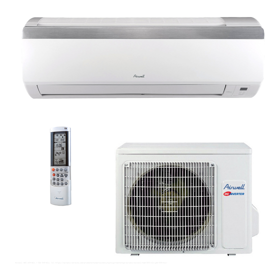
INTRODUCTION INTRODUCTION General HDD/HED series is a monosplit DCI inverter air conditioner designed for residential buildings. The ODU YDD009/012 product is a DC inverter outdoor with high technology. By using DC compressor sine wave torque control technology, this product provides more comfort and economical operating. The IDU HDD/HED-009/012 is a high-wall mounted type indoor with modern apperance. -
Page 5: Outdoor Unit
Flare type interconnecting tubing to be produced on site. For further details please refer to the Installation Manual. Inbox Documentation Each unit is supplied with its own installation, operation and remote control manuals. Matching Table INDOOR UNITS AWSI-HDD009-H11 AWSI-HDD012-H11 AWSI-HED009-H11 AWSI-HED012-H11 OUTDOOR UNITS √... -
Page 6: Product Data Sheet
PRODUCT DATA SHEET PRODUCT DATA SHEET HDD009 / HED009 // YDD 009 HDD/HED009 Model Indoor Unit YDD 009 Model Outdoor Unit Installation Method of Pipe Flared Characteristics Units Cooling Heating Capacity 0.45-3.23))2.65 0.45-4.1))3.52 Power input 0.2-1.35))0.8 0.2-1.45))0.95 EER (Cooling) or COP(Heating) 3.30 3.70 Energy efficiency class... - Page 7 PRODUCT DATA SHEET HDD012 / HED012 // YDD 012 HDD/HED012 Model Indoor Unit YDD 012 Model Outdoor Unit Installation Method of Pipe Flared Characteristics Units Cooling Heating Capacity 3.53(0.6-3.96) 4.1(0.6-5.13) Power input 1.1(0.22-1.45) 1.14(0.22-1.55) EER (Cooling) or COP(Heating) 3.21 3.61 Energy efficiency class 220-240 Power supply...
-
Page 8: Rating Conditions
RATING CONDITIONS RATING CONDITIONS Rating conditions in accordance with ISO 5151 and ISO 13253 (for ducted units). Cooling: Indoor: C DB 19 C WB Outdoor: 35 C DB Heating: Indoor: C DB Outdoor: 7 C DB 6 C WB Operating Limits 3.1.1 R410A Indoor... -
Page 9: Outline Dimensions
OUTLINE DIMENSIONS OUTLINE DIMENSIONS Indoor Unit: HDD009, HDD012, HED009, HED012 Outdoor Units: YDD009, YDD012 SM HDDHED 1-A.1 GB... -
Page 10: Performance Data & Pressure Curves
PERFORMANCE DATA & PRESSURE CURVES PERFORMANCE DATA HDD009, HED009 5.1.1 Cooling Capacity (kW) – Run Mode 230[V] : Indoor Fan at High Speed. ID COIL ENTERING AIR DB/WB TEMPERATURE [ OD COIL ENTERING AIR DB DATA 22/15 24/17 27/19 29/21 32/23 TEMPERATURE 80 - 110 % of nominal... - Page 11 PERFORMANCE DATA & PRESSURE CURVES 5.1.3 Heating Capacity (kW) - Run Mode 230[V] : Indoor Fan at High Speed. ID COIL ENTERING AIR DB TEMPERATURE [ OD COIL ENTERING AIR DB/WB DATA TEMPERATURE 2.20 2.05 1.89 -15/-16 0.58 0.64 0.70 2.45 2.30 2.14...
- Page 12 PERFORMANCE DATA & PRESSURE CURVES 5.1.5 Model: HDD009, HED009 5.1.5.1 Cooling 1400 Indoor 1300 DB/WB 1200 22/15 1100 24/17 1000 27/19 29/21 32/23 Outdoor DB Temperature 6.00 5.50 5.00 22/15 4.50 24/17 4.00 27/19 29/21 3.50 32/23 3.00 2.50 2.00 Outdoor DB Temperature SM HDDHED 1-A.1 GB...
- Page 13 PERFORMANCE DATA & PRESSURE CURVES 5.1.5.2 Heating 4000 3750 Indoor DB 3500 3250 3000 2750 2500 2250 2000 1750 1500 Outdoor WB Temperature 7.00 6.50 6.00 Indoor DB 5.50 5.00 4.50 4.00 3.50 3.00 Outdoor WB Temperature SM HDDHED 1-A.1 GB...
- Page 14 PERFORMANCE DATA & PRESSURE CURVES HDD012, HED012 5.2.1 Cooling Capacity (kW) - Run Mode 230[V] : Indoor Fan at High Speed. ID COIL ENTERING AIR DB/WB TEMPERATURE [ OD COIL DATA ENTERING AIR DB 22/15 24/17 27/19 29/21 32/23 TEMPERATURE [ 80 - 110 % of nominal -10 - 20 80 - 105 % of nominal...
- Page 15 PERFORMANCE DATA & PRESSURE CURVES 5.2.3 Heating Capacity (kW) - Run Mode 230[V] : Indoor Fan at High Speed. ID COIL ENTERING AIR DB TEMPERATURE [ OD COIL ENTERING AIR DB/WB DATA TEMPERATURE 2.56 2.38 2.20 -15/-16 0.71 0.78 0.85 2.85 2.67 2.49...
- Page 16 PERFORMANCE DATA & PRESSURE CURVES 5.2.5 Model: HDD012, HED012 5.2.5.1 Cooling 1400 Indoor 1300 DB/WB 1200 22/15 1100 24/17 1000 27/19 29/21 32/23 Outdoor DB Temperature 6.00 5.50 5.00 22/15 4.50 24/17 4.00 27/19 29/21 3.50 32/23 3.00 2.50 2.00 Outdoor DB Temperature SM HDDHED 1-A.1 GB...
- Page 17 PERFORMANCE DATA & PRESSURE CURVES 5.2.5.2 Heating 1400 1400 Indoor Indoor 1300 1300 DB/WB DB/WB 1200 1200 22/15 22/15 1100 1100 24/17 24/17 1000 1000 27/19 27/19 29/21 29/21 32/23 32/23 Outdoor DB Temperature Outdoor DB Temperature 6.00 6.00 5.50 5.50 5.00 5.00...
-
Page 18: Sound Level Characteristics
SOUND LEVEL CHARACTERISTICS SOUND LEVEL CHARACTERISTICS Sound Pressure Level Figure 1. Wall Mounted Sound Pressure Level Spectrum (Measured as Figure 1) HDD009 / HED009 HDD012 / HED012 SM HDDHED 1-A.1 GB... - Page 19 SOUND LEVEL CHARACTERISTICS Outdoor units Fig.2 Microphone Distance from Unit Sound Pressure Level Spectrum (Measured as Figure 2) YDD009/YDD012 Cooling YDD009/YDD012 Heating SM HDDHED 1-A.1 GB...
-
Page 20: Electrical Data
ELECTRICAL DATA ELECTRICAL DATA Single Phase Units MODEL YDD009 YDD012 To indoor Power Supply 1PH / 220-240V / 50Hz Max Current, A Circuit Breaker,A 16.0 16.0 Power Supply Wiring No. X Cross 3x1.5 mm 3x1.5 mm Section mm Interconnecting Cable RC 4x1.5 mm 4x1.5 mm Model No. -
Page 21: Wiring Diagrams
WIRING DIAGRAMS WIRING DIAGRAMS Indoor Units: HDD009, HDD012, HED009, HED012 Outdoor Units: YDD009, YDD012 SM HDDHED 1-A.1 GB... -
Page 22: Refrigeration Diagrams
REFRIGERATION DIAGRAMS REFRIGERATION DIAGRAMS HDD009 / HED009 // YDD009 HDD012 / HED012 // YDD012 SM HDDHED 1-A.1 GB... -
Page 23: Tubing Connections
TUBING CONNECTIONS TUBING CONNECTIONS TUBE (Inch) ¼” ⅜” ½” ⅝” ¾” TORQUE (Nm) Flare Nuts 11-13 40-45 60-65 70-75 80-85 Valve Cap 13-20 13-20 18-25 18-25 40-50 Service Port Cap 11-13 11-13 11-13 11-13 11-13 Valve Protection Cap-end Refrigerant Valve Port (use Allen wrench to open/close) Valve Protection Cap Refrigerant Valve Service Port Cap... -
Page 24: Control System
CONTROL SYSTEM CONTROL SYSTEM 11.1 Electronic Control 11.1.1 Abbreviations Abbreviation Definition Air Condition Building Management System System Power Compressor Top Temperature sensor DC Inverter Electronic Expansion Valve Heating Element Human Machine Interface Heat Sink Temperature sensor Hertz (1/sec) – electrical frequency Indoor Coil Temperature (RT2) sensor Indoor Unit Micro Controller Unit... - Page 25 CONTROL SYSTEM When the ΔD value is small- decrease the frequency When the ΔD value is large- increase the frequency 3. Frequency management when other controls are functioning When frequency is drooping; Frequency management is carried out only when the frequency droops. For limiting lower limit Frequency management is carried out only when the frequency rises.
-
Page 26: Indoor Fan Control
CONTROL SYSTEM 11.1.4 Indoor Fan Control 8 Indoor fan speeds are determined for each model. 4 speeds for COOL modes and 4 speeds for HEAT mode. Unit Model Mode Turbo(Super high) High Medium Cooling 1300 1100 Heating 1300 1140 Cooling 1350 1150 Heating... -
Page 27: Heat Mode
CONTROL SYSTEM SPT-2 >=6min >=3min >=6min COMP OFAN IFAN 11.3.1 Indoor Fan operation under Cool Mode When SPT-RAT<0, if indoor fan motor operates at high speed, the fan motor will operate at medium speed. The medium speed or low speed will be maintained; (this condition should be executed when compressor starts up);... -
Page 28: Dry Mode
CONTROL SYSTEM 11.5 Auto Cool/Heat Mode In AUTO mode, the system selects the running mode (COOL/HEAT/FAN) automatically according to the room temperature. The display shows the actual running mode and setting temperature. There will be 30s delay for mode conversion. When RAT≥25 C, the cooling mode is selected. -
Page 29: Sleep Function
CONTROL SYSTEM Clean function is defaulted as OFF after unit is Power ON. Clean function is not available in Auto, Fan or Heat mode. 11.9 Sleep function Pressing SLEEP button will enable the Sleep function. will be shown on remote control. Sleep function in Cool and Dry mode: The SPT will be adjusted according to following chart. - Page 30 CONTROL SYSTEM 11.11.1 Indoor Coil Defrost Protection Conditions for Start Controlling Judge the controlling start with the ICT (Indoor Coil Temperature) after 2 sec from operation start. During cooling operation, the signals being sent from the indoor unit allow the operating frequency limitation and then prevent freezing of the indoor heat exchanger.
- Page 31 CONTROL SYSTEM 11.11.5 Outdoor Coil Deicing Protection This protection is for Heat Pump Only This protection is carried out by the cooling cycle (reverse cycle). The defrosting time or outdoor heat exchanger temperature must be more than its setting values when finishing the deicing protection.
- Page 32 CONTROL SYSTEM 11.13 Indoor Unit Controllers and Indicators The following is schematic drawing for the display: RUN INDICATOR Lights up when the Air Conditioner is connected to power and the mode is STBY. When the unit is turned on remotely, the RUN LED goes out while the current setting running mode is displayed COOL INDICATOR Lights...
-
Page 33: Test Mode
CONTROL SYSTEM 11.14 Test Mode 11.14.1 Entering Test Mode Test mode(Mode of testing capacity) can be achieved through special remote control settings as following table depends on models: Settings of Remote control Mode Operation of Display Model (Shown on display) Remote control (2*7 segments) Cooling... - Page 34 CONTROL SYSTEM 11.15.2 ICT / OCT ICT/OCT R-T Chart Temperature(C) 11.15.3 RAT/OAT R-T chart Temperature(C) SM HDDHED 1-A.1 GB 11-11...
-
Page 35: Troubleshooting
TROUBLESHOOTING TROUBLESHOOTING 12.1 ELECTRICAL & CONTROL TROUBLESHOOTING 12.1.1 Precautions before Performing Inspection or Repair Be cautious during installation and maintenance. Do operation following the regulations to avoid electric shock and casualty or even death due to drop from high attitude. * Static maintenance is the maintenance during de-energization of the air conditioner. - Page 36 TROUBLESHOOTING 2* 7 LEDs Failure Possible Reasons segments RUN LED- OFF 3s and blink 2 Indoor Coil Defrost Protection Poor air-return in indoor unit times Fan speed is abnormal Evaporator is dirty. RUN LED-OFF 3s and blink 4 Compressor over Heating connectgion problem times...
- Page 37 TROUBLESHOOTING 2* 7 LEDs Failure Possible Reasons segments HEAT LED- OFF 3s and blink HST failure Senor was broken or damaged 18 times PCB temperature detection cuircuit has problem HEAT LED- OFF 3s and blink HST overheating protection Insufficient attachment 19 times module to Heatsink Outdoor PCB problem.
- Page 38 TROUBLESHOOTING 12.1.4 Checking the refrigeration system Checking system pressures and other thermodynamic measures should be done when system is in Test Mode (in Test mode, system operates in fixed settings). The performance curves given in this manual are given for unit performance in test mode when high indoor fan speed is selected.
-
Page 39: Exploded Views And Spare Parts Lists
EXPLODED VIEWS AND SPARE PARTS LISTS EXPLODED VIEWS AND SPARE PARTS LISTS 13.1 Indoor Unit: HDD009, HED009 SM HDDHED 1-A.1 GB 13-1... - Page 40 EXPLODED VIEWS AND SPARE PARTS LISTS 13.2 Indoor Unit: HDD009, HED009 Part Code Part Description 20192439 Decorative Strip 20012806 Front Panel 20012823 Front Panel Assy 1112208201 Filter Sub-Assy 24252019 Screw Cap 20012824 Front Case Assy 10512160 Air Louver 26112486 Helicoid tongue 2220211901_K46462 Rear Case assy 76712020...
- Page 41 EXPLODED VIEWS AND SPARE PARTS LISTS 13.3 Indoor Unit: HDD012, HED012 SM HDDHED 1-A.1 GB 13-3...
- Page 42 EXPLODED VIEWS AND SPARE PARTS LISTS 13.4 Intdoor Unit: HDD012, HED012 Part Code Part Description 20192439 Decorative Strip 20012806 Front Panel 20012823 Front Panel Assy 1112208201 Filter Sub-Assy 24252019 Screw Cap 20012824 Front Case Assy 10512160 Air Louver 26112486 Helicoid tongue 2220211901_K46462 Rear Case assy 76712020...
- Page 43 EXPLODED VIEWS AND SPARE PARTS LISTS 13.5 Outdoor Unit: YDD009, YDD012 SM HDDHED 1-A.1 GB 13-5...
- Page 44 EXPLODED VIEWS AND SPARE PARTS LISTS 13.6 Outdoor Unit: YDD009 Part Code Part Description 22413018 Front Grill 01433418P Cabinet 15013073 Fan Motor 0010376101 Compressor and fittings 00181067 Overload Protector 0120390901P Chassis Sub-assy 1033300901 Axial Flow Fan Sub-Assy 0170311101 Motor Support 01233088 Clapboard 01713089...
- Page 45 EXPLODED VIEWS AND SPARE PARTS LISTS 13.7 Outdoor Unit: YDD012 Part Code Part Description 22413018 Front Grill 01433418P Cabinet 15013073 Fan Motor 0010376101 Compressor and fittings 00181067 Overload Protector 0120390901P Chassis Sub-assy 1033300901 Axial Flow Fan Sub-Assy 01703111 Motor Support 01233088 Clapboard 01713089...
-
Page 46: Appendix A
APPENDIX A APPENDIX A INSTALLATION AND OPERATION MANUAL ► OPERATING MANUAL HDD/HED009-012 ► INSTALLATION MANUAL HDD/HED009-012 14-1 SM HDDHED 1-A.1 GB...
Need help?
Do you have a question about the AWSI-HDD009-H11 and is the answer not in the manual?
Questions and answers