Table of Contents
Advertisement
Quick Links
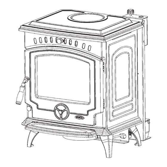
Tara Oil Stove
MK 3
INSTALLATION AND OPERATION INSTRUCTIONS
This appliance is hot while in operation and retains its heat for a long period of time after use. Children,
aged or infirm persons should be supervised at all times and should not be allowed to touch the hot
working surfaces while in use or until the appliance has thoroughly cooled.
Advertisement
Table of Contents

Related Manuals for Stanley Tara Mk3


Summary of Contents for Stanley Tara Mk3
- Page 1 Tara Oil Stove MK 3 INSTALLATION AND OPERATION INSTRUCTIONS This appliance is hot while in operation and retains its heat for a long period of time after use. Children, aged or infirm persons should be supervised at all times and should not be allowed to touch the hot working surfaces while in use or until the appliance has thoroughly cooled.
-
Page 2: Table Of Contents
TABLE OF CONTENTS Page No. Introduction ............3 Stove Dimensions . -
Page 3: Introduction
Installation should be carried out in a well ventilated area. Any alterations to this appliance that are not approved in writing by Waterford Stanley will render the guarantee void. This appliance is hot while in operation and retains its heat for a long period of time after use. Children, aged or infirm persons should be supervised at all times and should not be allowed to touch the hot working surfaces while in use or until the appliance has thoroughly cooled. -
Page 4: Stove Dimensions
STOVE DIMENSIONS TECHNICAL DATA Fuel: Kerosene 28 sec (Class C2) Mains Current: 220V - 240V, 50Hz, A.C. Supply Fuse Rating: 3 amp Chimney Draught: 12 Pa Flue Diameter: 5” (125 mm) Max Flow Rate 15cc / min Min Flow Rate 5cc / min Max Permitted Flow Rate 15.5cc/min... -
Page 5: Installation
INSTALLATION The installation must be completed in accordance with current National and European Standards and Local Codes. It should be noted that the requirements and these publications may be superceded during the life of this manual. B.S. 5410 Part 1 Oil Installations The Building Regulations: Part J England, Wales. -
Page 6: Flue Supply/Installation Oil Storage Tanks
FUEL SUPPLY / INSTALLATION locks. Exposed lengths of oil supply pipe must be OIL STORAGE TANKS: properly supported by purpose made clips securely fixed in place. Metal clips formed so as to hold the Oil storage tanks made of steel and all connecting pipe on to a saddle are preferred. -
Page 7: Clearance To Combustible Material
Fig.6 These requirements are in accordance with the fol- lowing relevant sections of BS 5410: Part 1 O.F.S. A105 Oil Stove Standard. The Building Regulations for Scotland, Ireland, Northern Ireland, England & Wales. NOTE: Fuel to the appliance should be gravity fed only. -
Page 8: The Flue
Fig.8 IMPORTANT NEVER OBSTRUCT FREE AIR CIRCULATION AROUND SIDES, BACK, TOP, UNDERNEATH, AND FRONT OF STOVE, EVEN IF IT IS INSTALLED AGAINST NON-COMBUSTIBLE WALLS. NEVER BUILD STOVE INTO FIREPLACES ETC..IF AIR FLOW IS RESTRICTED AROUND THE STOVE, THE REMOTE ACTING FIRE VALVE PHIAL WILL OVER-HEAT AND SHUT OFF THE OIL SUPPLY. -
Page 9: Use Of Internal Flues Or Chimneys
3. The flue liner should be of 125mm (5”) diameter Fig.10 rigid or flexible (preferably rigid) stainless steel Rear Flue Outlet Top Flue Outlet class 1 or class 2 flue liner that complies with B.S. 4543 Part 1 & 3). 4. -
Page 10: Flue Termination Height
FLUE STABILISER 3. The flue pipe should be of 125mm (5”) diame- ter rigid insulated stainless steel pipe, that con- The stove is fitted with a flue stabiliser (See Fig.11), forms to B.S. 4543 and B.S. 5410. which will help to ensure a stable draught is main- tained through the stove when the flue is subjected to 4. -
Page 11: Installation Assembly
The effective area of any vent should be ascertained If you choose to purchase the optional heat- before installation. The effect of any screen should shield, Insert it underneath the stove aligning the be allowed for when determining the effective free tabs on the back of the heathshield with the slots area of any vent. -
Page 12: Commissioning
Fig.19 Fig.18 3. Check the control valve rating, see section on Control Valve Rating below. 4. When the stove reaches its normal operating temperature (i.e. at maximum setting), adjust the Fig.18A draught regulator until the desired flame pattern is achieved. 5. - Page 13 2. Place the collection vessel beneath the inlet pipe to catch the oil. Turn the control valve to 6 and start the stopwatch when the first drop of oil falls into the vessel. 3. Measure the oil flow for 5 minutes (Consult the Technical Data section for the correct rate).
-
Page 14: Exploded View
TARA EXPLODED VIEW 29. AIR WASH KNOB - U00077AXX 30. TERRY CLIP - W00921AXX COMBUSTION CHAMBER - F01087AXX 31. ISOLATING TRANSFORMER - G00506AXX LEG (LONG) - B00007BZZ 32. STRAIN RELIEF CABLE GLAND - V00961AXX FRONT PANEL - B00257JXX 33. TRANSFORMER COVER - F01134AXX SIDE PANEL - B00211BZZ... -
Page 15: Stove Operation
Remove any soot deposit on the glass with a soft dry NOTE: THE STOVE MUST BE COMMISSIONED cloth when the glass is cold, minor deposits on the BY AN AUTHORISED STANLEY SERVICE AGENT PRIOR TO THE FIRST OPERATION. -
Page 16: Turning The Stove Off
glass may only become evident when the flame is SERVICING viewed through the glass. NOTE: ALL WORK SHOULD BE CARRIED OUT WHEN THE STOVE IS COOL AND THE OIL In certain circumstances it may be necessary to SUPPLY IS TURNED OFF. prime the flue see previous sections on “flue draught”... -
Page 17: Fire Safety
CO ALARM embers. 3. A practical evacuation plan. Waterford Stanley recommend the fitting of a CO Alarm in the same room as the appliance. 4. A plan to deal with a chimney fire as follows:- Further guidance on the installation of a carbon monoxide alarm is available in BS EN 50292:2002 (a) Notify the fire department. -
Page 18: Vitreous Enamel Cleaning
VITREOUS ENAMEL CLEANING General cleaning must be carried out when the stove is cool. If the stove is finished in a high gloss vitreous enamel, to keep the enamel in the best condition observe the following tips: 1. Wipe over daily with a soapy damp cloth, followed by a polish with a clean dry duster. -
Page 19: Fault Finding
FAULT FINDING If the stove exhibits any of the following conditions, call your commissioning engineer. SYMPTOM POSSIBLE CAUSES REMEDY Stove will not light No electrical supply to the Check Plug Top Fuse or connec- stove tor block fuse. No Oil in tank Fill Tank Manual or fire valves off Open or reset valves. - Page 20 Manufactured by Waterford Stanley Ltd., Unit 401-403, IDA Industrial Estate, Cork Road, Waterford, Ireland. Tel: (051) 302300 Fax (051) 302315 www.waterfordstanley.com DP 160104 Rev:002 N00557AXX...
Need help?
Do you have a question about the Tara Mk3 and is the answer not in the manual?
Questions and answers