Sign In
Upload
Manuals
Brands
Micros Systems Manuals
Desktop
PCWS 2015
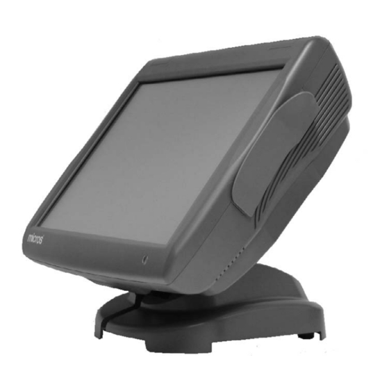
Micros Systems PCWS 2015 Manuals
Manuals and User Guides for Micros Systems PCWS 2015. We have
1
Micros Systems PCWS 2015 manual available for free PDF download: Setup Manual
Micros Systems PCWS 2015 Setup Manual (178 pages)
Brand:
Micros Systems
| Category:
Desktop
| Size: 9 MB
Table of Contents
Printing History
2
Table of Contents
3
Preface
10
Why Read this Manual
10
Purpose
10
How this Manual Is Organized
11
Notation Conventions
12
Symbols
12
Document Design and Production
12
Chapter 1 : What Is the PCWS 2015
14
The System
14
Operator Features
14
15" TFT LCD and Resistive Touchscreen
14
Operator LED
15
Power Button
15
3-Track Magnetic Card Reader
15
Cooling System
15
Internal Speakers
15
Mass Storage
16
2.5" SATA Drive Bay
16
Eusb Flash Drive
17
Compact Flash Card
17
Memory Expansion
17
AC Input
18
IO Door
18
Vesa 100
18
Features
19
Expansion Capabilities
19
Serial Ports
19
USB Ports
19
Type a USB Ports
19
Powered USB Ports
19
System Board USB Headers
20
USB Port Security
20
Mini-PCI Socket
21
Workstation Mounting Options
22
The Adjustable Stand
22
Power Supply Compartment
23
LCD Customer Display Options
24
240X64 LCD Customer Display
24
Protege LCD Customer Display System
25
Software Platform
26
Bios
26
Operating Systems
26
PCWS API and MICROS OPOS Drivers
26
PCWS 2015 Diagnostics Utility
26
Micros Cal32
27
Simphony Prerequisite Software
27
POS Application
27
Intel AMT
27
Power Management States
28
Introduction
28
Unplugged
28
Nopower
28
Standby and Hibernate
28
Last Power State Retention
28
PCWS 2015 Power Management Table
29
Specifications
30
Approvals
31
Chapter 2 : PCWS 2015 BIOS
34
PCWS 2015 BIOS Version and System Board Compatibility
34
System Board Revision C
34
System Board Revision D
34
Starting the BIOS Setup Utility
34
Starting BIOS Setup Utility
34
System Information Screen
36
BIOS Version and Build Time
36
Processor Type and Speed
36
System Memory Speed
37
L2 Cache RAM
37
Memory Mode
37
Memory Channel a Slot 0
37
Memory Channel B Slot 0
37
Advanced
38
Select Language
38
Boot Configuration
39
ACPI Configuration
41
Processor Configuration
43
HDD Configuration
46
IMC Configuration
48
South Bridge Configuration
51
Network Configuration
56
Winbond Configuration
57
Special Configuration
58
AMT Configuration
60
ME Configuration
62
Security
63
Boot
65
Exit
67
Chapter 3 : What's Inside?
70
Disassembling the PCWS 2015
70
Resistive Touchscreen
72
Capacitive Touchscreen
72
The PCWS 2015 Base
72
System Board Revision C
73
System Board Revision D
74
Power Supply Cover and Fans
75
Removing the Power Supply Cover/Air Duct
76
Drive Bay
77
CF Riser Cards
78
SATA CF Riser XBRG15 (Revision C System Board Only)
78
DMA Enabled CF Card XBRB36 (Revision D or Later System Board)
79
System Board Description
80
PCWS 2015 Revision C System Board /W Resistive Touchscreen
80
PCWS 2015 Revision D System Board /W Resistive Touchscreen
82
PCWS 2015 System Board Revision C Primary Components
83
PCWS 2015 System Board Revision C Connectors
84
PCWS 2015 System Board Revision D Primary Components
85
PCWS 2015 System Board Revision D Connectors
86
PCWS 2015 System Board Revision C and D Jumpers and Switches
87
System Board Jumper Configuration
88
SLSW1 Touchscreen Select
88
J20 - TFT Panel Color Depth Mode
88
J22 - LCD Size Select (Revision D System Board Only)
89
J30 - Management Engine Firmware Mfg/Debug
89
SW3 - Recovery Button
90
J26 CMOS Clear
90
System Board Technical Description
91
Intel I5 General Features
91
System Memory Support
92
Intel HD Graphics Controller
92
Intel Flexible Display Interface (FDI)
93
QM57 General Features
93
USB 2.0 Ports
94
PCI Express
94
SPI (Serial Peripheral Interface)
94
SATA (Serial Attached ATA)
95
PCI Bus
95
Ethernet
95
HD Audio
95
Gpio
96
Lpc
96
Smbus
96
LCD and Touchscreen Assembly
97
Resistive Touchscreen Details
97
Optional Capacitive Touchscreen Details
98
Installing Options
99
DDR3 SO-Dimms
100
Approved SO-DIMM List
100
SO-DIMM Configuration
100
Removing the IO Door
102
Installing the Rear LCD Customer Display
103
Pole LCD Customer Display
104
PCWS 2015 and Adjustable Stand and Pole Display
106
Protege Customer Display System - Integrated
107
Protege Customer Display System - Pole Mount
108
Hard Drive Installation
109
Installing a Second Hard Disk
110
Configuring the 2Nd Drive
112
RAID Overview
113
Building the RAID Array
114
Reassembling the PCWS 2015
116
Chapter 4 : Installing and Operating the Workstation 4
122
Care and Handling
122
Equipment Placement
122
Location
122
Proximity to Foreign Materials
122
Noise Induction
122
Electrostatic Discharge (ESD)
123
Temperature and Humidity
123
AC Power and Data Cabling Requirements
123
Cleaning the KWS4 Display, Cabinet, and Magnetic Stripe Reader
123
Magnetic Card Reader
124
The IO Panel
125
Line out - MIC in
125
12V/+24V Select - USB5
125
Usb1 - Usb4
125
Customer Display
125
Cash Drawer #1 - Cash Drawer #2
126
Cf/Express Card
126
CF Card
126
Expresscard
126
Tips for Using the Optional Recovery CF Card
126
Rear Display
127
Com2
127
COM1 +5V/+9V/+12V Select
127
Opt
127
Vga
127
12V Select - USB6
127
Idn
127
Com5
128
+12V out
128
Installation
129
Cabling the Adjustable Stand
129
Operation
132
PCWS 2015 Operator Features
132
Turing the Workstation from NOPOWER to on
133
Backlight Control
134
Windows 7 Professional
134
Posready 2009
134
Troubleshooting
134
Turing the Workstation from on to NOPOWER
135
Controlling the IO Panel USB Ports
136
System Board Revision C
136
System Board Revision D
137
Image Recovery
139
Calibrating the Touchscreen
143
Chapter 5 : PCWS 2015 Diagnostics
146
Basic Troubleshooting
146
PC Workstation 2015 Diagnostics Utility
148
Running the Diagnostics Utility
148
System Information Screen
148
Diagnostics Version
149
Workstation Model
149
Hardware Revision
149
Operating System Version
149
RAM Size
149
Size of Drive C
149
PCWS Driver Version
150
OS Build Version
150
CAL Version
150
BIOS Version
150
Activity Counter
151
Testing Cash Drawers
152
Controlling the IO Panel USB Ports
153
Appendix A: Equipment Dimensions
156
PC Workstation 2015 Low Profile
156
PC Workstation 2015 Low Profile with Customer Facing Display
157
PC Workstation 2015 on Adjustable Stand
158
PC Workstation 2015 on Adjustable Stand /W Protege
159
LCD Pole Display
160
Cash Drawers
161
Appendix B: Connector and Cable Diagrams
163
IO Panel Connectors
164
IDN Port
164
IDN Port - Driving IDN Printers
164
Com 5
165
DB9 RS232 Connectors
166
Cash Drawer 1 and 2 Connectors
167
Remote Customer Display Connector
167
System Board Connectors
168
Magnetic Stripe Interface
168
Hook-Up Cables
169
IDN Port RS232 Cables
169
COM5 RS232 Cables
170
LCD Customer Display Cables
170
Advertisement
Advertisement
Related Products
Micros Systems PCWS 2010
Micros Systems Eclipse
Micros Systems Ultra
Micros Systems Categories
Desktop
Touch terminals
Payment Terminal
More Micros Systems Manuals
Login
Sign In
OR
Sign in with Facebook
Sign in with Google
Upload manual
Upload from disk
Upload from URL