Advertisement
Quick Links
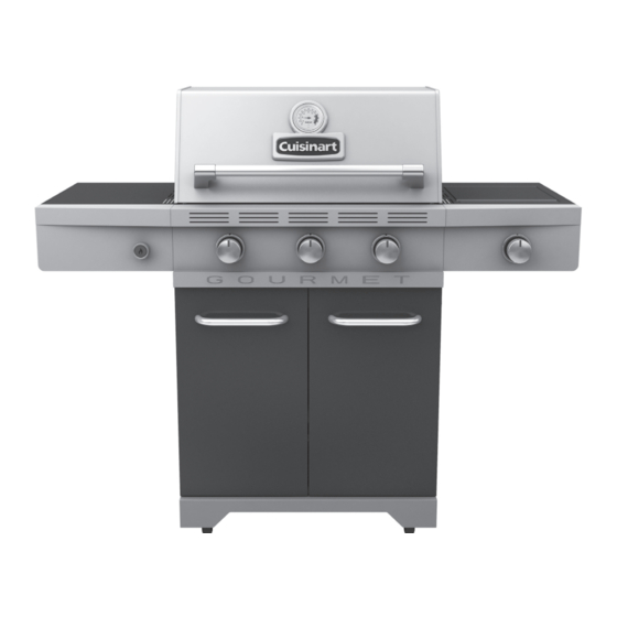
cuisinart
®
REAd ANd SAvE MANUAL foR fUtURE REfERENcE.
Missing or damaged parts should be claimed within 30 days of purchase.
for product inquiries, parts, warranty and troubleshooting support, please call 1-800-309-3452.
LiMitEd 5-YEAR WARRANtY
Gourmet 710
Assemble your grill immediately.
www.cuisinartbbqs.com
ASSEMBLY
MANUAL
85-3108-6 (G53501) Propane
85-3109-4 (G53502) Natural Gas
Manual Revision #: 09152014 AT
Advertisement

Related Manuals for Cuisinart Gourmet 710


Summary of Contents for Cuisinart Gourmet 710
- Page 1 ASSEMBLY MANUAL 85-3108-6 (G53501) Propane cuisinart Gourmet 710 ® 85-3109-4 (G53502) Natural Gas REAd ANd SAvE MANUAL foR fUtURE REfERENcE. Assemble your grill immediately. Missing or damaged parts should be claimed within 30 days of purchase. for product inquiries, parts, warranty and troubleshooting support, please call 1-800-309-3452.
- Page 2 H E A V Y A R T I C L E N E E D S 2 T O L I F T THIS MANUAL MUST REMAIN WITH THE PRODUCT AT ALL TIMES to oRdER non-warranty replacement parts or accessories, or to register your warranty, please visit us on the web at www.cuisinartbbqs.com cAUtioN...
-
Page 3: Hardware Pack
HARDWARE PACK tools Needed for Assembly No. Description Part Number Qty. 1/4-20UNCx38 Screw 20120-13038-250 • #2 Phillips screwdriver (long and short) 1/4-20UNCx16 Screw 20120-13016-250 • ¼” Slotted screwdriver (long and short) NO.10-24UNCx13 Screw 20124-10013-250 • Adjustable wrench ST4.2X10 Tapping Screw 22500-42010-137 φ7 Lock Washer 41400-07000-250... - Page 4 PARTS LIST (PROPANE) FOR 85-3108-6 (G53501) Item No. Qty. Description Part No. Item No. Qty. Description Part No. Top lid G535-2000-01 Side Shelf Table - Right G535-0400-01 Lid Handle G535-0002-01 Side Shelf Fascia - Right G535-0500-01 Lid Handle End Cap G358-0004-01 Side Burner Drip Pan G515-0083-02...
- Page 5 EXPLODED DIAGRAM (PROPANE) FOR 85-3108-6 (G53501) EXtRAS Assembly Safe Use Manual & Care Hardware Tank Manual Pack Screw...
- Page 6 PARTS LIST (NATURAL GAS) FOR 85-3109-4 (G53502) Item No. Qty. Description Part No. Item No. Qty. Description Part No. Top lid G535-2000-01 Side Shelf Table - Right G535-0400-01 Lid Handle G535-0002-01 Side Shelf Fascia - Right G535-0500-01 Lid Handle End Cap G358-0004-01 Side Burner Drip Pan G515-0083-02...
- Page 7 EXPLODED DIAGRAM (NATURAL GAS) FOR 85-3109-4 (G53502) EXtRAS Assembly Safe Use Manual & Care Hardware Manual Pack...
-
Page 8: Assembly Instructions
ASSEMBLY INSTRUCTIONS Separate the 2 different types of wheels: 2 Locking Wheels (ED) and 2 Regular Wheels (EE). Insert the U Pin (#12) into one of the regular Wheels (EE), as shown in image B. Attach the Regular Wheel (EE) to the front of the Bottom Shelf (EC), and use the U Pin (#12) to secure and tighten. - Page 9 ASSEMBLY INSTRUCTIONS c. Assemble the Lower Back Panel (CP) to the Left Cart Side Panel (EA) and Right Cart Side Panel (EB). YoU WiLL NEEd: tiP: The top of the lower back panel (CP) can be identified by the four recesses located on the top of this part.
- Page 10 ASSEMBLY INSTRUCTIONS tHiS StEP REQUiRES 3 PEoPLE. do Not AttEMPt ALoNE. EXtREMELY HEAvY. a. Position the Top Lid and Burner Box Assembly (A and B) onto Cart Assembly (C), as shown. Front view Close up - left outside view b. Assemble Burner Box Assembly (A and B) to the Left and Right Cart Side Panels (EA and EB), as shown.
- Page 11 ASSEMBLY INSTRUCTIONS Attach the Upper Back Panel (CL) to both the Left and Right Cart Side Panels (EA and EB). Only install hardware in the bottom portion of the Upper Back Panel (CL), as shown in figure do Not tiGHtEN ScREWS UNtiL SidE SHELf HAS BEEN iNStALLEd.
- Page 12 ASSEMBLY INSTRUCTIONS a. Open the Lid. Assemble the Left Side Shelf Assembly (DH and DI) to the Cart Assembly by inserting the Side Shelf tabs into holes on the Cart Assembly (figure A). Front, left side view b. Secure using hardware, as shown in figure B, C and D.
- Page 13 ASSEMBLY INSTRUCTIONS a. Remove the Electronic Ignition Battery Cap (CE2) and the plastic nut from the Electronic Ignition Assembly (CE1). Plastic Nut b. Feed the Electronic Ignition Assembly (CE1) through the opening in the Left Side Shelf Fascia (DI) and secure using the nut. Plastic Nut Left side view c.
- Page 14 ASSEMBLY INSTRUCTIONS tiP: The Electrode set for Main Burner (CF), the Electrode wire for Side Burner (DE) can be found fastened together hanging from the left side of the Control Panel on the outside of the burner box (BA) as shown. View under left side shelf d.
- Page 15 ASSEMBLY INSTRUCTIONS a. Open the lid. Assemble the Right Side Shelf Assembly (DA and DB) to the Cart Assembly by inserting the Side Shelf tabs into the holes on the Cart Assembly (figure A). Front, right side view Close up b.
- Page 16 ASSEMBLY INSTRUCTIONS ASSEMBLY INSTRUCTIONS YoU WiLL NEEd: NotE: Beware of sharp edges. View under right side shelf a. Remove the hardware that is pre-assembled to the Side Burner Valve bracket (CC), as shown in figure A. b. Insert the Side Burner Valve stem (CC) through the rear of the Right Side Shelf Fascia (DB).
- Page 17 ASSEMBLY INSTRUCTIONS d. Position the Side Burner (DD) through the opening in the Side Burner Drip Pan (DC). Front, right side view NotE: Make sure that the Side Burner (DD) engages the Side Burner Valve (CC), as shown in figure D. View under right side shelf e.
- Page 18 ASSEMBLY INSTRUCTIONS f. Use the Wing Nut (#10) to assemble the Side Burner (DD) to the Side Burner Drip Pan (DC), as shown in figure F. YoU WiLL NEEd: View under right side shelf g. Attach the end of the Side Burner Electrode Wire (DE) to the underside of the Side Burner (DD), as shown in figure G.
- Page 19 ASSEMBLY INSTRUCTIONS a. Position the Heat Shield (CM) into the two hooks located on the bottom of the Upper Back Panel (CL), as shown in figure A. Back view Close up, back b. Assemble the Heat Shield (CM) to the bottom of the Front Brace (CJ), as shown in figure B.
- Page 20 ASSEMBLY INSTRUCTIONS a. Assemble the Left and Right Tracks (CN and CO) for the Grease Tray (CK), as shown in figure A-C. Front view b. Both the Left and Right Tracks (CN and CO) should be inserted into the two clips located on the Upper Back Panel (CL), as shown in figure B.
- Page 21 ASSEMBLY INSTRUCTIONS Assemble the Door Handle (EH) to the Left and Right Door Assembly (EF and EG) as shown in figure A. YoU WiLL NEEd: a. Assemble the Right Door Assembly (EG), to the Bottom Shelf (EC) by inserting the fixed pin (bottom of door) into the hole provided (figure B).
- Page 22 ASSEMBLY INSTRUCTIONS Place the Flame Tamers (BD) into the Burner Box (BA). a. Place the Cooking Grates (BE) into the Burner Box (BA), as shown. b. Assemble the Warming Rack (BF) by inserting the fixed pins into the warming rack support bars located on the Burner Box (BA), as shown in figure A and B.
- Page 23 Attach the regulator coupling nut to the LP cylinder valve. Be careful not to cross thread. Hand tighten only. d. Perform Leak Test. See page 5 of the Cuisinart Safety and Care Manual. ® AttENtioN: For your families safety,...
- Page 24 NAtURAL GAS ModEL oNLY. a. Attach the Natural Gas Hose (CB) to the Side Burner Valve (CC) as shown. b. Perform Leak Test. See page 6 of the Cuisinart Safety and Care Manual. ® AttENtioN: In order to complete installation of your Natural Gas BBQ a 1/2”...
-
Page 25: Join The Conversation
Gourmet Barbecues customer Service: ® 1-800-309-3452 Join the conversation facebook.com/cuisinartbbqs twitter.com/cuisinartbbqs Cuisinart is a registered ® trademark used under license © 2015 Trileaf Distributions Trifeuil...
Need help?
Do you have a question about the Gourmet 710 and is the answer not in the manual?
Questions and answers