Sign In
Upload
Download
Table of Contents
Contents
Add to my manuals
Delete from my manuals
Share
URL of this page:
HTML Link:
Bookmark this page
Add
Manual will be automatically added to "My Manuals"
Print this page
×
Bookmark added
×
Added to my manuals
Manuals
Brands
WeldCorp Manuals
Welding System
MIG 100
Owner's operating manual
WeldCorp MIG 100 Owner's Operating Manual
Gas/gasless
Hide thumbs
Also See for MIG 100
:
Owner's operating manual
(18 pages)
1
2
Table Of Contents
3
4
5
6
7
8
9
10
11
12
13
14
15
16
17
18
19
20
21
22
23
24
25
26
27
28
29
30
31
32
page
of
32
Go
/
32
Contents
Table of Contents
Troubleshooting
Bookmarks
Table of Contents
Table of Contents
Safety Instructions
Description of Machines
Mig 100
Mig 120
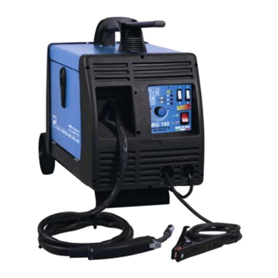
Mig 160
Assembly Instructions
Set up of the Welder (Gas and Gasless)
Operation
Operation-Gas or no Gas Application
Key Points to Feeding the Welding Wire
Feeding the Welding Wire
- F I T T I N G T H E G a S B O T T L E
Welding Basics
Thermal Overload
Welding Information
Wire Extensions (Wire Stick Out)
Starting the Arc
Techniques
Welding Examples
Trouble Shooting Guide
Spare Parts
Mig 100
Mig 120 / 160
Warranty
Warranty Form
Contact Details
Advertisement
Quick Links
1
Mig 100
2
Mig 120
3
Mig 160
4
Set up of the Welder (Gas and Gasless)
5
Operation-Gas or no Gas Application
6
Mig 120 / 160
Download this manual
OWNERS OPERATING MANUAL
CONGRATULATIONS ON YOUR PURCHASE OF A QUALITY WELDCORP WELDER
MANUFACTURED IN ITALY, IT WILL PROVIDE YEARS OF RELIABLE OPERATION.
Table of
Contents
Previous
Page
Next
Page
1
2
3
4
5
Advertisement
Table of Contents
Need help?
Do you have a question about the MIG 100 and is the answer not in the manual?
Ask a question
Questions and answers
Related Manuals for WeldCorp MIG 100
Welding System Weldcorp MIG 100 Owner's Operating Manual
Gasless welder (18 pages)
Welding System Weldcorp Mig 160 Owner's Operating Manual
Electronic inverter dual purpose welder gas/gasless (21 pages)
Welding System WeldCorp MIG 120 Owner's Operating Manual
Gas/gasless (32 pages)
Welding System WeldCorp ARC 140 Owner's Operating Manual
(24 pages)
Welding System WeldCorp INVERTER 80 Owner's Operating Manual
(24 pages)
Welding System WeldCorp MULTI PULSE PRO 240 Owner's Operating Manual
Mig/tig/arc 240 electronic inverter inverter multi pulse pro (23 pages)
Welding System Weldcorp WCPC001 Owner's Operating Manual
Weld and cut arc/tig inverter plasma 30 plasma cutter (18 pages)
Welding System WELDCORP ARC 140 AMP Owner's Operating Manual
(18 pages)
Welding System Weldcorp TIG PRO 170 Owner's Operating Manual
Electronic inverter arc/tig welder (19 pages)
Welding System WeldCorp INVERTER TIG140 Owner's Operating Manual
Electronic inverter arc/tig welder (15 pages)
This manual is also suitable for:
Mig 120
Mig 160
Table of Contents
Save PDF
Print
Rename the bookmark
Delete bookmark?
Delete from my manuals?
Login
Sign In
OR
Sign in with Facebook
Sign in with Google
Upload manual
Upload from disk
Upload from URL


Need help?
Do you have a question about the MIG 100 and is the answer not in the manual?
Questions and answers