
Related Manuals for WeldCorp Mig 160


Summary of Contents for WeldCorp Mig 160
- Page 1 OWNER’S OPERATING MANUAL INVERTER MIG 160 ELECTRONIC INVERTER DUAL PURPOSE WELDER GAS/GASLESS...
-
Page 3: Table Of Contents
• Control panel • Protection device Machine set up (MIG / MAG / MOG) Welding Guide • General welding tips Troubleshooting MIG 160 Welder overview Welding machine technical data Spare parts list 14-15 Wiring Diagram Warranty 17-18 Declaration of conformity... -
Page 4: Safety Instructions
SAFETY INSTRUCTIONS When using power equipment, basic safety precautions should always be followed to reduce the risk of fire, electric shock and personal injury, including the following. If used correctly, welders pose little risk to the operator; however, care should always be taken to ensure safety and proper performance. - Page 5 • DON’T OVERREACH: Keep proper footing and balance at all times. • DRESS PROPERLY: DO NOT wear loose clothing or jewellery. They can be caught in moving parts. Wear protective hair covering to cover long hair, and gloves and non-slip footwear is recommended when working outdoors.
-
Page 6: Inverter Mig Welders
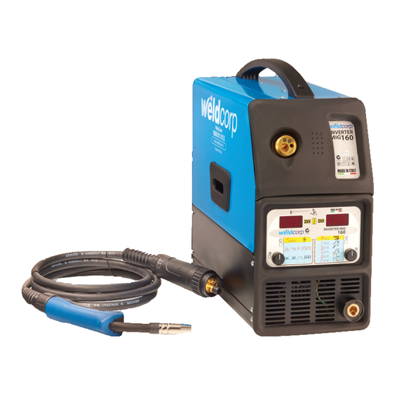
INVERTER MIG 160 DUAL PURPOSE WELDERS The welding machine is manufactured with advanced inverter technology and is suitable for MIG/MAG/MOG welding. It is highly reliable, handy, compact and can be supplied with single-phase voltage from 220V to 240V, 50/60Hz. It allows the MIG welding for copper,... -
Page 7: Welder Information
INSTALLATION (cont.) HANDLE ASSEMBLY Assemble the handle on the welding machine mantle like in Fig. 2. Make sure of the correct tightening of the screws and of the held of handle before lilt the machine. WELDER INFORMATION The machine functions are controlled by the control panel on the front panel. The panel is composed of two displays, “DISP-1”... - Page 8 WELDER INFORMATION (cont.) Through the pressure and rotation of ENC-1 it’s possible to set the following settings shown on DISP-1: After 3 seconds, if the knobs aren’t pushed, or the machine is in stand by mode, the display DISP-1 shows the value set for the wire speed, while display DISP-2 shows the value set for the power.
-
Page 9: Protection Device
WELDER INFORMATION (cont.) Pressing and turning ENC-2, it is possible to set the following functions, shown on the display DISP-2: PROTECTION DEVICE The duty cycle is the fraction or percentage of a ten-minute cycle that a power source may be used without overheating. For example, a welding machine with 150 amp - 30% duty cycle can weld continuously at 150 amps for 3 minutes, and then must cool down during the remaining 7 minutes to prevent overheating, with the ambient temperature of 40”C. -
Page 10: Machine Set Up (Mig / Mag / Mog)
MACHINE SET UP - MIG / MAG / MOG Below are shown guidelines to set up the machine for a MIG/MAG and MOG welding. 1) Turn off the welding machine. 2) Connect the plug of the work clamp to the Negative socket “-” (Figure 1.A.5) and the plug of the cable GAS I NO GAS (Figure 1.A.4) to the Positive socket “+”... -
Page 11: Welding Guide
WELDING GUIDE GENERAL RULE When welding on the lowest output settings, it is necessary to keep the arc as short as possible. This should be achieved by holding the welding torch as close as possible and at an angle of approximately 60 degrees to the work piece. The arc length can be increased when welding on the highest settings, an arc length up to 20mm (0,8in). -
Page 12: Troubleshooting
TROUBLESHOOTING If you are still having difficulty with your welder, do not hesitate to contact our service team on: 1800 011 812 Page 11... -
Page 13: Mig 160 Welder Overview
MIG 160 WELDER Page 12... -
Page 14: Welding Machine Technical Data
WELDING MACHINE TECHNICAL DATA Page 13... -
Page 15: Spare Parts List
SPARE PARTS LIST - INVERTER MIG 160 DUAL PURPOSE Product Code: WCM0005 Page 14... - Page 16 SPARE PARTS LIST - INVERTER MIG 160 DUAL PURPOSE Product Code: WCM0005 Page 15...
-
Page 17: Wiring Diagram
WIRING DIAGRAM Page 16... -
Page 18: Warranty
1YEAR WARRANTY Subject to the warranty conditions below, this Weldcorp product (“the Product”) is warranted by ITW Group, a division of ITW Australia Pty Ltd (“the Company”) to be free from defects in material or workmanship for a period of 12 months from the date of original purchase (“the Warranty Period”). - Page 19 WARRANTY FORM THIS WARRANTY FORM SHOULD BE REAINED BY THE CUSTOMER AT ALL TIMES For your record and to assist in establishing date of purchase (necessary for in warranty service) please keep your purchase docket and this form completed with the following particulars. PURCHASED FROM SUBURB DATE...
-
Page 20: Declaration Of Conformity
Page 19... - Page 21 Manufactured in Italy Cyclone Tools Pty Ltd ABN 89 169 427 061 73C Elizabeth Street Wetherill Park NSW 2164 www.weldcorp.com.au AUS Helpline: 1800 001 812...
Need help?
Do you have a question about the Mig 160 and is the answer not in the manual?
Questions and answers