Table of Contents
Advertisement
w elcoming
allen + roth
®
es una marca registrada de
LF, LLC. Todos los derechos reservados.
ADJUNTE SU RECIBO AQUÍ
Número de serie
Fecha de compra
Preguntas, problemas, piezas faltantes?Antes de regresar al vendedor, llame a nuestro
departamento de servicio al ciente al 1-866-439-9800, de lunes a jueves de 8 a.m. a 6 p.m. (hora del
este) y viernes de 8 a.m. a 5 p.m. (hora del este).
•
sophisticated
•
inspiring
ARTÍCULO #0357652
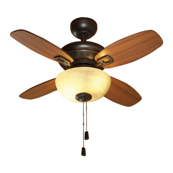
VENTILADOR DE TECHO
LARALYN
MODELO #00882
MODELO UL #LRN32
Lowes.com/allenandroth
19
w elcoming
allen + roth
®
is a registered trademark
of LF, LLC. All Rights Reserved.
ATTACH YOUR RECEIPT HERE
Serial Number
Purchase Date
Questions, problems, missing parts? Before returning to your retailer, call our customer service
department at 1-866-439-9800, 8 a.m. – 6 p.m., EST, Monday - Thursday, 8 a.m. – 5 p.m., EST, Friday.
EB 14200
•
sophisticated
•
inspiring
ITEM #0357652
LARALYN CEILING FAN
MODEL #00882
UL MODEL #LRN32
Español p. 19
Lowes.com/allenandroth
1
Advertisement
Table of Contents

Subscribe to Our Youtube Channel
Related Manuals for Allen + Roth 00882


Summary of Contents for Allen + Roth 00882
- Page 1 • sophisticated • inspiring ARTÍCULO #0357652 ITEM #0357652 allen + roth ® es una marca registrada de allen + roth ® is a registered trademark LF, LLC. Todos los derechos reservados. VENTILADOR DE TECHO LARALYN CEILING FAN of LF, LLC.
-
Page 2: Table Of Contents
TABLE OF CONTENTS SAFETY INFORMATION READ AND SAVE THESE INSTRUCTIONS Safety Information........................3 Please read and understand this entire manual before attempting to assemble, operate or install the product. Package Contents........................4 • When using an existing outlet box, be sure the box is securely attached to the building structure and can support the full weight of the fan, so as to avoid potential serious injury or death. -
Page 3: Package Contents
PACKAGE CONTENTS HARDWARE CONTENTS (shown actual size) Plastic Plug Wire Qty. 1 Connector Fan Pull Chain Light Pull Chain Qty.4 Extension Extension Qty. 1 Qty. 1 (NOT TO SCALE) (NOT TO SCALE) Blade Bracket Screw with Blade Screw Washer Rubber Gasket Qty. -
Page 4: Initial Installation
INITIAL INSTALLATION INITIAL INSTALLATION 1. Determine mounting method to use: 4. Install the mounting bracket (A) to the outlet box (not Outlet box A-Downrod Mount (standard or angled ceiling) included), sliding the mounting bracket (A) over the two B-Closemount (standard ceiling only) outlet box screws (not included). -
Page 5: Closemount-Style Fan Mounting
DOWNROD-STYLE FAN MOUNTING CLOSEMOUNT-STYLE FAN MOUNTING 1. Remove the canopy cover (C) from the bottom of the 3. Loosen preassembled set screws from the yoke on canopy (B). motor housing assembly (H). Slip downrod (E) into yoke, aligning holes on both parts. Insert previously removed pin through holes on yoke and downrod (E), then insert previously removed clip into the pin until it snaps into place. -
Page 6: Wiring
CLOSEMOUNT-STYLE FAN MOUNTING WIRING 4. Align mounting holes on canopy (B) with holes on motor 2. Tape the wire connectors (AA) and wires together. The housing assembly (H) and fasten using three previously wires should be spread apart with the grounded conductor and the equipment-grounding conductor on removed screws. -
Page 7: Warning
FINAL INSTALLATION FINAL INSTALLATION 3. Install the non-slotted screws previously removed (Step 6. Remove the preassembled screws from the switch 3, page 6) to canopy (B) and tighten securely. housing cover on motor housing assembly (H). Outlet box Screw If using fan WITH the light kit, continue to Step 7, If using fan WITHOUT the light kit, proceed to Step 14. - Page 8 FINAL INSTALLATION FINAL INSTALLATION 9. Install bulbs (L) into sockets. 12. Place previously removed rubber washer and hex nut Note: This fan has an energy-saving wattage limiter (Step 10, page 14) onto the pipe and securely tighten. included. If you replace the candelabra-base bulbs with Pass fan pull chain through side hole on bowl cap (M), over 190 watts, the light will automatically turn off.
-
Page 9: Operation Instructions
OPERATION INSTRUCTIONS FINAL INSTALLATION 1. PULL CHAIN: 15. Insert the plastic plug (DD) into the center hole in the (1). The fan pull chain is for motor speed control: High, Medium, Low and Off. Pull the chain once switch housing (I). for each position. -
Page 10: Warranty
EST, Monday - Thursday, 8 a.m. - 5 p.m., EST, Friday. PART DESCRIPTION PART # Blade Bracket 104000-0317UT Blade 108001-603977 Glass Bowl 991300-0546PL Printed in China allen + roth is a registered ® trademark of LF, LLC. All rights reserved. Lowes.com/allenandroth...
Need help?
Do you have a question about the 00882 and is the answer not in the manual?
Questions and answers