Table of Contents
Advertisement
Available languages
Available languages
welc
a
ring
allen + roth
®
is a registered trademark
ITEM #0233061
of LF, LLC. All Rights Reserved.
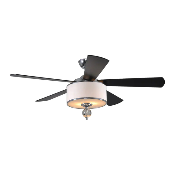
VICTORIA HARBOR CEILING FAN
MODEL #LP8242LCH
Español p. 23
ATTACH YOUR RECEIPT HERE
Serial Number
Purchase Date
Questions, problems, missing parts? Before returning to your retailer, call our customer service
department at 1-888-567-2055, 8 a.m. - 5 p.m., EST, Monday - Friday.
EB13242
Lowes.com/allenandroth
1
Advertisement
Chapters
Table of Contents

Related Manuals for Allen + Roth VICTORIA HARBOR


Summary of Contents for Allen + Roth VICTORIA HARBOR
- Page 1 + roth ® is a registered trademark ITEM #0233061 of LF, LLC. All Rights Reserved. VICTORIA HARBOR CEILING FAN MODEL #LP8242LCH Español p. 23 ATTACH YOUR RECEIPT HERE Serial Number Purchase Date Questions, problems, missing parts? Before returning to your retailer, call our customer service department at 1-888-567-2055, 8 a.m.
-
Page 2: Table Of Contents
TABLE OF CONTENTS Package Contents ......................... Hardware Contents ........................Safety Information ......................... Preparation ........................... Assembly Instructions ........................Wiring Instructions ........................Final Assembly Instructions ......................Operating Instruction ........................Blade Balancing Instructions ......................Care and Maintenance ......................... Troubleshooting ..........................Warranty ............................Replacement Parts List ........................ Lowes.com/allenandroth... -
Page 3: Package Contents
PACKAGE CONTENTS Motor Assembly Glass Hanger Bracket Connection Stud Assembly Downrod Trim Cover Ceiling Canopy Trim Ball Canopy Screw Cover Bulb Motor Coupling Cover Receiver Unit Light Plate Shade Assembly Remote Socket Plate Assembly Blade Lowes.com/allenandroth... -
Page 4: Hardware Contents
HARDWARE CONTENTS (shown actual size) Fiber Washer-Head Washer Wire Screw Connector Qty. 16 Qty. 4 Qty. 16 Balance (not shown to size) Qty. 1 SAFETY INFORMATION Please read and understand this entire manual before attempting to assemble, operate or install the product. -
Page 5: Preparation
SAFETY INFORMATION and can radiate radio frequency energy and, if not installed and used in accordance with the instructions, may cause harmful interference to radio or television reception, which can be determined by turning the equipment off and on, the user is encouraged to try to correct the interference by one or more of the following measures: - Reorient or relocate the receiving antenna. -
Page 6: Assembly Instructions
ASSEMBLY INSTRUCTIONS 1. Remove the hanger ball portion from the downrod (C) by loosening the preassembled set screw in the hanger ball until the ball falls freely down the downrod (C). Remove the preassembled pin from the downrod (C), then remove the hanger ball. - Page 7 ASSEMBLY INSTRUCTIONS 4. Thread the downrod (C) into downrod support of the motor assembly (A). Align the holes in the downrod support of the motor assembly (A) with the holes in the downrod (C) and install the previously removed clevis pin. Secure clevis pin with previously removed hairpin clip.
- Page 8 ASSEMBLY INSTRUCTIONS 6. Reinstall the hanger ball on the downrod (C) by routing the two 54 in. wires from the motor assembly (A) through the hanger ball. Position the pin removed in step 1 through the two holes in the downrod (C) and align the hanger ball so the pin is captured in the groove in the top of the hanger ball.
- Page 9 ASSEMBLY INSTRUCTIONS WARNING To avoid possible electrical shock, be sure electricity is turned off at the main fuse box before hanging. NOTE: If you are not sure if the outlet box is grounded, contact a licensed electrician for advice, as it must be grounded for safe operation.
-
Page 10: Wiring Instructions
WIRING INSTRUCTIONS WARNING To avoid possible electrical shock, be sure electricity is turned off at the main fuse box before wiring this fan. NOTE: If you are not sure if the outlet box is grounded, contact a licensed electrician for advice, as it must be grounded for safe operation. - Page 11 WIRING INSTRUCTIONS 3. Slide the receiver unit (N) into the open end of the hanger bracket (B). 4. Connect green wires from hanger bracket (B) and downrod (C) to bare (ground) wire using wire connector (CC). Connect black wire from receiver unit (N) marked “AC IN L”...
- Page 12 WIRING INSTRUCTIONS 5. After connections have been made, turn leads upward and carefully push leads into the outlet box, with the white and green leads to one side of the box and the black leads toward the other side. Lowes.com/allenandroth...
-
Page 13: Final Assembly Instructions
FINAL ASSEMBLY INSTRUCTIONS 1. Remove one of the two preassembled shoulder screws in the hanger bracket (B). Loosen the second shoulder screw without fully removing it. Rotate ceiling canopy (D) so second shoulder screw moves into the small opening of the keyslot. Tighten shoulder screw. - Page 14 FINAL ASSEMBLY INSTRUCTIONS Lowes.com/allenandroth...
- Page 15 FINAL ASSEMBLY INSTRUCTIONS 7. Install bulbs (M). 8. Remove the preassembled nut from thread stud on socket plate assembly (H). Position glass (I) onto the thread stud of socket plate assembly (H) and secure with nut. Do not overtighten. Twist and secure the connection stud assembly (J) onto the thread stud of socket plate assembly (H).
-
Page 16: Operating Instruction
OPERATING INSTRUCTIONS 1. Restore electrical power to the outlet box by turning the electricity on at the main fuse box. WARNING Do not operate this fan with a variable (Rheostat) wall controller or dimmer switch. Doing so could result in damage to the ceiling fan's remote control unit. - Page 17 OPERATING INSTRUCTIONS 4. The remote (O) includes buttons for high, medium and low fan speeds as well as fan OFF and light ON/OFF. Varying light levels are available by holding down the light ON/OFF button. CAUTION If you are not expecting to use the remote for a long period of time, remove the battery to prevent damage to the remote.
-
Page 18: Blade Balancing Instructions
BLADE BALANCING INSTRUCTIONS If the fan wobbles when in use, turn off the fan and follow the below steps: WARNING onto the blade until it touches the edge of the and cause personal injury. 1. Interchanging positions of adjacent blades (P) can redistribute the weight and result in smoother operation. -
Page 19: Care And Maintenance
CARE AND MAINTENANCE When cleaning, use only a soft brush or lint-free cloth to avoid scratching the finish. WARNING Do not use water when cleaning the ceiling fan. It could damage the motor or the finish and create the possibility of electrical shock. RECOMMENDED: Periodically check that the fan motor unit screws, blade screws, support housing and light kit screws are tight and secure. - Page 20 TROUBLESHOOTING PROBLEM POSSIBLE CAUSE CORRECTIVE ACTION Fan sounds noisy. WARNING Make sure main power is turned off! 5. Motor noise caused by solid state 5. Some fan motors are sensitive variable speed control. to signals from solid-state variable speed controls. Solid-state controls are not recommended, choose an alternative control method.
-
Page 21: Warranty
WARRANTY The manufacturer warrants this fan to be free from defects in workmanship and material present at time of shipment from the factory. The warranty terms from the date of purchase. The motor has a lifetime warranty, and a 2 year warranty for the light kit and all remaining components. This warranty applies only to the original purchaser. -
Page 22: Replacement Parts List
Trim Ball P824210CL Bulb PPE12B40 Receiver Unit RECAN55 Remote TR350AR Blade AP824205BLWA Screw HDWBM8242LCH Washer-Head Screw HDWBM8242LCH Wire Connector HDWWNUTS4 Balance Kit LBALKT Printed in China allen + roth ® is a registered trademark of LF, LLC. All rights reserved. Lowes.com/allenandroth... - Page 23 + roth ® es una marca registrada ARTÍCULO #0233061 de LF, LLC. Todos los derechos reservados. VENTILADOR DE TECHO VICTORIA HARBOR MODELO #LP8242LCH ADJUNTAR SU RECIBO AQUÍ Número de serie Fecha de compra ¿Preguntas, problemas, piezas faltantes? Antes de volver a la tienda, llame a nuestro Departamento de Servicio al Cliente al 1-888-567-2055, 8 a.m.
- Page 24 ÍNDICE Contenido del paquete ........................Aditamentos ........................... Información de seguridad ......................Preparación ........................... Instrucciones de ensamblaje ......................Instrucciones de cableado ......................Instrucciones de ensamblaje finales ....................Instrucciones de funcionamiento ....................Instrucciones para balancear las aspas ..................Cuidado y mantenimiento ......................Solución de problemas ........................
-
Page 25: Contenido Del Paquete
CONTENIDO DEL PAQUETE Ó Ó Vidrio Ensamble del motor Ensamble de la varilla de Abrazadera para colgar conexión varilla Tapa del reborde Escudo del techo Bola de reborde Cubierta para los tornillo de Bombilla la base Unidad receptora Cubierta para el acoplador Control remoto de mano del motor Aspa... -
Page 26: Aditamentos
ADITAMENTOS (Se muestan en tamaño real) Arandelas Tornillos con de fibra Conectores cabeza de de cable arandela Cant. 16 Cant. 4 Cant. 16 Kit de equilibrio (no se muestra en tamaño real) Cant. 1 INFORMACIÓN DE SEGURIDAD Lea y comprenda completamente este manual antes de intentar ensamblar, usar o instalar el producto. - Page 27 INFORMACIÓN DE SEGURIDAD ADVERTENCIA No nstale n use el ent lador s falta al una eza o éstas están dañadas. PRECAUCIÓN Lowes.com/allenandroth...
-
Page 28: Preparación
PREPARACIÓN Antes de comenzar a ensamblar el producto, asegúrese de tener todas las piezas. Compare las piezas con la lista del contenido del paquete y la lista de aditamentos. No intente ensamblar el producto si falta alguna pieza o si éstas están dañadas. Tiempo estimado de ensamblaje: 60 minutos Herramientas necesarias para el ensamblaje (no se incluyen): Destornillador Phillips, destornillador de punta plana de 1/4”, pinzas pelacables y escalera de tijera. -
Page 29: Instrucciones De Ensamblaje
INSTRUCCIONES DE ENSAMBLAJE 1. Retire la parte correspondiente a la bola para colgar del varilla (C) aflojando el tornillo de fijación de la bola hasta que ésta salga libremente de la varilla (C). Retire el pasador preensamblado de la varilla (C) y luego retire la bola para colgar. - Page 30 INSTRUCCIONES DE ENSAMBLAJE 4. Enrosque la varilla (C) en el soporte de la varilla en el ensamble del motor (A). Alinee los orificios en el soporte de la varilla del ensamble del motor (A) con los orificios en la varilla (C) e instale el pasador de horquilla que retiró...
- Page 31 INSTRUCCIONES DE ENSAMBLAJE 6. Vuelva a instalar la bola para colgar en la varilla (C) haciendo pasar los dos conductores de 1,37 m del ensamble del motor (A) a través de la bola para colgar. Coloque el pasador que retiró en el paso 1 a través de los dos orificios de la varilla (C) y alinee la bola para colgar de manera tal que el pasador quede inserto en la ranura de la parte superior de la bola para...
- Page 32 INSTRUCCIONES DE ENSAMBLAJE ADVERTENCIA Para evitar una posible descarga eléctrica, asegúrese de cortar la alimentación eléctrica de la caja de fusibles principal antes de colgar el ventilador. NOTA: Si no está seguro de si la caja de salida tiene conexión a tierra, pida consejo a un electricista certificado, ya que debe tener conexión a tierra para un funcionamiento seguro.
-
Page 33: Instrucciones De Cableado
INSTRUCCIONES DE CABLEADO ADVERTENCIA Para evitar una posible descarga eléctrica, asegúrese de cortar la alimentación eléctrica de la caja de fusibles principal antes de cableado el ventilador. NOTA: Si no está seguro de si la caja de salida tiene conexión a tierra, pida consejo a un electricista certificado, ya que debe tener conexión a tierra para un funcionamiento seguro. - Page 34 INSTRUCCIONES DE CABLEADO 3. Deslice la unidad receptora (N) en el extremo abierto de la abrazadera para colgar (B). 4. Conecte los conductores verdes de la abrazadera para colgar (B) y la varilla (C) al conductor desnudo (a tierra) con el conector de cables (CC).
- Page 35 INSTRUCCIONES DE CABLEADO 5. Una vez realizadas las conexiones, gire los conductores hacia arriba y, con cuidado, colóquelos dentro de la caja de salida; con los Caja de salida conductores blancos y verdes hacia un lado y Blanco homologada los conductores negros hacia el otro. Conductor verde Negro (puesta a tierra)
-
Page 36: Instrucciones De Ensamblaje Finales
INSTRUCCIONES DE ENSAMBLAJE FINALES 1. Retire uno de los dos tornillos de reborde preensamblados en el abrazadera para colgar (B). Afloje el segundo tornillo de reborde sin retirarlo del todo. Gire la base de techo (D) de modo que el segundo tornillo de reborde se desplace a la abertura pequeña del chavetero. - Page 37 INSTRUCCIONES DE ENSAMBLAJE FINALES Lowes.com/allenandroth...
- Page 38 INSTRUCCIONES DE ENSAMBLAJE FINALES 7. Instale la bombilla (M). 8. Retire la tuerca preensamblada de la varilla roscada en el ensamble de la placa del portalámpara (H). Coloque la vidrio (I) en la varilla roscada del ensamble de la placa del portalámpara (H) y fíjela con una tuerca.
-
Page 39: Instrucciones De Funcionamiento
INSTRUCCIONES DE FUNCIONAMIENTO 1. Restablezca la alimentación eléctrica en la caja de salida volviendo a conectar la electricidad de la caja de fusibles principal. ADVERTENCIA No utilice este ventilador con un controlador variable de pared (Rheostat) o un regulador de intensidad. Si lo hiciera podría dañar la unidad del mando a distancia del ventilador de techo. - Page 40 INSTRUCCIONES DE FUNCIONAMIENTO 4. El control remoto (O) incluye botones para velocidades alta, media y baja, además del APAGADO del ventilador y el ENCENDIDO/APAGADO de la iluminación. Podrá acceder a diferentes niveles de iluminación al presionar hacia abajo el botón de ENCENDIDO/APAGADO de la iluminación.
-
Page 41: Instrucciones Para Balancear Las Aspas
INSTRUCCIONES PARA BALANCEAR LAS ASPAS Si el ventilador tambaleo cuando está en uso, apague el ventilador y siga los siguientes pasos: ADVERTENCIA El sujetador de equilibrio siempre se debe empujar firmemente en el aspa hasta que toque el borde de ésta. Si no lo hace, el sujetador puede salir disparado y causar daños personales. -
Page 42: Cuidado Y Mantenimiento
CUIDADO Y MANTENIMIENTO Use sólo una brocha suave o un paño sin pelusas para evitar rayar el acabado al limpiarlas. acabado. ADVERTENCIA No use agua para limpiar el ventilador de techo. Puede dañar el motor o el acabado y crea la posibilidad de una descarga eléctrica. - Page 43 SOLUCIÓN DE PROBLEMAS PROBLEMA CAUSA POSIBLE ACCIÓN CORRECTIVA El ventiladoremite 4. Los conectores al interior de la 4. Compruebe que los conectores mucho ruido. carcasa repiquetean. de cable de la carcasa del interruptor no repiqueteen unos contra otros o contra las paredes interiores de la carcasa del interruptor.
-
Page 44: Garantía
GARANTÍA El fabricante garantiza, de por vida, (con limitaciones) que este ventilador no presenta defectos ni de fabricación ni en los materiales presentes en el momento del transporte desde la fábrica a partir de la fecha de compra. Esta garantía es válida sólo para el comprador original. El fabricante acepta reparar dichos defectos sin cargo o, según nuestro criterio, reemplazar el ventilador de techo por un modelo comparable o superior. -
Page 45: Lista De Piezas De Repuesto
Control remoto de mano Aspa AP824205BLWA Tornillos con cabeza de arandela HDWBM8242LCH Arandelas de fibra HDWBM8242LCH Conectores de cable HDWWNUTS4 Kit de equilibrio LBALKT Impreso en China allen + roth ® es una marca registrada de LF, LLC. Todos los derechos reservados. Lowes.com/allenandroth...
Need help?
Do you have a question about the VICTORIA HARBOR and is the answer not in the manual?
Questions and answers
how to change the light bulb in the Allen Roth Victoria Harbor ****
@Judith A Cook
@Judith A Cook the glass piece itself is screwed in. Spin it until it comes out. Took me forever to figure it out!