Table of Contents
Advertisement
Available languages
Available languages
allen + roth
is a registered trademark
®
of LF, LLC. All Rights Reserved.
ATTACH YOUR RECEIPT HERE
Serial Number
Questions, problems, missing parts? Before returning to your retailer, call our customer service
department at 1-888-567-2055, 8 a.m. - 5 p.m., EST, Monday - Friday.
EB13239
welcoming
•
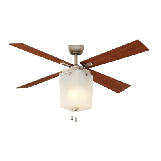
LE MARCHE CEILING FAN
Purchase Date
1
sophisticated
Lowes.com/allenandroth
•
inspiring
ITEM #0199985
MODEL #LP8130LBN
Español p. 21
Advertisement
Chapters
Table of Contents

Related Manuals for Allen + Roth Le Marche


Summary of Contents for Allen + Roth Le Marche
- Page 1 ITEM #0199985 allen + roth is a registered trademark ® of LF, LLC. All Rights Reserved. LE MARCHE CEILING FAN MODEL #LP8130LBN Español p. 21 ATTACH YOUR RECEIPT HERE Serial Number Purchase Date Questions, problems, missing parts? Before returning to your retailer, call our customer service department at 1-888-567-2055, 8 a.m.
-
Page 2: Table Of Contents
TABLE OF CONTENTS Package Contents ......................... Hardware Contents ........................Safety Information ......................... Preparation ........................... Assembly Instructions ........................Wiring Instructions ........................Final Assembly Instructions ......................Operating Instructions ........................Blade Balancing Instructions ......................Care and Maintenance ......................... Troubleshooting ..........................Warranty ............................Replacement Parts List ........................ Lowes.com/allenandroth... -
Page 3: Package Contents
PACKAGE CONTENTS PART DESCRIPTION QUANTITY PART DESCRIPTION QUANTITY Motor Assembly Blade Holder Arm Hanger Bracket Blade Downrod Ceiling Canopy Canopy Screw Cover Motor Coupling Cover Housing Assembly Light Plate Assembly Lampshade Bulb Lowes.com/allenandroth... -
Page 4: Hardware Contents
HARDWARE CONTENTS (shown actual size) Fiber Washer-Head Washer Wire Screw Screw Connector Qty. 13 Qty. 9 Fan Chain Light Kit Chain Qty. 4 Qty. 13 Balance Coupler Coupler (not shown Qty. 1 Qty. 1 to size) Qty. 1 SAFETY INFORMATION Please read and understand this entire manual before attempting to assemble, operate or install the product. -
Page 5: Preparation
SAFETY INFORMATION WARNING • Do not install or use fan if any part is damaged or missing. • To reduce the risk of fire, electrical shock, or personal injury, wire connectors provided with this fan are designed to accept only one 12-gauge house wire and two lead wires from the fan. If your house wire is larger than 12-gauge or there is more than one house wire to connect to the two fan lead wires, consult an electrician for the proper size wire connectors to use. -
Page 6: Assembly Instructions
ASSEMBLY INSTRUCTIONS 1. Remove the hanger ball portion from the downrod (C) by loosening the preassembled set screw in the hanger ball until the ball falls freely down the downrod (C). Remove the preassembled pin from the downrod (C), then remove the hanger ball. - Page 7 ASSEMBLY INSTRUCTIONS 4. Thread the downrod (C) into downrod support of the motor assembly (A). Align the holes in the downrod support of the motor assembly (A) with the holes in the downrod (C) and install the previously removed clevis pin. Secure clevis pin with previously removed hairpin clip.
- Page 8 ASSEMBLY INSTRUCTIONS 7. Cut off excess lead wire approximately 6 to 9 in. above top of the top of the downrod (C). Strip insulation off 1/2 in. from the end of each lead wire. WARNING To avoid possible electrical shock, be sure electricity is turned off at the main fuse box before hanging.
- Page 9 ASSEMBLY INSTRUCTIONS 9. Carefully lift the assembly and seat hanger ball of the downrod (C) on the hanger bracket (B). Be sure the groove in the ball is lined up with tab on the hanger bracket (B). WARNING Failure to seat tab in groove could cause damage to electrical wires and possible shock or fire hazard.
-
Page 10: Wiring Instructions
WIRING INSTRUCTIONS WARNING To avoid possible electrical shock, be sure electricity is turned off at the main fuse box before wiring. NOTE: If you are not sure if the outlet box is grounded, contact a licensed electrician for advice, as it must be grounded for safe operation. -
Page 11: Final Assembly Instructions
FINAL ASSEMBLY INSTRUCTIONS 1. Remove one of the four preassemble screws inside the motor assembly (A). Slightly loose the remaining three screws. Assemble the housing assembly (G) to the motor assembly (A) using the three key slots in the housing assembly (G). - Page 12 FINAL ASSEMBLY INSTRUCTIONS 4. Remove one of the two preassembled shoulder screws in the hanger bracket (B). Loosen the second shoulder screw without fully removing it. Rotate ceiling canopy (D) so second shoulder screw moves into the small opening of the keyslot. Tighten shoulder screw.
- Page 13 FINAL ASSEMBLY INSTRUCTIONS 7. Remove one of the four preassemble screws inside the housing assembly (G). Slightly loosen the remaining three screws. Assemble the light plate assembly (H) to the hosing assembly (G) using the three key slots. Replace the fourth screw and secure all four screws.
-
Page 14: Operating Instructions
OPERATING INSTRUCTIONS 1. Restore electrical power to the outlet box by turning the electricity on at the main fuse box. 2. Install the fan chain coupler (EE) and light kit chain coupler (FF). Hardware Used Fan Chain Coupler Light Kit Chain Coupler 3. - Page 15 OPERATING INSTRUCTIONS 4. Check the operation of the light by gently pulling on the light kit chain coupler (FF). Light Kit Pull Chain Operating Sequence Pull Pull 5. If airflow is desired in the opposite direction, turn the fan off and wait for the blades to stop turning.
-
Page 16: Blade Balancing Instructions
BLADE BALANCING INSTRUCTIONS If the fan wobbles when in use, turn off the fan and follow the below steps: WARNING The balancing clip must always be firmly pushed onto the blade until it touches the edge of the blade. Failure to do so could allow clip to fly off and cause personal injury. -
Page 17: Care And Maintenance
CARE AND MAINTENANCE • When cleaning, use only a soft brush or lint-free cloth to avoid scratching the finish. • Abrasive cleaning agents are not required and should be avoided to prevent damage to finish. WARNING • Do not use water when cleaning the ceiling fan. It could damage the motor or the finish and create the possibility of electrical shock. - Page 18 TROUBLESHOOTING PROBLEM POSSIBLE CAUSE CORRECTIVE ACTION Fan sounds noisy. 5. Screws holding blades to blade 5. Tighten screws securely. holders are loose. 1. Set screw in downrod support is loose. 1. Tighten set screws securely in Fan wobbles downrod support. excessively.
-
Page 19: Warranty
WARRANTY The manufacturer warrants this fan to be free from defects in workmanship and material present at time of shipment from the factory. The warranty terms from the date of purchase. The motor has a lifetime warranty, and a 2 year warranty for the light kit and all remaining components. This warranty applies only to the original purchaser. -
Page 20: Replacement Parts List
HDWBH8130CH Washer-Head Screw HDWBM8130CH Fiber Washers HDWBM8130CH Wire Connector HDWWNUTS4 Fan Chain Coupler ALP000005LBN Light Kit Chain Coupler ALP000006LBN Balancing Kit LBALKT Printed in China allen + roth ® is a registered trademark of LF, LLC. All rights reserved. Lowes.com/allenandroth... - Page 21 ARTÍCULO #0199985 allen + roth es una marca registrada ® de LF, LLC. Todos los derechos reservados. VENTILADOR DE TECHO LE MARCHE MODELO #LP8130LBN ADJUNTAR SU RECIBO AQUÍ Número de serie Fecha de compra ¿Preguntas, problemas, piezas faltantes? Antes de volver a la tienda, llame a nuestro Departamento de Servicio al Cliente al 1-888-567-2055, 8 a.m.
- Page 22 ÍNDICE Contenido del paquete ........................Aditamentos ........................... Información de seguridad ......................Preparación ........................... Instrucciones de ensamblaje ......................Instrucciones de cableado ......................Instrucciones de ensamblaje finales ....................Instrucciones de funcionamiento ....................Instrucciones para balancear las aspas ..................Cuidado y mantenimiento ......................Solución de problemas ........................
-
Page 23: Contenido Del Paquete
CONTENIDO DEL PAQUETE PIEZA DESCRIPCIÓN CANTIDAD PIEZA DESCRIPCIÓN CANTIDAD Ensamble del motor Ensamble de la placa de Abrazadera para colgar iluminación Pantalla Varilla Escudo del techo Bombilla Brazo de soporte del aspa Cubierta para los tornillo de la base Aspa Cubierta para el acoplador del motor Ensamble de carcasa... -
Page 24: Aditamentos
ADITAMENTOS (Se muestra en tamaño real) Arandelas Tornillos con de fibra Conectores cabeza de Tornillos de cable arandela Qty. 13 Cant. 9 Acoplador de Acoplador de Cant. 4 Cant. 13 Kit de equilibrio la cadena la cadena (no se muestra del ventilador del kit de en tamaño real) -
Page 25: Preparación
INFORMACIÓN DE SEGURIDAD ADVERTENCIA • No instale ni use el ventilador si falta alguna pieza o si éstas están dañadas. • Para reducir el riesgo de incendios, descargas eléctricas o lesiones personales, los conectores de cable incluidos con este ventilador están diseñados para soportar sólo un cable interior de calibre 12 y dos cables conductores del ventilador. -
Page 26: Instrucciones De Ensamblaje
INSTRUCCIONES DE ENSAMBLAJE 1. Retire la parte correspondiente a la bola para colgar de la varilla (C) aflojando el tornillo de fijación de la bola hasta que ésta salga libremente de la varilla (C). Retire el pasador preensamblado de la varilla (C) y luego retire la bola para colgar. - Page 27 INSTRUCCIONES DE ENSAMBLAJE 4. Enrosque la varilla (C) en el soporte de la varilla en el ensamble del motor (A). Alinee los orificios en el soporte de la varilla del ensamble del motor (A) con los orificios en la varilla (C) e instale el pasador de horquilla que retiró...
- Page 28 INSTRUCCIONES DE ENSAMBLAJE 7. Corte el excedente del cable conductor aproximadamente en unos 15,24 cm a 22,86 cm por sobre la parte superior de la varilla (C). Pele 1,27 cm del aislamiento del extremo de cada cable conductor. ADVERTENCIA Para evitar una posible descarga eléctrica, asegúrese de cortar la alimentación eléctrica de la caja de fusibles principal antes de colgar el ventilador.
- Page 29 INSTRUCCIONES DE ENSAMBLAJE 9. Con cuidado levante el ensamble y coloque la bola para colgar de la varilla (C) en la abrazadera para colgar (B). Asegúrese de que la ranura de la bola esté alineada con la lengüeta de la abrazadera para colgar (B). ADVERTENCIA Si no coloca la lengüeta en la ranura, podrían dañarse los cables eléctricos y...
-
Page 30: Instrucciones De Cableado
INSTRUCCIONES DE CABLEADO ADVERTENCIA Para evitar una posible descarga eléctrica, asegúrese de cortar la alimentación eléctrica de la caja de fusibles principal antes de cableado el ventilador. NOTA: Si no está seguro de si la caja de salida tiene conexión a tierra, pida consejo a un electricista certificado, ya que debe tener conexión a tierra para un funcionamiento seguro. -
Page 31: Instrucciones De Ensamblaje Finales
INSTRUCCIONES DE ENSAMBLAJE FINALES 1. Extraiga uno de los cuatro tornillos preensamblados de la unidad del motor (A). Afloje levemente los tros tres tornillos. Instale la ensamble de la carcasa (G) en el ensamble del motor (A) utilizando las tres ranuras principales en el ensamble de la carcasa (G). - Page 32 INSTRUCCIONES DE ENSAMBLAJE FINALES 4. Retire uno de los dos tornillos de reborde preensamblados en el abrazadera para colgar (B). Afloje el segundo tornillo de reborde sin retirarlo del todo. Gire la base de techo (D) de modo que el segundo tornillo de reborde se desplace a la abertura pequeña del chavetero.
- Page 33 INSTRUCCIONES DE ENSAMBLAJE FINALES 7. Retire uno de los cuatro tornillos preassembledel ensamble ensamble de carcasa(G). Afloje ligeramente los tres tornillos restantes. Coloque el ensamble de la placa de iluminación (H) en el ensamble de la carcasa (G) usando los tres chaveteros. Vuelva a colocar el cuarto tornillo y apriete todos los tornillos.
- Page 34 INSTRUCCIONES DE FUNCIONAMIENTO 1. Restablezca la alimentación eléctrica en la caja de salida volviendo a conectar la electricidad de la caja de fusibles principal. 2. Instale el acoplador de la cadena del ventilador (EE) y el acoplador de la cadena del kit de iluminación (FF).
-
Page 35: Instrucciones De Funcionamiento
INSTRUCCIONES DE FUNCIONAMIENTO 4. Verifique el funcionamiento de la luz jalando suavemente del acoplados de la cadena del kit de iluminación (FF). Secuencia de funcionamiento de la cadenilla del kit de iluminación 1.ª tirada Encendido Apagado 1.ª tirada 5. Si desea que el flujo de aire corra en la dirección opuesta, apague el ventilador y espere hasta que las aspas dejen de girar. -
Page 36: Instrucciones Para Balancear Las Aspas
INSTRUCCIONES PARA BALANCEAR LAS ASPAS Si el ventilador tambaleo cuando está en uso, apague el ventilador y siga los siguientes pasos: ADVERTENCIA El sujetador de equilibrio siempre se debe empujar firmemente en el aspa hasta que toque el borde de ésta. Si no lo hace, el sujetador puede salir disparado y causar daños personales. -
Page 37: Cuidado Y Mantenimiento
CUIDADO Y MANTENIMIENTO • Use sólo una brocha suave o un paño sin pelusas para evitar rayar el acabado al limpiarlas. • Los agentes limpiadores abrasivos son innecesarios y deben evitarse para no dañar el acabado. ADVERTENCIA • No use agua para limpiar el ventilador de techo. Puede dañar el motor o el acabado y crea la posibilidad de una descarga eléctrica. - Page 38 SOLUCIÓN DE PROBLEMAS PROBLEMA CAUSA POSIBLE ACCIÓN CORRECTIVA El ventilador emite 4. Los conectores al interior de la 4. Compruebe que los conectores mucho ruido. carcasa repiquetean. de cable de la carcasa del interruptor no repiqueteen unos contra otros o contra las paredes interiores de la carcasa del interruptor.
-
Page 39: Garantía
SOLUCIÓN DE PROBLEMAS PROBLEMA CAUSA POSIBLE ACCIÓN CORRECTIVA No hay La varilla es demasiado corta. Si es posible, piense en utilizar una varilla más larga suficiente (no se incluye). movimiento de aire. GARANTÍA El fabricante garantiza, de por vida, (con limitaciones) que este ventilador no presenta defectos ni de fabricación ni en los materiales presentes en el momento del transporte desde la fábrica a partir de la fecha de compra. -
Page 40: Lista De Piezas De Repuesto
Conectores de cable ALP000005LBN Acoplador de la cadena del ventilador Acoplador de la cadena del kit de ALP000006LBN iluminación Kit de equilibrio LBALKT Impreso en China allen + roth® es una marca registrada de LF, LLC. Todos los derechos reservados. Lowes.com/allenandroth...
Need help?
Do you have a question about the Le Marche and is the answer not in the manual?
Questions and answers