Table of Contents
Advertisement
Quick Links
–
For full installation, configuration, and operation details, refer to the
NOTE
VSP 618 user manual, which is available at www.rgblink.com.
This guide provides quick start instructions for an experienced installer
to set up and operate the VSP 618.
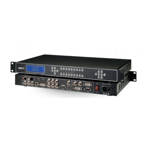
Installation and cabling features
Connections
1
Mini Switches
2
10 11
LAN RJ-45 port
3
13
USB control port
4
RS232 control port
6
5
HDMI Input Connectors
~
7
9
SDI Female BNC connector
TX Card Power Connector
12
TX Card DVI Input Connector
14
Step 1-Mounting
Turn off or disconnect all equipment power sources.
Step 2-HDMI Input
Used to connect the video sources from HDD
Media player, DVD Player, Computer. (HDMI
Inputs are optional modules, for VSP 618 to
support HDMI inputs model are VSP 618C, VSP
618BC or VSP 618BCD.)
Step 3-SDI Input
Used to connect the video sources from HDD Media
Player, HD Camera. ( SDI Inputs are optional
modules, for VSP 618 with SDI inputs model are
VSP 618B, VSP 618BC or VSP 618BCD.)
Step 4-SDI Loop out
SDI loop out connector is used to connect another
VSP 618B or other SDI-based equipment.
Step 5- Composite Input
Used to input composite signal
(PAL, NTSC, SECAM compatible).
Step 6-S-Video input
Used to input S-Video signal
(PAL, NTSC, SECAM compatible).
Address:S603-604 Weiye Building Torch Hi-Tech Industrial Development Zone Xiamen,Fujian Province, P.R.C
Tel: 00865925771197
Email: rgblinkcs@gmail.com
VIEWSIZE THE WORLD
~
Composite Female BNC connectors
15
17
S-Video (DIN 4) Input connector
18
DVI (DVI-I) Input Connector
19
~
Component Female BNC Connector
20
22
DSUB 15-pin VGA Input Connector
23
24
HDMI Ouput Connector
DVI Output Connector
25
Fax:00865925771202
http://www.rgblink.com
26 DSUB 15-pin VGA Output Connector
27
Power Switch Button
28 Power Cord Connector IEC-3
Step 7-DVI input
Input the signal from computer,
DVI signal generator and so on.
Step 8-Component input
Used to input signal from Players
like DVD; Input signal as R/Pr G/Y B/Pb
from left.
Step 9-VGA input
Input from computer or VGA source.
Step 10-HDMI output
Used to connect HDMI-based monitor or
LED Display Control system which has
HDMI interface.
Step 11-DVI output
Connect to the monitor or LED control
system which has DVI interface.
Step 12-VGA output
Connect to the monitor, projector and so on.
VSP 618 Quick Start
Rev 1.0
Page 1 of 3
Advertisement
Table of Contents

Related Manuals for RGBlink vsp 618


Summary of Contents for RGBlink vsp 618
- Page 1 – For full installation, configuration, and operation details, refer to the NOTE VSP 618 user manual, which is available at www.rgblink.com. This guide provides quick start instructions for an experienced installer to set up and operate the VSP 618. Installation and cabling features...
- Page 2 RJ11 Connector Step18- Power Output resolution should be the same or large than the Plug in power cord which has IEC connector, VSP 618 monitor or display system resolution. support AC power from 85 to 260 VAC,50-60Hz, which More resolutions can be accessed from PC.
- Page 3 Step 5-Save Subtitle switch VSP 618 support 2 user saving mode. Push SAVE button Click “Subtitle on/off”button to insert and SVAE1, SVAE2 buttons will light on, push any one of the subtitle,and click the them to save the setting. After that user can push each of “transparent background”if user likes.
Need help?
Do you have a question about the vsp 618 and is the answer not in the manual?
Questions and answers