
Related Manuals for Uniden GDVR 4A Series


Summary of Contents for Uniden GDVR 4A Series
-
Page 1: Security System
GdVr 4a/8a series security system For more exciting new products please visit our website: australia: www.uniden.com.au OWNER’S Manual... -
Page 2: Important Safeguards
iMPortant saFeGuards WarninG risK oF electrical sHocK do not oPen WARNINg: TO ReDUCe The RISK OF eLeCTRIC ShOCK, DO NOT RemOVe COVeR. NO USeR SeRVICeABLe PARTS INSIDe. ReFeR SeRVICINg TO QUALIFIeD SeRVICe PeRSONNeL. The exclamation point within an equilateral triangle is intended to alert the user to the presence of important operating and maintenance (servicing) instructions in the literature accompanying the appliance. -
Page 3: General Precautions
General Precautions All warnings and instructions in this manual should be followed. Remove the plug from the outlet before cleaning. Do not use liquid aerosol detergents. Use a water-dampened cloth for cleaning. Do not use this product in humid or wet places. Keep enough space around the product for ventilation. - Page 4 instructions read and Follow instructions - All the safety and operating instructions should be read before the product is set up and used. Follow all operating instructions. retain instructions - These safety and operating instructions should be retained for future reference. Heed Warnings - Comply with all warnings on the product and in the operating instructions.
- Page 5 built-in installation such as a bookcase or rack unless proper ventilation is provided and the product manufacturer’s instructions have been followed. 10. Water and Moisture - Do not use this product near water - for example, near a bath tub, wash bowl, kitchen sink or laundry tub, in a wet basement, near a swimming pool, etc.
- Page 6 • If the product does not operate normally by following the operating instructions. Adjust only those controls that are covered by the operating instructions. Improper adjustment of other controls may result in damage and will often require extensive work by a qualified technician to restore the product to its nor mal operation.
-
Page 7: Table Of Contents
contents introduction ....................9 WHat’s in tHe BoX? ..................10 GettinG to KnoW Your dVr ..............11 GettinG to KnoW Your caMeras ............12 installation ....................13 setuP......................15 SySTem LOgIN .................15 ReQUIReD SeTTINgS ..............15 DeFAULT OPeRATION SeTTINgS ...........16 HoW do i - ..................17 SeARCh FOR FILeS ................17 SeT UP ALARmS AND ALARm NOTIFICATION? ......17 PLAy BACK ReCORDeD FILeS ............17 FIND AND VIeW ShAPShOTS ............17... - Page 8 searcH icon ..................62 TIme SeARCh TAB ................62 eVeNT SeARCh TAB ................63 FILe mANAgemeNT TAB ..............64 ImAge TAB ..................65 BacKuP icon ..................66 inForMation icon ................67 SySTem SCReeN ................68 eVeNT LIST SCReeN ................68 LOg LIST SCReeN ................69 NeTWORK SCReeN ................69 ONLINe USeRS LIST SCReeN ............70 exIT SCReeN ..................70 disK ManaGeMent icon ..............
-
Page 9: Introduction
introduction oVerVieW The guardian DVR AhD (gDVR AhD) system operates with an embedded LINUx operating system for increased stability. It also uses standard h. 264 video compression and g. 711 audio compression technology which provide high quality, detailed playback and analysis. TCP/IP network technology provides the gDVR AhD system with strong network data transmission and remote control operation. -
Page 10: What's In The Box
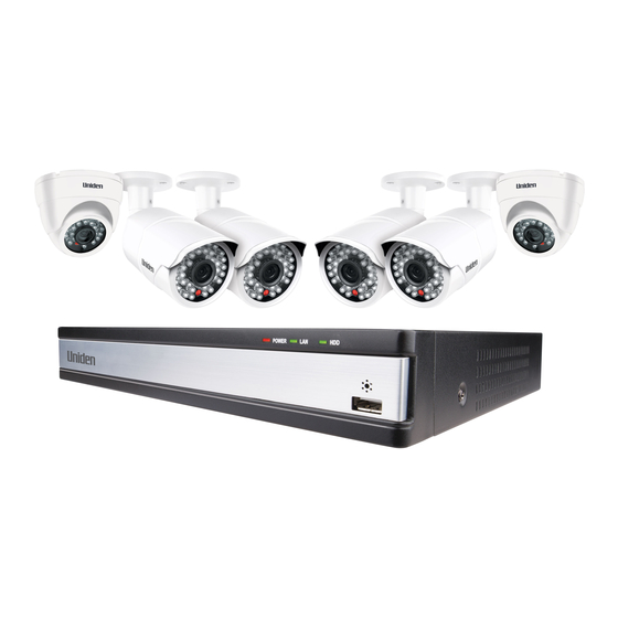
What’s in the Box Model 4-ch dVr 8-ch dVr outdoor camera indoor camera With 1TB hDD With 1TB hDD gDVR 4A40 gDVR 4A22 gDVR 8A42 each DVR comes with: each Camera comes with: 1. Power Splitter Cable 7. Video Power cable 8. -
Page 11: Getting To Know Your Dvr
Getting to Know Your dVr Front Power Port Back rJ45 (ethernet cable) (external display) rs485 alarM in/out Video in audio out HdMi audio in (If using PTZ cameras) (external (cameras) speaker) dc12V (AC Adaptor) Video out usB Port (external display) (mouse/ external hD) -
Page 12: Getting To Know Your Cameras
Getting to Know Your cameras indoor camera Infra-red LeDs Camera Lens Light Sensor BNC Video Connector (green) Power Connector (Red) outdoor camera Infra-red LeDs Camera Lens Light Sensor Power Connector (Red) BNC Video Connector (green) -
Page 13: Installation
installation Follow the steps below to connect the DVR and the camera(s). modem/Router external Display Camera ethernet Cable hDmI Cable Video Power Cable AC Adaptor (Power Outlet) Power Splitter Cable AC Adaptor (Power Outlet) mouse 1. Connect the camera to the BNC and Power connectors on the Video Power cable. - Page 14 6. Connect the ethernet cable to the RJ45 port on the DVR and to your modem/router (for remote viewing). 7. Connect the Power Splitter cable to the camera’s AC adaptor, which connects to a power outlet. 8. Plug the DVR’s AC Adaptor jack into the DC12V port (on the DVR) and the other end to a power outlet.
-
Page 15: Setup
setuP Live video displays when you power up the system. however, until you log in, you can only view live video; you cannot access any other system operations. (For the initial set up, a series of Wizard screens pop up. Change the default parameters, if necessary, if not, click Next, till you reach the screen that displays Finish. -
Page 16: Default Operation Settings
Uniden strongly recommends that, once you have logged into the system, you create a password for the Admin user. From Main Menu/Users/User Management, select the Password field. See page 54 for a detailed description on how to set up a password. -
Page 17: How Do I
HoW do i - search for Files There are three basic methods for searching files – i) search for files within a certain time frame, ii) search a time frame for triggered files, and iii) search for events through the Information screen. The first two methods use the search screen (Main Menu/search). -
Page 18: Set Up Email Notification And Alert
Set Up Email Notification and Alert Main Menu/setup/Network, Email tab Configure Alarms Main Menu/setup/alarms. Select type of alarm (Sensor, motion, Video Loss, or Other Alarm). create a recording schedule Main Menu/setup/schedule. you can set up recordings by a specific calendar schedule, or according to sensor type. -
Page 19: Guardianlive App
View live and recorded video remotely using an iOS or Android device and Uniden’s guardianLive App. From the Apple App Store or google Play, download the Uniden guardianLive app. Open the app. Tap create account. The create account screen displays. - Page 20 liVe screen Live Screen is the main screen in the guardianLive app. Back Camera Name Quad View Date &Time display Pause microphone hD/SD Refresh Remote Playback Alarm Snapshot Record Audio...
- Page 21 Pause Tap on a camera view and tap the Pause icon to stop live view. Play Tap on a camera view and tap the Play icon to start the streaming of live view. audio Tap to turn on audio (not available on all models). alert Tap to open the Alarm setting screen and save configuration, so that you can be alerted when...
- Page 22 reMote PlaYBacK screen On the app, in the live view, tap the Playback icon to get the Remote Playback screen displayed. Tap the date displayed on the top right corner of the screen to get the select Date pop-up box. Tap to scroll through the dates and select the dates that you want to play the recorded video.
- Page 23 snaPsHot screen On the Device List screen, tap on the menu icon (top left corner) to reveal menu options, About, Recordings, Snapshots and Logout. Tap the option, snapshots, to view the images that have been taken using the app. Please note, these images are NOT stored on the hard disk. loGout Tap to logout of the app.
-
Page 24: Basic Operation
Basic oPeration Live video displays when you power up the system. however, until you log in, you can only view live video; you cannot access any other system operations. sYsteM loGin Right-click on the screen. The system menu displays. Select any option. The Login screen displays. The default values are admin (user name) with no password. - Page 25 Icons MeanInG Recording Type - indicated by box color • green - manual or triggered recording • yellow - motion detection recording • Blue - Schedule recording • Red - Alarm recording motion Detected. This icon displays when the camera for that view detects motion.
-
Page 26: System Menu
sYsteM Menu In Live view, right-click on any screen to bring up the system menu. Right-click again to close the system menu. The system menu manages the gDVR receiver and cameras. Use it to configure and manage your video, cameras, and recordings. many of these menus are shortcuts to commonly-used actions from the Main Menu screen. - Page 27 Menu IteM DescrIptIon e-Zoom When the screen is in single camera mode and e-Zoom is selected, that camera zooms in for a close up view. The full view displays in the lower left corner. Right-click to return to the quad view. Audio Choose which channel you want to hear audio from and adjust the audio volume.
-
Page 28: Main Menu Overview
Main Menu oVerVieW The main menu screen displays icons that represent various system operations. Click on an icon to configure, operate, and maintain the gDVR system. Appendix A: Menu Structure shows how the menu, screens, and tabs for screens are organized in the system. From the system menu, select Main Menu (see page 26). -
Page 29: Setup Icon
MaIn Menu DescrIptIon Icon Disk Select the Disk Management icon to view information about management the system hard disk and any connected USB drives. See page 71 for icon and screen details. Logoff This selection logs you off of the gDVR system. See page 72 for icon and screen details. -
Page 30: System Tab
System Tab FIelD DescrIptIon Client or system name. Click the field and a popup system Type keyboard displays. enter a name if desired. system Number Used when managing multiple DVR systems. Click the field and a popup number keypad displays. enter a number, if desired. - Page 31 Date & Time Tab In this interface, set the date format, time format, time zone; you can also adjust the system time manually. Note: the default time zone of the system is GMT+10:00. Select sync Time with NTP server to correct time. Network server time can be set.
- Page 32 DST Tab Set the start and end time of daylight saving time by week or date. FIelD DescrIptIon Turn DST on or off. This does not set DST; it turns the Enable system’s ability to keep track of DST on or off. Time Offset Select 1 or 2 hour offset.
-
Page 33: Live Screen
FIelD DescrIptIon Set DST ending date. (Always the first Sunday in April, Until offset 1 hour) If mode = Week, set DST by month, number of week, day of week, and hours to be offset (i.e., April/the 1st/Sunday/1 hour offset) If mode = Date, set DST by date according to popup calendar. - Page 34 FIelD DescrIptIon camera Name enter a camera name for each channel using the popup keyboard. Click to display the colour settings: colour • Channel number • Brightness • hue • Saturation • Contrast Live Tab Name the camera and set up how the image displays (colour, contrast, etc). Select a camera to rename.
- Page 35 The Live screen displays again. Main Monitor Tab This screen lets you determine the order in which the camera’s live view displays on the screen’s sections. you can also set how long the video pauses on each image before moving to another image (5 to 60 seconds in 5 second intervals).
- Page 36 From the Video Blind tab, select setting for the channel you want to mask. Video for that channel displays. Press and hold the left mouse button and drag it across the area you want to block. A white rectangle covers the area you indicated. Release the mouse.
-
Page 37: Record Screen
Record screen The Record screen configures how the files will be recorded. It has 5 tabs: enable • Record Bitrate • Stamp • Recycle Record • Snap • Enable Tab Use this tab to determine if the selected camera will record video or audio, or both. - Page 38 Record Bitrate Tab This tab allows you to set the characteristics of a recorded file. you can set a channel to record at a higher quality or at lower frames per second. The resolution, frames per second, and maximum bitrate determine how large a recorded file will be.
- Page 39 Stamp Tab Use this tab to turn on (or off) a time stamp on your recorded video and to position the time stamp on the screen. FIelD DescrIptIon camera Name Check to display the channel name. Time stamp Check to display the time on this channel. Position move the date/time block to a different area of the screen Select setting on the stamp tab.
- Page 40 Recycle Record Tab The Recycle Record tab allows the system to automatically overwrite the oldest recorded files and continue recording when the hard disk is full. If the box is not checked (not enabled), the system stops recording and displays an information message.
-
Page 41: Schedule Screen
Schedule screen The schedule screen lets you set up recording schedules. It has 3 tabs: Schedule • motion • Sensor • Schedule Tab This tab sets up a basic schedule for recording. (Default = No recording blocks selected) Select a channel whose recording schedule you want to set up. Select the edit icon ( ) to set 1-hour blocks, depending on when you WANT that channel to record. - Page 42 If you want to use that same configuration on another channel, select that channel in the dropdown box for apply settings To. Then, select copy. The configuration is now saved on the second desired channel. If you want to apply the settings from one channel to ALL channels, select all in the dropdown box for apply settings To.
-
Page 43: Alarm Screen
Alarm screen The gDVR system allows you to set parameters for various types of system alarms. The alarm screen is comprised of 4 icons: Sensor. enable and name the type of sensor you choose for a specific • channel. motion. establish parameters for motion detection as well as a motion •... - Page 44 FIelD DescrIptIon Enable Check this to allow sensor operation on a specific channel. Type Normally Closed or Normally Open Name Name the alarm. alarm Handling tab This tab lets you set what triggers alarms and how long those alarms remain active.
-
Page 45: Alarm Tab
To Record • To PTZ • alarm tab FIelD DescrIptIon A buzzer sounds when an alarm is triggered if this Buzzer selection is enabled. show Full A big screen popup alarm displays when an alarm is screen triggered. To alarm Out This tab directs alarms to optional alarms (not included) added to the system. - Page 46 to record tab Select which cameras record when an alarm is triggered. to PtZ Only applies if PTZ camera is installed (not included). Sets what type of action to take (Preset/Cruise/Track/None). • Sets which point the PTZ camera will rotate to, if preset selected. •...
- Page 47 Motion Screen The motion screen has 2 tabs: motion and Schedule. Motion tab When a camera detects a motion, the system sounds a motion detection alarm and takes action according to presets from this screen. The Trigger and area fields lead to other screens to set parameters. FIelD DescrIptIon enable this function on a channel to detect motion.
- Page 48 Set all areas to be Clear the set detection areas detection area Drag the mouse to test whether the sensitivity Save the settings value and the detection area are appropriate or not exit schedule tab Use this tab to set a time frames for the alarms to be active. This tab operates in the same way as the Sensor tab.
- Page 49 Select Trigger for the camera you want to set. The Trigger screen for that channel displays. See page 44 for a detailed description of the trigger screen. Other Alarm Icon FIelD DescrIptIon alarm Type Select one of the following from the drop-down menu: • hard Disk Full • Network Address Conflict • Disconnection...
-
Page 50: Network Screen
Network screen Network Configuration includes five tabs: Network • Sub-Stream • email • WiFi Setup • DDNS • Network Tab do not change these presets. this is for information purposes only. FIelD DescrIptIon HTTP Port Default = 80. server Port Default = 5000. - Page 51 FIelD DescrIptIon alternate DNs Address provided by your network provider. server PPPOE enable this to automatically establish a PPPOe network connection with the DVR. ISP (Internet Service Provider) User Name Password enter the set password. Test Click Test and it will check that the IP address and PPPOe information are valid.
- Page 52 FIelD DescrIptIon Max. Bitrate Select a bitrate from the dropdown box (32kbps ~ 768 kbps). (Default = 64) check the box on the bottom row to set all cameras’ parameters to the same thing at the same time. Email Tab This tab helps you set up how you receive email notifications.
-
Page 53: Users Icon
Selecting this icon brings up the User Management screen. This screen allows you to add and delete users and to change the passwords of existing users. The admin user does not have a password. Uniden strongly recommends that you add a password to the admin user account. -
Page 54: General Tab
General tab FIelD DescrIptIon User Name Provide a user name. enter user’s password to the system Password confirm Reenter user’s password Password User Type Normal or Advanced Binding Pc Links the PC and mAC address. Mac address Computer’s unique hardware number. enter the mAC Pc Mac address address to restrict access to the DVR to only that PC when... -
Page 55: Deleting A User
• Remote Login • System Setup • File management • Shut Down • Disk management • Live View (per camera) • manual Record (per camera) • Playback (per camera) • Backup (per camera) • PTZ Control (per camera) • Remote Live View (per camera) NOTE: If a computer's physical address is 0, the GDVR system does not bind to a specific computer and the user can use any computer to log into the client to use the DVR. -
Page 56: Ptz Icon
enter the fields and select OK. A confirmation screen displays. PtZ icon The Point/Tilt/Zoom icon configures an optional PTZ camera. Tabs in this icon help you set movement patterns. These patterns are Presets (move the camera from point A to point B), Cruise (move the camera through multiple points) or Track. -
Page 57: Advanced Tab
FIelD DescrIptIon Baud Rate PTZ device baud rate. Options are: 1200 2400 4800 9600 19200 34800 57600 115200 230400 460800 921600 Protocol PTZ device standard communication protocols. Options are: PeLCOP PeLCOD LILIN mINKINg NeON STAR VIDO DSCP VISCA SAmSUNg Rm110 N-control simulative Allows the camera to use cruise patterns whether the... - Page 58 FIelD DescrIptIon Preset Click on setting to display the Preset - channel x screen. Click on cruise to display the cruise - channel x screen. cruise Track Click on setting to display the Tracking screen on the full screen for the selected channel. In the Preset column, select setting for the channel you want to work with.
- Page 59 Select a number from the drop down Number list (No.) to assign to the Preset. Click save and the preset points are setting successfully. you can set a maximum of 128 preset points. cruise - channel X screen Select setting under the Cruise column for a specific channel and the cruise - channel X screen displays.
- Page 60 Select the add Preset Point button. A popup field displays. Add preset point Delete the preset point modify the selected preset Controls PTZ recording Start point tracks. Recording Start Wiper Control execute the recorded tracks. Track Control external IR devices hide function Adjust PRZ direction...
-
Page 61: Advanced Icon
Note: Each channel can record only one track, and auto-save after recording is completed. When you call the track, you can directly select the channel to start track. (2) (3) (1) Playback control (2) Channel audio switch (Not available on all models) (3) Function hidden key (4) Operate playback Playback control details as follow:... -
Page 62: Search Icon
Export/Import Parameters If you have to return your DVR to factory settings, all your current settings will be lost. Copy your current system configuration to a USB drive to reload after your DVR has been reset. When you import system parameters from the USB drive, power off your device, insert the USB drive in a USB slot in the BACK of the unit, and then turn the DVR back on. -
Page 63: Event Search Tab
Icons on the playback bar allow you to control the video. event search tab This tab helps you find specific types of events for predetermined dates/ channels. Select a date to search as well as indicate what channels you want to include in the search. -
Page 64: File Management Tab
File Management tab Use this tab to play back recorded files and then keep or delete them. FIelD DescrIptIon search Click to display recorded files according to channel number. Check the box of a file you do not want it accidently Lock deleted (check mark appears in box) and then select Lock. -
Page 65: Image Tab
image tab The Image tab lets you set specific date/time parameters and then display the image from that date/time setting. Direction arrows let you move forward or backward through the saved video. Double-click the image to play back the video from the time when the image was captured. FIelD DescrIptIon search... -
Page 66: Backup Icon
BacKuP icon Back up recorded files to a removeable USB storage device. Insert USB device into USB slot on the back of the unit. DO NOT use the USB slot on the front of the unit; that slot is an alternative USB slot for the mouse only. -
Page 67: Information Icon
Select start. The files transfer to the USB device. inForMation icon Select this icon to find information about your system. The Information screen comprises 6 icons: System • event • • Network • Online Users • exit •... -
Page 68: System Screen
QR codes for iOS and Android systems as well as a Device ID. Scan these codes to download the mobile client and your device’s mobile phone port number when you are setting up the Uniden guardianLive app (see page 19). -
Page 69: Log List Screen
log list screen Select the Log icon and the Log List screen displays. enter start/end times and select what types of operations to search for. Select search and the system displays all events that fit those criteria. network screen Select this icon to display the Network screen. This screen displays existing network parameters for the system. -
Page 70: Online Users List Screen
online users list screen Select this icon to display information on any users currently connected to the DVR system. exit screen Select this icon to return to the Main Menu screen. -
Page 71: Disk Management Icon
disK ManaGeMent icon Select this icon to view files on your hard drive and on a connected USB drive (if applicable). Select the Disk management icon from the Main Menu screen. The Disk Management screen displays. Buttons DescrIptIon Refresh Recheck identifiable disks (hard drive, USB drive, etc.) Browse Displays file names and other information for the... -
Page 72: Log Off Icon
Select cancel to return to the Disk Management screen. loG oFF icon The Logoff icon lets you log out of the system. This does not shut down the system but only logs you (as a user) out of the system. When you select the Logoff icon, a confirmation screen displays. -
Page 73: Remote Access
View live and recorded video remotely using an iOS or android device and Uniden’s guardianLive App. From the Apple App Store, google Play, or the Amazon App store, download the Uniden guardianLive app. Open the app. Tap create account. The create account screen displays. -
Page 74: Firmware Updates
FirMWare uPdates From time to time, Uniden may update its products' firmware to improve features, fix bugs, or otherwise improve the product. Uniden recommends checking for firmware updates every 6 months. Check for firmware updates if you have service issues; your firmware may be out of date. -
Page 75: Troubleshooting
trouBlesHootinG after turning on, the DVr cannot switch on normally. Possible reasons: The power supply is not correct. • Switch power cable is not in good connection. • Switch power is damaged. • The program upgrading is wrong. • The hard disk is damaged or something is wrong with the hard disk cables. •... - Page 76 There is no video input signal or the signal is too weak. • The hardware of the DVR is damaged. • real-time image problems such as serious distortion of the image color or the brightness, etc. Possible reasons: The DVR does not match with the impedance of the monitor. •...
- Page 77 enabled. Click Record icon under Setup to find out. • The corresponding channel is not connected with video (no camera • attached). When the image appear blue screen the playback will be intermittent the time display is wrong. Possible reasons: The time setting is wrong.
- Page 78 The data volume exceeds the backup storage capacity and it will cause • burning errors The backup device is not compatible. • The backup device is damaged. • alarm is not working. Possible reasons: The setting of the alarm is not correct. •...
-
Page 79: Appendix A: Menu Structure
aPPendiX a: Menu structure Click on Main Menu to view Right-click on the screen to view the Main Menu operations. System menus. SETUP Operation * Italic text indicates tabs on screen. RECORD (page xx) SCHEDULE (page xx) ALARM (page xx) NETWORK (page xx) BASIC (page xx) LIVE (page xx) -
Page 80: Appendix B: Hard Disk Capacity Calculation
aPPendiX B: Hard disK aPPendiX B: Hard disK caPacitY calculation make sure the hard disk is installed and successfully formatted when install the DVR for the first time. 1. The capacity of the hard disk itself There is no capacity limit of single hard disk for DVR. you can choose 10g or more. -
Page 81: Specifications
sPeciFication system GDVr 4axx series GDVr 8axx series Pentaplex View, Record, Playback backup, Remote monitoring # Channels Video In 4 BNC 8 BNC Video Out 1 BNC hDmI VgA Out Audio In Audio Out USB Ports 1 Front, 2 Back Alarm In Alarm Out Video Input... - Page 82 1 hDD (SATA), 1 TB included max Capacity Up to 4 TB Backup media USB Flash and hDD Backup File Format connectiVitY Connection Uniden Cloud-based P2P server Supported OS Windows Remote SW PC and mac email Notification With Snapshot SmartPhone,...
- Page 83 system GDVr 4axx series GDVr 8axx series Network Interface RJ-45, 10/100 Base Tx camera specs Image Sensor 1/4” CmOS, 1 megapixel Video Format NTSC/PAL effective Pixels h: 1280 V: 800 Resolution 720P Lens/Type 3.6mm, Fixed max Aperture F2.0 Image 60° 60°...
-
Page 84: Warranty
GdVr 4a/8a series important: Satisfactory evidence of the original purchase is required for warranty service. Please refer to our Uniden website for any details or warranty durations offered in addition to those contained below. Warrantor: The warrantor is Uniden Australia Pty Limited ABN 58 001 865 498 (“Uniden Aust”). - Page 85 Product, together with satisfactory evidence of your original purchase (such as a legible copy of the sales docket) to Uniden. Please refer to the Uniden website for address details. you should contact Uniden regarding any compensation that may be payable for your expenses incurred in making a warranty claim.
- Page 86 © 2015 Uniden Australia Pty Limited. Version 1.0...
Need help?
Do you have a question about the GDVR 4A Series and is the answer not in the manual?
Questions and answers