Table of Contents
Advertisement
Advertisement
Table of Contents

Related Manuals for Conlan CT2000


Summary of Contents for Conlan CT2000
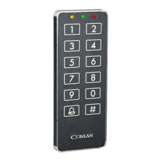
- Page 1 Keypad CT2000 Art. No.: 460001, 460005 (black) Art. No.: 460007, 460014 (white) Installation Manual CT2000_installation_ENGmay15 Conlan ApS • Speditorvej 2A • DK-9000 Aalborg • Tel: +45 72 40 60 03 • Fax: +45 96 32 00 22 www.conlan.eu • info@conlan.eu...
-
Page 2: Table Of Contents
Table of contents Introduction page 3 Programming page 5 2.1 Minimum programming page 5 2.2 Master Code (100) page 7 2.3 Service Code (101) page 7 2.4 ID number (102) page 7 2.5 Output choice (103) page 8 2.6 Blocking time (104) page 10 2.7 LED’s (105) page 11... -
Page 3: Introduction
1. Introduction CT2000 is a advanced keypad manufactured in Denmark. It can be used as stand alone keypad and as a part of a larger system. The keypad has the following features: • Easy to use. • Waterproof. • No mechanical switches - durable. • Precautions against code guessing: • The keypad blocks after 4 invalid codes for a period of up to 255 seonds. • 100 different user codes. • 1 Master Code and 1 Service Code. • All codes can be programmed with 1 to 8 digits. - Page 4 2. Programming Programming of the keypad is done by changing the value of one or more of the 118 different positions. Each of the positions numbered 00 to 102 can contain a code con- sisting of 1 to 8 digits. The rest of the positions controls how the keypad works. Notice:The keypad is different from other keypads on the market. It has no mechanical keys, but is operated just by touching the keys. Pay special attention to the yellow LED. The LED flashes every time the keypad has registered that you have touched a key.
-
Page 5: Programming
13 Programming positions to program the Master Code. Switching output function and/or time CT2000’s open collector output is factory set to provide a 0V DC from it on the po- sitions 110 - 122 programmed time (e.g. in 5 seconds). The open collector outputs functions is programmed in position 103 and is factory set to the value 1, which cor- responds to the above 0V DC whenever you enter the correct code on the keypad. - Page 6 Positions: Position: Controls: 00 - 99 User codes (1 - 8 digits) Master Code (1 - 8 digits) Service Code (1 - 8 digits (factory default 12347890)) ID number Output selection (slave, timer function, reversed timer function). Blocking time in case of code guessing (0 - 255 seconds) LED’s functions and indications.
-
Page 7: Master Code (100)
2.2 Master Code (100) The Master Code is a limited version of the Service Code. It is only authorized to change the values on positions 00 - 99. That means change user codes. The code can be used by the person that is taking care of the daily operation of the system. The Master Code has position 100, but it is empty when the keypad leaves the factory. -
Page 8: Output Choice (103)
2.5 Output choice (103) The value on this position decides how the keypad reacts when typing a user code. Value: Function: (Not used) Output active timer time Inverted output (Not used) Rolling code, 4 digits Rolling kode, 4 digits, inverted output Rolling code, 6 digits Rolling code, 6 digits, inverted output (Not used) - Page 9 Function 4 Rolling code, 4 digits. Function 4, select a option where the keypad accepts a 4 digit code without subsequent use of the < # >. The code is ap- proved, so even though it is in the middle in a longer entry se- quence. Is the correct code example in 1234 and entered the 347123487, approves the code.
-
Page 10: Blocking Time (104)
Function 9 Ask for output status. Function 9 will by entering a code followed by < # > show sta- tus at the output of a number of seconds, after which indication is turned off. The number of seconds can be set from 1 - 30 from position 122. During the status display, it is possible to change the status by typing the <... -
Page 11: Led's (105)
2. LED’s (106) It is possible to control how the 3 LED’s on the top of the keypad should react in your specific installation. Standby refers to which LED that will illuminate when the keypad is in standby mode and ready to be keyed on (yellow LED is the default value). Aktiveret refers to which LED that will illuminate when the keypad is activated when typing on it (green LED flashes when typing a correct user code). -
Page 12: Output Time For Codes (110 - 122)
2.9 Reset By connecting the supply voltage, key in the Service Code (within 10 seconds), followed by < # >, < 250 > and < # >, returns the CT2000 back to factory default as described in section 2 page 4. -
Page 13: Positions
(for approx. 2 seconds) and connect it again to put the keypad into programming mode. +12/42 VDC CT2000 Key in the Service Code, followed by a Key in the touch on the < # > key. All 3 LED’s will... -
Page 14: Changing Positions
(for approx. 2 seconds) and connect it again to put the keypad into programming mode. +12/42 VDC CT2000 Key in the Service Code, followed by a Key in the touch on the < # > key. All 3 LED’s will... -
Page 15: Delete Positions
Disconnect the supply voltage to the keypad (for approx. 2 seconds) and connect it again to put the keypad into programming mode. +12/42 VDC CT2000 Key in the Service Code, followed by a Tast touch on the < # > key. All 3 LED’s will... -
Page 16: Mechanical Mounting
3. Mechanical mounting CT2000 must be mounted on a proper surface. By means of the included drill gauge, the holes for the four screws and the hole for the mounting cable are marked. If the surface is not completely proper, avoid twist or bending the keypad while mounting! Figure 3 shows the mounting, as side view. -
Page 17: Electrical Connection
4. Electrical connection The keypad CT2000 has 4 meters of 8/12 core cable mounted. The following shows how the keypad is to be connected CT2000 keypad 2 pcs. Ø4 mm. for 2,9 mm. screws 2 pcs. Ø4 mm. for 2,9 mm. screws... - Page 18 Brown Pink External control of red LED L. green External control of green LED The yellow core is the open collector, which gives a 0 VDC! CT2000 can be connected to 9 - 27 VDC. For connection to an electric lock - use figure 5. Black White Green Diode...
- Page 19 For connection to an electric lock that uses more than 500 mA - use figure 6. Black White Green Relay Yellow +12 VDC 0 VDC Figure 6: Connection to an electric lock by means of a relay. For connection to a relay - use figure 7. Black White Green +12 VDC Relay Yellow Figure 6: Connection to a relay for general purposes.
- Page 20 The CT2000 can be connected to a assembly box (CVT3). Please consult the manual for CVT3 for further information (Art. No.: 460089 - see figure 8). Normally closed - NC Normally open - NO Common - C Relay - 0V DC Sabotage Sabotage Bus B (RS485) Bus B (RS485) Bus A (RS485)
-
Page 21: Rs485 Communication
5. RS485 Communication The whole 2000 system, inclusive CT2000 us the RS485 communication between the various units. RS485 If the various units in the 2000 system each have their 12V DC power supply (230V AC connected to different phases), there may be a larger voltage difference between the devices, and RS485 circuits can be destroyed. To prevent this, it is nessesary to make sure that the devices have the same potential. -
Page 22: Wired Method
5.2 Wired method When the devices are connected physically, it must be like pearls on string (see draw- ing below). Box 485-T PCI2000/ LogBox3 Box 485-T Prox Star connections must under no circumstances be used. If this is the case with the 2000 system, the T connection are used, the T assembly must be as short as possible. - Page 23 RS485 installation principle From installation Assembly Assembly Forward installation So short cable to CT2000 as possible RS485 forward RS485 backward Supply voltage Note how the RS485 bus in seperate pair of back and forth to the various units in the 2000 system. The power supply can freely be placed as it fits in the installation.
-
Page 24: Technical Specifications
CT2000 with SKAFOR 3 (tamper switch) • 1 Keypad with cable. • 1 Frontlabel • 1 diode • 4 screws (Ø2,9x25mm). • 1 screw (Ø4,0x30mm). • 5 Plugs ( Ø5x25mm). • 1 spring for tamper switch. CT2000 without SKAFOR 3 • 1 Keypad with cable. • 1 Frontlabel • 1 diode • 4 screws (Ø2,9x25mm). • 4 Plugs ( Ø5x25mm). Note: CT2000 must be supplied with a 12 VDC regulated supply voltage (8 - 15 VDC), max 200 mV ripple. -
Page 25: Installation Of Pc Interface
7. Installation of PC Interface 7.1 PCI2000 PCI2000 is a communication interface between a computer and one or more of the following products: • CT2000 keypad and PR2000 proximity reader. • Box 485-T and Box 485-4 PCI2000 can be used to program the 2000 system, and to scan the installation of con- nected devices. - Page 26 Conlan eXPress User window...
- Page 27 Setting window Can be activated/deactivated by: #, #, #, %...
- Page 28 Output times for timer function/inverted timer function (hh:mm:ss) Value Time Value Time Value Time Value Time 0:00 3:15:00 19:15:00 35:15:00 0:01 3:30:00 19:30:00 35:30:00 0:02 3:45:00 19:45:00 35:45:00 0:03 4:00:00 20:00:00 36:00:00 0:04 4:15:00 20:15:00 36:15:00 0:05 4:30:00 20:30:00 36:30:00 0:06 4:45:00 20:45:00...
Need help?
Do you have a question about the CT2000 and is the answer not in the manual?
Questions and answers