Table of Contents
Advertisement
Quick Links
Advertisement
Table of Contents

Related Manuals for Teltonika RUT9 Series


Summary of Contents for Teltonika RUT9 Series
- Page 1 USER MANUAL RUT955 LTERouter...
-
Page 2: Legal Notice
Copyright © 2015 TELTONIKA Ltd. All rights reserved. Reproduction, transfer, distribution or storage of part or all of the contents in this document in any form without the prior written permission of TELTONIKA Ltd is prohibited. The manufacturer reserves the right to modify the product and manual for the purpose of technical improvement without prior notice. -
Page 3: Table Of Contents
Table of Contents Legal notice ................................2 Attention ................................. 2 SAFETY INFORMATION ............................8 Device connection ............................... 9 Introduction ..............................10 Specifications ............................... 10 Ethernet ..............................10 Wi-Fi ................................. 10 Hardware ..............................10 Electrical, Mechanical & Environmental ....................10 Applications ............................. 11 Setting up your router .......................... - Page 4 6.7.4 Realtime Wireless ..........................37 6.7.5 Realtime Connections ........................38 Mobile Traffic ............................39 Speed Test ..............................39 6.10 Events Log ............................40 6.10.1 All Events ............................40 6.10.2 System Events ..........................41 6.10.3 Network Events ..........................42 6.10.4 Events Reporting ..........................43 6.10.5 Reporting Configuration ........................
- Page 5 Services ................................ 79 VRRP ................................. 79 8.1.1 VRRP LAN Configuration Settings ....................79 8.1.2 Check Internet connection ....................... 79 TR-069 ..............................80 8.2.1 TR-069 Parameters Configuration ....................80 Web filter ..............................81 8.3.1 Site blocking ............................. 81 8.3.2 Proxy based URL content blocker ....................81 NTP ................................
- Page 6 8.10.4 Auto Reply Configuration ......................118 8.10.5 SMS Forwarding ..........................119 8.10.6 SMPP .............................. 122 8.11 GPS ..............................123 8.11.1 GPS ..............................123 8.11.2 GPS Settings ........................... 123 8.12 CLI ............................... 124 8.13 Network Shares ..........................124 8.13.1 Mounted File Systems ........................124 8.13.2 Samba ............................
- Page 7 9.3.4 Diagnostics ............................. 155 9.3.5 MAC Clone ............................. 155 9.3.6 Overview ............................156 9.3.7 Monitoring ............................. 157 User scripts ............................157 Safe mode .............................. 158 Firmware ..............................158 9.6.1 Firmware ............................158 9.6.2 FOTA ............................... 159 Restore point ............................160 9.7.1 Restore point create ........................
-
Page 8: Safety Information
SAFETY INFORMATION In this document you will be introduced on how to use a router safely. We suggest you to adhere to the following recommendations in order to avoid personal injuries and or property damage. You have to be familiar with the safety requirements before using the device! To avoid burning and voltage caused traumas, of the personnel working with the device, please follow these safety requirements. -
Page 9: Device Connection
Device connection... -
Page 10: Introduction
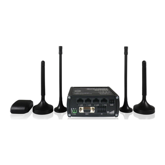
1 Introduction Thank you for purchasing a RUT955 LTE router! RUT955 is part of the RUT9xx series of compact mobile routers with high speed wireless and Ethernet connections. This router is ideal for people who‘d like to share their internet on the go, as it is not restricted by a cumbersome cable connection. -
Page 11: Applications
2.5 Applications 3 Setting up your router 3.1 Installation After you unpack the box, follow the steps, documented below, in order to properly connect the device. For better Wi-Fi performance, put the device in clearly visible spot, as obstacles such as walls and door hinder the signal. 1. -
Page 12: Front Panel And Back Panel
3.1.1 Front Panel and Back Panel 1,2,3 LAN Ethernet ports LTEauxiliary antenna connector WAN Ethernet port GPS antenna connector 5,6,7 LAN LEDs LTE main antenna connector WAN LED USB connector RS485 connector WiFi antenna conectors Power socket Reset button RS232 connector Inputs and outputs connector Power LED Connection LED... -
Page 13: Logging In
3.2 Logging in After you’re complete with the setting up as described in the section above, you are ready to start logging into your router and start configuring it. This example shows how to connect on Windows 7. On windows Vista: click Start -> Control Panel ->... - Page 14 5. Select Internet Protocol Version 4 (TCP/IPv4) and then click 6. By default the router is going to have DHCP enabled, which Properties means that if you select “Obtain an IP address automatically” and “Obtain DNS server address automatically”, the router should lease you an IP and you should be ready to login.
- Page 15 Right click on the Wireless network icon and select Connect / Disconnect. A list should pop up with all available wireless networks. Select “Teltonika” and click connect.Then we launch our favorite browser and enter the routers IP into the address field: Press enter.
-
Page 16: Operation Modes
4 Operation Modes The RUT9xx series router supports various operation modes. It can be connected to the internet (WAN) via mobile, standard Ethernet cable or via a wireless network. If you connect to the internet via an Ethernet cable orWi-Fi, you may also backup your connection with mobile for added stability. -
Page 17: Powering The Device From Higher Voltage
If you want to use high voltage power supplies it is recommended to also use additional safety equipment to suppress voltage peaks from power supply. One of the options is to use “Teltonika” PR1000 overvoltage protection device conforming ISO 7637-2. -
Page 18: Status
6 Status The status section contains various information, like current IP addresses of various network interfaces; the state of the routers memory; firmware version; DHCP leases; associated wireless stations; graphs indicating load, traffic, etc.; and much more. 6.1 Overview Overview section contains various summary information. -
Page 19: System Information
Teltonika Indicates how router will be seen by other devices on the network. Can be changed in System -> Administration. 3. Router Model Teltonika RUT9xx Routers model. 4. Firmware RUT9XX_T_00.00.372 Shows the version of the firmware that is currently loaded in the router. -
Page 20: Network Information
Memory explanation: Field Name Sample Value Explanation 1. Free 94532 kB / 126452 kB The amount of memory that is completely free. Should this rapidly (74%) decrease or get close to 0, it would indicate that the router is running out of memory, which could cause crashes and unexpected reboots. - Page 21 Signal -65dBm Received Signal Strength Indicator (RSSI). Signal's strength measured in strength Cell ID FD90B ID of operator cell that device is currently connected to RSRP -88dBm Indicates the Reference Signal Received Power RSRQ -7dBm Indicates the Reference Signal Received Quality SINR -21.4dBm Indicates the Signalto Interference Noise Ratio...
- Page 22 Netmask* 255.255.255.0 Specifies a mask used to define how large the WAN network is Gateway* 192.168.99.254 Indicates the default gateway, an address where traffic destined for the internet is routed to. DNS* 8.8.8.8 Domain name server(s). Connected* 1h 45m 27s How long the connection has been successfully maintained.
- Page 23 3. Lan name Lan instance name 4. MAC address D4:85:64:65:2B:D4 The MAC (Media Access Control) address of the network interface on which the lease will be used. MAC is specified as a series of hexadecimal octets separated by colons 5. Lease time 10h 11m 13s Remaining lease time for addresses handed out to clients remaining...
- Page 24 connecting to the router. Will show 0% if no devices are trying to connect or are currently maintaining a connection. 8. Bit rate 43.3 MBit/s The physical maximum possible throughput that the routers radio can handle. Keep in mind that this value is cumulative - The bitrate will be shared between the router and other possible devices that connectto the local AP.
- Page 25 Additional note: MBit/s indicates the bits not bytes. To get the throughput in bytes divide the bit value by 8, for e.g. 54MBits/s would be 6.75MB/s (Mega Bytes per second). 6.3.1.5 Associated Stations Outputs a list of all devices and their MAC addresses that are maintain a connection with your router right now. This can either be the information of the Access Point that the router is connecting to in STAmode or a list of all devices that are connecting to the router in AP mode: Field Name...
- Page 26 6.3.1.7 OpenVPN Server Displays openVPN connection server side information. Field Name Sample Value Explanation 1. Status Enabled OpenVPN status 2. Type Server A type of OpenVPN instance that has been created 3. IP 172.16.1.1 Remote virtual network's IP address 4. Mask 255.255.255.255 Remote virtual network's subnet mask 5.
- Page 27 6.3.1.9 VRRP VRRP (Virtual Router Redundancy Protocol) for LAN Field Name Sample Value Explanation 1. Status Enabled VRRP status 2. Virtual IP 192.168.1.253 Virtual IP address(es) for LAN’s VRRP (Virtual Router Redundancy Protocol ) cluster 3. Priority Router with highest priority value on the same VRRP (Virtual Router Redundancy Protocol) cluster will act as a master, range [1 - 255] 4.
- Page 28 6.3.1.10 Topology Network scanner allowing you to quickly retrieve information about network devices.
- Page 29 6.3.1.11 Access Displays information aboutlocal and remote active connections status. Field Name Sample Value Explanation 1. Type SSH;HTTP;HTTPS Type of connection protocol 2. Status Disabled/Enabled Connection status 3. Port 22; 80; 443 Connection port used 4. Active 0(0.00B);1(9.26 KB); Count of active connections and amount of data transmitted in KB Connections 6(558.12 KB) **-Exclusive to other Modes with Slave.
- Page 30 6.3.1.11.1 Last Connections Displays information aboutlocal and remote last 3 connections status Field Name Sample Value Explanation 1. Type SSH;HTTP;HTTPS Type of connection protocol 2. Date 2015-05-11, 10:36:59 Date and time of connection 3. IP 192.168.1.167 IP address from which the connection was made 4.
-
Page 31: Device Information
6.4 Device information The page displays factory information that was written into the device during manufacturing process. Field Name Sample Value Explanation Serial number 02345678 Serial number of the device Product code RUT955101010 Product code of the device Batch number 0222 Batch number used during device’s manufacturing process Hardware revision... -
Page 32: Services
6.5 Services The page displays usage of the available services. 6.6 Routes The page displays ARP table active IP routes of the device. 6.6.1 ARP Shows the routers active ARP table. An ARP table contains recently cached MAC addresses of every immediate device that was communicating with the router. -
Page 33: Active Ip-Routes
6.6.2 Active IP-Routes Shows the routers routing table. The routing table indicates where a TCP/IP packet, with a specific IP address, should be directed to. Field Name Sample Value Explanation 1. Network Interface to be used to transmit TCP/IP packets through 2. -
Page 34: Realtime Graphs
6.7 Realtime Graphs Real-time graphs show how various statistical data changes over time. 6.7.1 Mobile Signal Strenght Displays mobile signal strength variation in time (measured in dBm) Field Name Sample Value Explanation 1. Connection type 3G (WCDMA) Type of mobile connection used 2. -
Page 35: Realtime Load
6.7.2 Realtime Load This tri-graph illustrates average CPU load values in real time. The graph consists out of three color coded graphs, each one corresponding to the average CPU load over 1 (red), 5 (orange) and 15 (yellow) most recent minutes. Field Name Sample Value Explanation... -
Page 36: Traffic
6.7.3 Traffic This tri-graph illustrates average system load over the course of ~3 minutes; each new measurement is taken every 3 seconds. The graph consists out of three color coded graphs, each one corresponding to the average system load over 1 (red), 5 (orange) and 15 (yellow) most recent minutes. Although not graphed, the page also displays peak loads over 1, 5 and 15 minutes. -
Page 37: Realtime Wireless
6.7.4 Realtime Wireless Displaysthe wireless radio signal, signal noise and theoretical maximum channel permeability. Average and peak signal levels are displayed. -
Page 38: Realtime Connections
6.7.5 Realtime Connections Displays currently active network connections. With the information on network, protocol, source and destination addresses, transfer speed. -
Page 39: Mobile Traffic
6.8 Mobile Traffic Displays mobile connection data sent and received in KB of this day, week, month. 6.9 Speed Test Speed test is a tool for measuring your internet connection upload and download speeds. You can select servers for manual testing, or use auto test. -
Page 40: Events Log
6.10 Events Log Event log displays such actions as: login, reboot, firmware flashing and reset. 6.10.1 All Events Displays all router events, their type and time of occurrence. -
Page 41: System Events
6.10.2 System Events Displays all system events, their type and time of occurance. Events include authentication or reboot requests, safemode, incoming and outgoing SMS and calls, configuration changes, DHCP events. -
Page 42: Network Events
6.10.3 Network Events Displays information about recent network events like connection status change, lease status change, network type or operator change. -
Page 43: Events Reporting
6.10.4 Events Reporting Allows to view, enable, disable or modify created rules for events reporting. 6.10.4.1 Events Reporting Configuration Allows to review created rules details and modify them, so after event occurrence, messages or emails are sent to specified address or phone numbers with information about the event. -
Page 44: Reporting Configuration
Field Name Sample Value Explanation 1. Enable Enable/Disable Make a rule active/inactive 2. Event type Reboot Select event type about which occurrence information will be sent 3. Event subtype After unexpected shut Specify event subtype to activate the rule down 4. - Page 45 6.10.5.1 Events Log Report Configuration Allows to change the configuration of periodic events reporting to email or ftp. Field Name Sample Value Explanation Enable Enable/Disable Make a rule active/inactive Events log System Event type for which the rule is applied Transfer type Event subtype for which the rule is applied: Email/ftp Compress file...
-
Page 46: Network
7 Network 7.1 Mobile 7.1.1 General 7.1.1.1 Mobile configuration Here you can configuremobile settings which are used when connecting to your local 3G/LTE network. Field Name Sample value Explanation Mobile PPP / NDIS PPP mode uses dialling number to establish data connection. connection NDIS mode (default) does not use dialling and PPP protocol to establish data connection it is usually faster than PPP mode. - Page 47 method connections. (This selection is unavailable on the alternate model) Username “username” Your username that you would use to connect to your carriers network. This field becomes available when you select an authentication method (i.e. authentication method is not “none”). These fields are always enabled on the alternate model.
-
Page 48: Sim Management
network. This could because some operators do not support switching from 3G to LTE networks while data is being transferred. 2. Interval (sec) 180 - 3600 Interval in seconds the device will use to periodically disable mobile data connection. 7.1.2 SIM Management Field name Possible values Explanation... -
Page 49: Network Operators
7.1.3 Network Operators This function lets you Scan, Select and enter manual Network Operator to which router should connect. Function will provide great utility when router is in Roaming conditions.Operator is selected only for the active SIM card. In order to specify operator for the other SIM card it must first be selected as primary SIM in “SIM Management”. -
Page 50: Mobile Data Limit
7.1.4 Mobile Data Limit This function lets you limit maximum amount of data transferred on WAN interface in order to minimize unwanted traffic costs. 7.1.4.1 Data Connection Limit Configuration Field Name Sample value Explanation 1. Enable data Enable/Disable Disables mobile data when a limit for current period is reached connection limit 2. -
Page 51: Sim Idle Protection
7.1.5 Sim Idle protection Some operators block user SIM cards after period of inactivity. This function enables router to periodically switch to secondary SIM card and establish data connection with mobile network in order to prevent sim card blocking. 7.1.5.1 Settings Field Name Sample value Explanation... -
Page 52: Wan
7.1.5.2 Test Tests the functioning of idle protection with your parameters entered at settings tab. Field Name Sample value Explanation 1. SIM SIM1 / SIM2 Displays SIM number 2. SIM state OK (inserted) Displays status of the SIM card 3. Host IP 1-31 / Monday - Displays the IP of the Host Sunday... -
Page 53: Common Configuration
5. IP Address Displays IP address acquired by specific interface 6. Sort Sorts table rows and changes interface priority, the highest interface has highest priority 7.2.2 Common configuration Common configuration allows you to configure your TCP/IP settings for the wan network. You can switch between the Static, DHCP or PPPoE protocol by selecting the protocol that you want to use and then pressing Switch Protocol 7.2.2.1 General Setup... - Page 54 7.2.2.1.2 DHCP: When you select the DHCP protocol you can use it as is, because most networks will not require any additional advanced configuration. 7.2.2.1.3 PPPoE This protocol is mainly used by DSL providers: This is the configuration setup for when you select PPPoE protocol. Filed name Sample Explanation...
- Page 55 7.2.2.2 Advanced These are the advanced settings for each of the protocols, if you are unsure of how to alter these attributes it is highly recommended to leave them to a trained professional: 7.2.2.2.1 Static Field name Sample value Explanation 1.
- Page 56 3. Use default gateway Enable/Disable If unchecked, no default route is configured 4. Use DNS server Enable/Disable If unchecked, the advertised DNS server addresses are ignored advertised by peer 5. User gateway metric The WAN configuration by default generates a routing table entry With this field you can alter the metric of that entry 6.
- Page 57 7.2.2.2.4 IP Aliases IP aliases are a way of defining or reaching a subnet that works in the same space as the regular network. As you can see, the configuration is very similar to the static protocol; only in the example a 99th subnet is defined.
- Page 58 The majority of the options consist of timing and other important parameters that help determine the health of your primary connection. Regular health checks are constantly performed in the form of ICMP packets (Pings) on your primary connection. When the connections state starts to change (READY->NOT READY and vice versa) a necessary amount of failed or passed health checks has to be reached before the state changes completely.
-
Page 59: Lan
7.3 LAN This page is used to configure the LAN network, where all your devices and computers that you connect to the router will reside. 7.3.1 Configuration 7.3.1.1 General Setup Field name Sample value Explanation 1. IP address 192.168.1.1 Address that the router uses on the LAN network IP netmask 255.255.255.0 A mask used to define how large the LAN network is... -
Page 60: Dhcp Server
7.3.2 DHCP Server The DHCP server is the router side service that can automatically configure the TCP/IP settings of any device that requests such a service. If you connect a device that has been configured to obtain IP address automatically the DHCP server will lease an address and the device will be able to fully communicate with the router. -
Page 61: Vlan
7.3.2.2 Advanced settings You can also define some advanced options that specify how the DHCP server will operate on your LAN network. Field Name Sample Value Explanation 1. Dynamic DHCP Checked/Unchecked Dynamically allocate client addresses, if set to only clients present in the files are served ethers... - Page 62 7.4.1.2 VLAN Network List If VLAN mode – Port based: Field Name Sample Value Explanation 1. VLAN ID VLAN Identification number, allowed in range (1-4094) 2. LAN ports Switches each LAN port between ON, OFF or tagged state. 1 / 2 / 3 3.
-
Page 63: Lan Networks
7.4.2 LAN Networks In this page you can create extra LAN networks, and assign them with LAN Ports and wireless access points. You can get extra information on how to configure any of your LAN’s settings in section – LAN. Field Name Sample Value Explanation... - Page 64 Important note: As seen in the picture you should always Savebefore toggling the radio on and off. ESSID – Your wireless networks identification string. This is the name of your Wi-Fi network. When other Wi-Fi capable computers or devices scan the area for Wi-Fi networks they will see your network with this name. Hide ESSID –...
- Page 65 7.5.1.2 Interface 7.5.1.2.1 Security Encryption – There are many modes of encryption, a distinctive classis pointed out below. First select an encryption method: TKIP, CCMP, TKIP&CCMP and auto. Note: Some authentication methods won’t support TKIP (and TKIP&CCMP) encryption. After you’ve selected your encryption method, you should enter your passphrase, which must be at least 8 characters long.
-
Page 66: Firewall
7.5.1.3 Client RUT9xx can work as a Wi-Fi client (check 6.5 Chapterof this manual). Client mode is nearly identical to AP, except for the fact that most for the options are dictated by the wireless access point that the router is connecting to. Changing them can result in an interrupted connection to an AP. -
Page 67: Dmz
7.6.2 DMZ By enabling DMZ for a specific internal host (for e.g.: your computer), you will expose that host and its services to the routers WAN network (i.e. - internet). 7.6.3 Port Forwarding Here you can define your own port forwarding rules. You can use port forwarding to set up servers and services on local LAN machines. - Page 68 When you click edit you can fine tune a rule to near perfection, if you should desire that. Field Name Sample value Explanation Name “localWebsite” Name of the rule. Used purely to make it easier to manage rules. Protocol TCP/UDP/TCP+ You may specify multiple by selecting (custom) and then UDP/ICMP/Custom entering protocols separated by space...
-
Page 69: Traffic Rules
External IP address Match incoming traffic directed at the given IP address only External port 12345 Match incoming traffic directed at the given destination port or port range on this host only 10. Internal zone LAN/VPN/WAN Redirect matched incoming traffic to the specified internal zone 11. - Page 70 You can configure firewall rule by clicking edit button. Field Name Sample value Explanation Name “Allow-DHCP-Relay” Used to make rule management easier Restrict to address IPv4-only Match traffic from selected address family only family Protocol TCP/UDP/Any/ICMP/Custom Protocol of the packet that is being matched against traffic rules.
- Page 71 Source port Match incoming traffic originating from the given source port or port range on the client host only Destination zone Device/Any Match forwarded traffic to the given destination zone zone/LAN/VPN/WAN only 10. Destination address Match forwarded traffic to the given destination IP address or IP range only 11.
- Page 72 7.6.4.3 Source NAT Field Name Sample value Explanation 1. Name Forward_rule_new Used to make rule management easier 2. Protocol TCP/UDP/Any/ICMP/Custom Protocol of the packet that is being matched against traffic rules. 3. Source LAN/VPN/WAN Match incoming traffic from selected address family only 4.
- Page 73 You can configure firewall source NAT rule, by clicking edit button. Field Name Sample value Explanation Name “Allow-DHCP-Relay” Used to make rule management easier Protocol TCP/UDP/Any/ICMP/Custom Protocol of the packet that is being matched against traffic rules. Source zone LAN/VPN/WAN Match incoming traffic from this zone only Source MAC address Match incoming traffic from these MACs only...
-
Page 74: Custom Rules
Destination address Select from the list Match forwarded traffic to the given destination IP address or IP range only Destination port Match forwarded traffic to the given destination port or port range only 10. SNAT IP address “10.101.1.10” Rewrite matched traffic to the given IP address 11. -
Page 75: Ddos Prevention
7.6.6 DDOS Prevention 7.6.6.1 SYN Flood Protection SYN Flood Protection allows you to protect from attack that exploits part of the normal TCP three-way handshake to consume resources on the targeted server and render it unresponsive. Essentially, with SYN flood DDoS, the offender sends TCP connection requests faster than the targeted machine can process them, causing network saturation. - Page 76 7.6.6.2 Remote ICMP requests Attackers are using ICMP echo request packets directed to IP broadcast addresses from remote locations to generate denial-of-service attacks. Field Name Sample value Explanation Enable ICMP requests Enable/Disable Blocks remote ICMP echo-request type Enable ICMP limit Enable/Disable Enable ICMP echo-request limit in selected period Limit period...
- Page 77 7.6.6.4 HTTP Attack Prevention HTTP attack sends a complete, legitimate HTTP header, which includes a 'Content-Length' field to specify the size of the message body to follow. However, the attacker then proceeds to send the actual message body at an extremely slow rate (e.g.
-
Page 78: Static Routes
7.7 Static Routes Static routes provide a way of entering custom entries in the internal routing table of the router. Field name Value Explanation 1. Interface LAN/WAN/PPP/WAN2 The zone where the ‘Target’ resides 2. Target IP address The source of the traffic. 3. -
Page 79: Services
8 Services 8.1 VRRP 8.1.1 VRRP LAN Configuration Settings Field name Sample Explanation 1. Enable Enable/Disable Enable VRRP (Virtual Router Redundancy Protocol) for LAN 2. IP address 192.168.1.253 Virtual IP address for LAN's VRRP (Virtual Router Redundancy Protocol) cluster 3. Virtual ID Routers with same IDs will be grouped in the same VRRP (Virtual Router Redundancy Protocol) cluster 4. -
Page 80: Parameters Configuration
8.2 TR-069 TR-069 is a standard developed for automatic configuration and management of remote devices by Auto Configuration Servers (ACS). 8.2.1 TR-069 Parameters Configuration Field name Sample Explanation 1. Enable Enable/Disable Enable TR-069 client 2. Enable Periodic Enable / Disable Enable periodic transmissions of data to server Transmission 3. -
Page 81: Web Filter
8.3 Web filter 8.3.1 Site blocking Field name Sample Explanation 1. Enable Enable/Disable Enable host name based websites blocking 2. Mode Whitelist/Blacklist Whitelist - allow every site on the list and block everything else. Blacklist - block every site on the list and allow everything else 8.3.2 Proxy based URL content blocker Field name Sample... -
Page 82: Ntp
8.4 NTP NTP configuration lets you setup and synchronize routers time. Field name Description Notes 1. Current System time Local time of router. 2. Time zone Time zone of your country. 3. Enable NTP Enables the functionality 4. Update interval How often router updates systems time 5. -
Page 83: Rs232/Rs485
8.5 RS232/RS485 RS232 and RS485 functions are designed to utilize available serial interfaces of the router. Serial interfaces provide possibility for legacy devices to gain access to IP networks. 8.5.1 RS232 Field name Sample Explanation 1. Enabled Enable/Disable Check the box to enable the serial port function. 2. - Page 84 Name* Description* Direction on this device Data Carrier Detect Output Receive Data Output Transmit Data Input Data Terminal Ready Input Signal Ground Data Set Ready Output Ready To Send Input Clear to send Output Ring indicator Output (connected to +5V permanently via 4.7k resistor) *The names and descriptions that indicate signal direction (such as TXD, RXD, RTS, CTS, DTR, and DSR) are named from the point of view of the DTE device.
-
Page 85: Rs485
8.5.2 RS485 RS-485 is differential serial data transmission standart for use in long ranges or noisy environments. Field name Sample Explanation 1. Enabled Enable/Disable Check the box to enable the serial port function. 2. Baud rate 300 / 115200 Selectthe communication speed of the serial interface. 3. - Page 86 8.5.2.2 Cable type Recomended cable parameters: Parameter Value Cable Type 22-24 AWG, 2 – pair (used for full-duplex networks ) or 1-pair (used for half duplex networks). One addtitional wire for ground connection is needed. Characteristic cable Impedance 120 Ω @ 1MHz Capacitance (conductor to conductor) 36 pF/m Propagation Velocity...
- Page 87 Example 2-wire network electrical connection: to enable 2-wire RS-485 configuration in Teltonika router, you need to connect D_P to R_P and D_N to R_N at the device RS-485 socket. Termination resistors are placed at each cable end. 8.5.2.5 Termination When to use (place jumper) Termination resistor, equal in resistance to cable characteristic impedance, must be connected at each end of the cable to reduce reflection and ringing of the signals when the cable lengths get relatively long.
-
Page 88: Modes Of Different Serial Types In Rs232 And Rs485
8.5.2.6 Number of devices in RS-485 Network One RUT9xx RS-485 driver is capable of driving maximum 32 receivers, provided that receiver input impedance is 12kΩ. If receiver impedances are higher, maximum number of receivers in network increases. Any combination of receiver types can be connected together, provided their parallel impedance does not exceed R >... - Page 89 Field name Explanation 1. Protocol Select the protocol used for the connection. 2. Mode Select the role of the connected device. It can either wait for incoming connection (Server) or initiate the connection (Client). 3. Server Address Specify IP address or host name of the remote server to connect to. 4.
-
Page 90: Vpn
This is the AT command set used in Modem mode of the serial interfaces: Command Description Usage Answer incoming call To answer incoming connection: ATA Dial a number To initiate data connection: ATD<host>:<port> To enter data mode with Direct connect settings: ATD Local echo Turn local echo on: ATE1 Turn local echo off: ATE0... - Page 91 To see at specific configuration settings press “edit” button located in newly created configuration entry. A new page with detailed configuration appears, as shown in the picture below (TLS client example).
- Page 92 There can be multiple server/client instances.
- Page 93 You can set custom settings here according to your VPN needs. Below is summary of parameters available to set: Field name Explanation Enabled Switches configuration on and off. This must be selected to make configuration active. TUN/TAP Selects virtual VPN interface type. TUN is most often used in typical IP-level VPN connections, however, TAP is required to some Ethernet bridging configurations.
-
Page 94: Ipsec
For client: Certificate Authority (CA), Client certificate, Client key. For server: Certificate Authority (CA), Server certificate, Server key and Diffie-Hellman (DH) certificate used to key exchange through unsafe data networks. All mention certificates can be generated using OpenVPN or OpenSSL utilities on any type host machine. - Page 95 Field name Explanation Enable Check box to enable IPSec. Mode Select “Main”, “Aggressive” or "Base" mode accordingly to your IPSec server configuration. Enable NAT traversal Enable this function if client-to-client applications will be used. Enable initial contact Enable this to send an INITIAL-CONTACT message. My identifier type Set the device identifier for IPSec tunnel.
- Page 96 Phase 1 and Phase 2 must be configured accordingly to the IPSec server configuration, thus algorithms, authentication and lifetimes of each phase must be identical. Remote Network Secure Group – Set the remote network (Secure Policy Database) information. It must be LAN network of remote IPSec host.
-
Page 97: Gre Tunnel
8.6.3 GRE Tunnel GRE (Generic Routing Encapsulation RFC2784) is a solution for tunneling RFC1812 private address-space traffic over an intermediate TCP/IP network such as the Internet. GRE tunneling does not use encryption it simply encapsulates data and sends it over the WAN. In the example network diagram two distant networks LAN1 and LAN2 are connected. - Page 98 Field name Explanation Enabled Check the box to enable the GRE Tunnel function. Remote endpoint IP address Specify remote WAN IP address. Remote network IP address of LAN network on the remote device. Remote network netmask Network of LAN network on the remote device. Range [0-32]. Local tunnel IP Local virtual IP address.
-
Page 99: Pptp
8.6.4 PPTP Point-to-Point Tunneling Protocol (PPTP) is a protocol (set of communication rules) that allows corporations to extend their own corporate network through private "tunnels" over the public Internet. Effectively, a corporation uses a wide-area network as a single large local area network. A company no longer needs to lease its own lines for wide-area communication but can securely use the public networks. -
Page 100: L2Tp
8.6.5 L2TP Allows setting up a L2TP server or client and should it be needed - using it with IPsec (L2TP/IPSec). Below is L2TP server configuration example. Field name Explanation 1. Enable Check the box to enable the GRE Tunnel function. 2. -
Page 101: Dynamic Dns
8.7 Dynamic DNS Dynamic DNS (DDNS) is a domain name service allowing to link dynamic IP addresses to static hostname. To start using this feature firstly you should register to DDNS service provider (example list is given in description). You are provided with add/delete buttons to manage and use different DDNS configurations at the same time! You can configure many different DDNS Hostnames in the main DDNS Configuration section. -
Page 102: Snmp
5. Username your_username Name of the user account. 6. Password your_password Password of the user account. 7. IP Source Public This option allows you to select specific RUT interface, and then send Private the IP address of that interface to DDNS server. So if, for example, Custom your RUT has Private IP (i.e. -
Page 103: Trap Settings
Variables/OID Description 1.3.6.1.4.1.99999.1.1.1 Modem IMEI 1.3.6.1.4.1.99999.1.1.2 Modem model 1.3.6.1.4.1.99999.1.1.3 Modem manufacturer 1.3.6.1.4.1.99999.1.1.4 Modem revision 1.3.6.1.4.1.99999.1.1.5 Modem serial number 1.3.6.1.4.1.99999.1.1.6 SIM status 1.3.6.1.4.1.99999.1.1.7 Pin status 1.3.6.1.4.1.99999.1.1.8 IMSI 1.3.6.1.4.1.99999.1.1.9 Mobile network registration status 10. 1.3.6.1.4.1.99999.1.1.10 Signal level 11. 1.3.6.1.4.1.99999.1.1.11 Operator currently in use 12. -
Page 104: Sms Utilities
Field name Sample Explanation 1. SNMP Trap Enable/Disable Enable SNMP (Simple Network Management Protocol) trap functionality 2. Host/IP 192.168.99.155 Host to transfer SNMP (Simple Network Management Protocol) traffic to 3. Port Port for trap's host 4. Community Public/Private The SNMP (Simple Network Management Protocol) Community is an ID that allows access to a router's SNMP data 8.9 SMS Utilities RUT955 has extensive amount of various SMS Utilities. - Page 105 Field name Explanation Notes Enable SMS Reboot This check box will enable and If you select Get Status, it will send routers status disable SMS reboot function. once it has rebooted and is operational again. For Get Status description see item No. 4 of this table. SMS text SMS text which will reboot SMS text can contain letters, numbers, spaces and...
- Page 106 Mobile Settings via SMS parameters: Parameter Value(s) Explanation 1. apn= i.e. internet.gprs Sets APN. i.e: apn=internet.gprs 2. dialnumber= i.e. *99***1# Sets dial number 3. auth_mode= none Sets authentication mode chap 4. service= auto You can add as many phone numbers as you need. 3gpreferred Dropdown list with additional rows will show up if you 3gonly...
-
Page 107: Call Utilities
8.9.2 Call Utilities Allows users to Call the router in order to perform one of the actions: Reboot, Get Status, turn WiFi ON/OFF, turn Mobile data ON/OFF. Only thing that is needed is to call routers SIM card number from allowed phone (user) and RUT955 will perform all actions that are assigned for this particular number. -
Page 108: Sms Management
8.9.4 SMS Management 8.9.4.1 Read SMS In SMS Management page Read SMS you can read and delete received/stored SMS. 8.9.4.2 Send SMS Field name Sample Explanation 1. Phone number +3701111111 Recipients phone number. Should be preceded with country code, i.e. “+370” 2. -
Page 109: Remote Configuration
Field name Sample Explanation 1. Save messages on SIM Enabled / Disabled Enables received message storing on SIM card 2. Leave free space Specifies how much space for SMS should remain free on SIM at all times. 8.9.5 Remote Configuration RUT9xx can be configured via SMS from another RUT9xx. - Page 110 1. Authorization method No authorization / Method at Receiving and Sending ends must match By serial By administration password 2. Allowed users From all numbers Gives greater control and security measures From group From single number Note, that for safety reasons Authorization method should be configured before deployment of the router. 8.9.5.2 Send configuration This section lets you configure remote devices.
- Page 111 Field name Values Notes Generate SMS Generate new SMS settings or use current device From current configuration configuration Mobile Enable/Disable Include configuration for mobile network Enable/Disable Include configuration forWAN (Wide Area Network) Enable/Disable Include configuration forLAN (Local Area Network) Interface Wired Interface type used for WAN (Wide Area Network) Mobile...
- Page 112 routed to 12. IP broadcast “217.147.40.255” A logical address at which all devices connected to a multiple-access communications network are enabled to receive datagrams 13. Primary SIM card SIM1/SIM2 A SIM card that will be used 14. Mobile connection Use pppd mode An underlying agent that will be used for mobile data Use ndis mode connection creation and management...
-
Page 113: Statistics
message message text to be sent 2. Phone number “+37060000001” A phone number of router which will receive the configuration 3. Authorization method No authorization What kind of authorization to use for remote By serial configuration By router admin password 8.9.6 Statistics In statistics page you can review how much SMS was sent and received on both SIM card slots. - Page 114 8.10.1.1 SMS by HTTP POST/GET It is possible to read and send SMS by using valid HTTP POST/GET syntax. Use web browser or any other compatible software to submit HTTP POST/GET string to router. Router must be connected to GSM network when using “SMS send”...
-
Page 115: Email To Sms
2. ERROR An error occurred while executing command 3. TIMEOUT No response from the module received 4. WRONG_NUMBER SMS receiver number format is incorrect or SMS index number is incorrect 5. NO MESSAGE There is no message in memory by given index 6. -
Page 116: Scheduled Messages
8.10.3 Scheduled Messages Scheduled messages allows to periodically send mobile messages to specified number. - Page 117 8.10.3.1 Scheduled Messages Configuration Field name Values Notes 1. Enable Enable/Disable Activates periodical messages sending. 2. Recipient’s phone “+37060000001” Phone number that will receive messages. number 3. Message text “Test” Message that will be send. 4. Message sending Message sending period. interval Week Month...
-
Page 118: Auto Reply Configuration
8.10.4 Auto Reply Configuration Auto reply allows replying to every messagethat router receives to everyone or to listed numbers only. Field name Values Notes 1. Enable Enable/Disable Enable auto reply to every received mobile message. 2. Don’t save received Enable/Disable If enabled, received messages are not going to be message saved... -
Page 119: Sms Forwarding
8.10.5 SMS Forwarding 8.10.5.1 SMS Forwarding To HTTP This functionality forwards mobile messages from all or only specified senders to HTTP, using either POST or GET methods. Field name Values Notes 1. Enable Enable / Disable Enable mobile message forwarding to HTTP 2. - Page 120 8.10.5.2 SMS Forwarding to SMS This functionality allows forwarding mobile messages from specified senders to one or several recipients. Field name Values Notes 1. Enable Enable / Disable Enable mobile message forwarding 2. Add sender number Enable / Disable If enabled, original senders number will be added at the end of the forwarded message 3.
- Page 121 If enabled, original senders number will be added at the end of the forwarded message Subject “forwarded message” Text that will be inserted in email Subject field SMTP server mail.teltonika.lt Your SMTP server’s address SMTP server port Your SMTP server’s port number Secure connection Enable / Disable...
-
Page 122: Smpp
8.10.6 SMPP SMPP (Short Message Peer to Peer) server allows clients to connect to router using SMPP protocol and then send SMS via mobile network. This SMPP server implementation allows sending messages, but receiving incoming messages is not supported for now. Field name Values Notes... -
Page 123: Gps
8.11 GPS 8.11.1 GPS On this page you can view your current coordinates and position on map 8.11.2 GPS Settings This is the GPS parameters comfiguration page. Field name Values Notes Enable GPS service Enable / Disable Enables GPS service Enable GPS Data to Enable / Disable Enables GPS coordinates data logging to server... -
Page 124: Cli
Port 17050 Data logging server port number Data sending interval Interval for GPS data sending to server Data collection interval Interval for data collection from GPS module Protocol Specifies protocol to be used for data transfer 8.12 CLI CLI or Comand Line Interface functionality allows you to enter and execute comands into routers terminal. 8.13 Network Shares 8.13.1 Mounted File Systems On this page you can review mounted file systems (for example USB flashdrive). -
Page 125: Samba
8.13.2 Samba Samba functionality allows network sharing for specified directories. Field name Values Notes Enable Enable / Disable Enables Samba service Hostname Router_Share Name of samba server Description Teltonika_Router_Share Short server description Workgroup WORKGROUP Name of the workgroup In Shared Directories section you can add directories to be shared and configure some usage parameters: Field name Values Notes... -
Page 126: Samba User
8.13.3 Samba User In this page you can add new samba users. Field name Values Notes Username user Name of new user Password Pass1 New user’s password... -
Page 127: Hotspot
8.14 Hotspot Wireless hotspot provides essential functionality for managing an open access wireless network. In addition to standard RADIUS server authentication there is also the ability to gather and upload detailed logs on what each device (denoted as a MAC address) was doing on the network (what sites were traversed, etc.). 8.14.1 General settings Field name Explanation... -
Page 128: Internet Access Restriction Settings
Radius server #2 The IP address of the second RADIUS server. Authentication port RADIUS server authentication port. Accounting port RADIUS server accounting port. Authentication Internal radius mode IP address or E.g.(192.168.1.1 or 192.168.1.0/24) network of the client Authentication Without radius mode Doesn’t require any RADIUS configuration. -
Page 129: Logging
8.14.3 Logging Field name Explanation 1. Enable Check this box if you want to enable wireless traffic logging. This feature will produce logs which contain data on what websites each client was visiting during the time he was connected to your hotspot. 2. -
Page 130: Landing Page
4. Hours, Minutes Shows up only when “Mode” is set to Fixed. Uploading will be done on that specific time of the day. E.g. If you want to upload your logs on 6:48 you will have to simply enter hours: 6 and minutes: 48. - Page 131 8.14.4.2 Template In this page you can review landing page template HTML code and modify it.
-
Page 132: Radius Server Configuration
8.14.5 Radius server configuration An authentication and accounting system used by many Internet Service Providers (ISPs). When you dial in to the ISP you must enter your username and password. This information is passed to a RADIUS server, which checks that the information is correct, and then authorizes access to the ISP system. -
Page 133: Statistics
8.14.6 Statistics On statistics page you can review various statistical information about hotspot instances. 8.15 Auto Reboot 8.15.1 Ping Reboot Ping Reboot function will periodically send Ping command to server and waits for echo receive. If no echo is received router will try again sending Ping command defined number times, after defined time interval. If no echo is received after the defined number of unsuccessful retries, router will reboot. -
Page 134: Periodic Reboot
3. Interval between Pings Time interval in minutes between two Pings. Minimum time interval is 5 minutes. 4. Ping timeout (sec) Time after which consider that Ping has failed. Range(1-9999) 5. Packet size This box allows to modify sent packet size Should be left default, unless necessary otherwise 6. -
Page 135: Qos
8.16 QoS QoS (Quality of Service) is the idea that transmission rates, error rates, and other characteristics can be measured, improved, and, to some extent, guaranteed in advance. QoS is of particular concern for the continuous transmission of high-bandwidth video and multimedia information. QoS can be improved with traffic shaping techniques such as packet, network traffic, port prioritization. -
Page 136: Input/Output
8.17 Input/Output 8.17.1 Status In this pageyou can review the current state of all router’s inputs and outputs. 8.17.2 Input Allows you to set up input parameters and specify what actions should be taken after triggering event of any input. In check analog section you can change the analog input sampling interval. In the input rules section you can create and modify the rules for action after specific input triggering. - Page 137 Field name Sample Explanation Type Digital/Digital Specifies input type isolated/Analog Triger Input open Specifies for which trigger rule is applied Action Send SMS Specifies what action is done Enable Enable/Disable Enable input configuration Field name Sample Explanation Input type Digital/Digital isolated/Analog Specify input type Triger Input open / Input shorted/ both...
-
Page 138: Output
number Send SMS Subject Input Specify subject of email. Only shown when Action is Send email Message Input Specify message to send in email. Only shown when Action is Send email SMTP server mail.example.com Specify SMTP (Simple Mail Transfer Protocol) server. Only shown when Action is Send email SMTP server Specify SNMP server port. - Page 139 8.17.3.2 ON/OFF Field name Sample Explanation Digital OC output Turn on / Turn Off Manually toggle Digital OC output Digital relay output Turn on / Turn Off Manually toggle Digital relay output 8.17.3.3 Post/Get Configuration Field name Sample Explanation Enable Enable /Disable Enable POST/GET output functionality Username...
- Page 140 Field name Sample Explanation Enable Enable/Disable Enable this output rule Output Digital/Digital Specify the output type isolated/Analog Action On / Off Specify the action to be taken Action timeout Enabled / Disabled Enable timeout for this rule Timeout (sec) Time in seconds after which the output state will go back to usual state Mode Fixed / Interval Specify the mode of output activation...
-
Page 141: Input/Output Hardware Information
8.17.3.5 Scheduler This function allows you to set up the periodical, hourly schedule for the outputs. You can select on which week days the outputs are going to be on or off. 8.17.4 Input/Output hardware information The Input/output (I/O) connector is located in the front panel next to LEDs. Pin-out of the I/O connector: Type Description Ratings... - Page 142 8.17.4.1 Digital input for passive sensors Absolute maximum ratings: Maximum voltage on input pin1 with respect to pin6: 3V Minimum voltage on input pin1 with respect to pin6: 0V The input is protected from short positive or negative ESD transients This input is designed for connecting sensors with passive output (not outputting voltage) such as: Passive infrared (PIR) sensors for motion detection (sensors with open collector or relay output are suitable type to use )
- Page 143 Example schematic of using PIR sensors, mechanical switches, reed switches: Example schematic of connecting multiple sensors with open collector outputs: Multiple sensors can be connected in parallel like in the schematic below. In this configuration any sensor will activated the input. The example could be multiple motion sensors located in multiple places. If either of them will sense motion, the configured event (for e.g.
- Page 144 8.17.4.2 Digital galvanically isolated input Sensors with push-pull output stage can be connected to this input. Example of such circuit is shown in the picture below. The circuit uses optocoupler to isolate the input. In case of the failure at the input, the rest of the circuit remains safe.
- Page 145 Input electrical characteristics: Parameter Value Maximum voltage Minimum voltage Resolution 5.859mV Input low-pass filter cut-off frequency (-3dB) 10Hz Input resistance (seen between I/O header pins 9 and 6 ) 131kΩ Input accuracy: Input voltage range, V Measurement error, % 0 <Vin≤ 1 <20 1 <Vin≤...
- Page 146 Output can be also used to generate signals with desired amplitude. Resistor could be for example 4.7kΩ. 8.17.4.5 Relay output Relay output has two pins: COM and NO. When the relay is not energized (output not active), these pins are disconnected.
-
Page 147: Upnp (Universal Plug & Play)
8.18 UPNP (Universal Plug & Play) Universal Plug and Play is a protocol that enables programs running on a host to automatically configure port forwardings on their NAT-Router. UPNP basically allows a program to make the router to open necessary ports, without any intervention from the user, and without any checking. -
Page 148: System
Internal ports 1024-65535 Internal ports to be redirected to Action Allow/Deny Allow or forbid UPNP service to open the specified port 9 System 9.1 Configuration Wizard The configuration wizard provides a simple way of quickly configuring the device in order to bring it up to basic functionality.The wizard is comprised out of 4 steps and they are as follows: Step 1 (General change) First, the wizard prompts you to change the default password. - Page 149 Step 2 (Mobile Configuration) Next we have to enter your mobile configuration. On a detailed instruction on how this should be done see the Mobilesection under Network Step 3 (LAN) Next, you are given the chance to configure your LAN and DHCP server options. For a detailed explanation see LAN under Network.
-
Page 150: Profiles
Step 4 (Wi-Fi) The final step allows you to configure your wireless settings in order to set up a rudimentary Access Point. When you’re done with the configuration wizard, press Save. 9.2 Profiles Router can have virtually unlimited number or configuration profiles, which you can later apply either via WebUI or via SMS. -
Page 151: Administration
9.3 Administration 9.3.1 General Field name Explanation Router name Enter your new router name. Host name Enter your new host name New Password Enter your new administration password. Changing this password will change SSH password as well. Confirm new password Re-enter your new administration password. -
Page 152: Troubleshoot
Important notes: The only way to gain access to the web management if you forget the administrator password is to reset the device factory default settings. Default administrator login settings are: User Name: admin Password: admin01 9.3.2 Troubleshoot Field name Explanation 1. -
Page 153: Backup
9.3.3 Backup Field name Explanation 1. Backup archive Download current router settings file to personal computer. This file can be loaded to other RUT900 with same Firmware version in order to quickly configure it. 2. Restore from backup Select, upload and restore router settings file from personal computer. 9.3.3.1 Access Control General... - Page 154 Field name Explanation Enable SSH access Check box to enable SSH access. Remote SSH access Check box to enable remote SSH access. Port Port to be used for SSH connection Enable HTTP access Enables HTTP access to router Enable remote HTTP Enables remote HTTP access to router access Port...
-
Page 155: Diagnostics
9.3.4 Diagnostics Field name Explanation 1. Host Enter server IP address or hostname. 2. Ping Utility used to test the reachability of a host on an Internet IP network and to measure the round-trip time for messages sent from the originating host to a destination server. Server echo response will be shown after few seconds if server is accessible. -
Page 156: Overview
9.3.6 Overview Field name Explanation Mobile Check box to show Mobile table in Overview page SMS counter Check box to show SMS counter table in Overview page System Check box to show System table in Overview page Wireless Check box to show Wireless table in Overview page Check box to show WAN table in Overview page Local network Check box to show Local network table in Overview page... -
Page 157: Monitoring
9.3.7 Monitoring Monitoring functionality allows your router to be connected to remote monitoring system. Also Mac address and router serial numbers are displayed for conveniencei n this page, becouse they are needed when adding device to monitoring system. Field name Explanation Enable remote monitoring Enables the device to connect to remote monitoring system... -
Page 158: Safe Mode
9.5 Safe mode Router contains two firmware images in its internal flash memory. Master firmware image is the default one and is constantly used by the user. Another is safe mode firmware, which is the backup of the master firmware. Safe mode firmware is similar to the master firmware, but in order to reduce its size, some functions like - Wireless Hotspot, VRRPD, SNMP, Web Filterare removed. -
Page 159: Fota
9.6.2 FOTA Field name Explanation 1. Server address Specify server address to check for firmware updates. E.g. “http://teltonika.sritis.lt/rut9xx_auto_update/clients/” 2. User name User name for server authorization. 3. Password Password name for server authorization. 4. Enable auto check Check box to enable automatic checking for new firmware updates. -
Page 160: Restore Point
The following section describes available options for recovery of malfunctioning device. Usually device can become unreachable due to power failure during firmware upgrade or if its core files were wrongly modified in the file system. Teltonika’s routers offer several optionsfor recovering from these situations. -
Page 161: Reset Button
10.1 Reset button Reset button is located on the back panel of the device. Reset button has several functions: Reboot the device. After the device has started if the reset button is pressed for up to 4 seconds the device will reboot. Start of the reboot will be indicated by flashing of all 5 signal strength LEDs together with green connection status LED. -
Page 162: Glossary
11 Glossary: WAN – Wide Area Network is a telecommunication network that covers a broad area (i.e., any network that links across metropolitan, regional, or national boundaries). Here we use the term WAN to mean the external network that the router uses to reach the internet. LAN –... - Page 163 TKIP – Temporal Key Integrity Protocol – scrambles the keys using hashing algorithmand, by adding an integrity- checking feature, ensure that the keys haven’t been tampered with. CCMP – Counter Mode Cipher Block Chaining Message Authentication Code Protocol – encryption protocol designed for Wireless LAN products that implement the standards of the IEEE 802.11i amendment to the original IEEE802.11 standard.
Need help?
Do you have a question about the RUT9 Series and is the answer not in the manual?
Questions and answers