Table of Contents
Advertisement
Quick Links
Advertisement
Table of Contents

Subscribe to Our Youtube Channel
Related Manuals for Teltonika RUT905


Summary of Contents for Teltonika RUT905
- Page 1 USER MANUAL RUT905 3G Router...
-
Page 2: Legal Notice
Copyright © 2015 TELTONIKA Ltd. All rights reserved. Reproduction, transfer, distribution or storage of part or all of the contents in this document in any form without the prior written permission of TELTONIKA Ltd is prohibited. The manufacturer reserves the right to modify the product and manual for the purpose of technical improvement without prior notice. -
Page 3: Table Of Contents
Table of Contents Legal notice ................................2 Attention.................................. 2 SAFETY INFORMATION ............................8 Device connection ............................... 9 Introduction ..............................10 Specifications ............................... 10 Ethernet ..............................10 Wi-Fi ................................. 10 Hardware ..............................10 Electrical, Mechanical & Environmental ....................11 Applications ............................. 11 Setting up your router .......................... - Page 4 6.7.3 Realtime Traffic ..........................35 6.7.4 Realtime Wireless ..........................36 6.7.5 Realtime Connections ........................37 Mobile Traffic ............................38 Speed Test ..............................39 6.10 Events Log ............................40 6.10.1 All Events ............................40 6.10.2 System Events ..........................41 6.10.3 Network Events ..........................42 6.10.4 Events Reporting ..........................
- Page 5 7.6.7 Port Scan Prevention ........................79 Routing ..............................80 7.7.1 Static Routes ............................ 80 7.7.2 Dynamic Routes ..........................81 Load Balancing ............................84 Services ................................ 85 VRRP ................................. 85 8.1.1 VRRP LAN Configuration Settings ....................85 8.1.2 Check Internet connection ....................... 85 TR-069 ..............................
- Page 6 8.9.2 TRAP Settings ..........................122 8.10 SMS Gateway ............................. 123 8.10.1 Post/Get Configuration ......................... 123 8.10.2 Email to SMS ..........................125 8.10.3 Scheduled Messages ........................125 8.10.4 Auto Reply Configuration ......................126 8.10.5 SMS Forwarding..........................127 8.10.6 SMPP .............................. 129 8.11 Hotspot ..............................
- Page 7 Configuration Wizard ..........................155 Profiles ..............................157 Administration ............................157 9.3.1 General ............................157 9.3.2 Troubleshoot ..........................158 9.3.3 Backup ............................159 9.3.4 Diagnostics ............................. 161 9.3.5 MAC Clone ............................. 162 9.3.6 Overview ............................162 9.3.7 Monitoring ............................. 163 User scripts ............................164 Restore point ............................
-
Page 8: Safety Information
SAFETY INFORMATION In this document you will be introduced on how to use a router safely. We suggest you to adhere to the following recommendations in order to avoid personal injuries and or property damage. You have to be familiar with the safety requirements before using the device! To avoid burning and voltage caused traumas, of the personnel working with the device, please follow these safety requirements. -
Page 9: Device Connection
Device connection... -
Page 10: Introduction
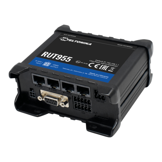
1 Introduction Thank you for purchasing a RUT905 router! RUT905 is part of the RUT9xx series of compact mobile routers with high speed wireless and Ethernet connections. This router is ideal for people who‘d like to share their internet on the go, as it is not restricted by a cumbersome cable connection. -
Page 11: Electrical, Mechanical & Environmental
2.4 Electrical, Mechanical & Environmental Dimensions (H x W x D) 80mm x 106mm x 46mm Weight 280g Power supply 100 – 240 VAC -> 9 VDC wall adapter Input voltage range 9 – 30VDC Power consumption <... -
Page 12: Setting Up Your Router
3 Setting up your router 3.1 Installation After you unpack the box, follow the steps, documented below, in order to properly connect the device. For better Wi-Fi performance, put the device in clearly visible spot, as obstacles such as walls and door hinder the signal. 1. -
Page 13: Logging In
4. Connect to the device wirelessly (SSID: Teltonika_Router) or use Ethernet cable and plug it into any LAN Ethernet port. 3.2 Logging in After you’re complete with the setting up as described in the section above, you are ready to start logging into your router and start configuring it. - Page 14 5. Select Internet Protocol Version 4 (TCP/IPv4) and then click 6. By default the router is going to have DHCP enabled, which Properties means that if you select “Obtain an IP address automatically” and “Obtain DNS server address automatically”, the router should lease you an IP and you should be ready to login.
- Page 15 Right click on the Wireless network icon and select Connect / Disconnect. A list should pop up with all available wireless networks. Select “Teltonika” and click connect.Then we launch our favorite browser and enter the routers IP into the address field: Press enter.
-
Page 16: Operation Modes
4 Operation Modes The RUT9xx series router supports various operation modes. It can be connected to the internet (WAN) via mobile, standard Ethernet cable or via a wireless network. When connecting to the internet, you may also backup your main WAN connection with one or two backup connections. Any interface can act like backup if configured so. At first router uses its main WAN connection, if it is lost then router tries to connect via backup with higher priority and if that fails too, router tries the second backup option. -
Page 17: Powering Options
5 Powering Options The RUT9xx router can be powered from power socket or over Ethernet port. Depending on your network architecture you can use LAN 1 port to power the device. RUT9xx can be powered from power socket and over Ethernet simultaneously. Power socket has higher priority meaning that the device will draw power from power socket as long as it is available. -
Page 18: Status
6 Status The status section contains various information, like current IP addresses of various network interfaces; the state of the routers memory; firmware version; DHCP leases; associated wireless stations; graphs indicating load, traffic, etc.; and much more. 6.1 Overview Overview section contains various information summaries. -
Page 19: System Information
Name of the router (hostname of the routers system). Can be changed in System -> Administration. 2. Host name Teltonika-RUT905.com Indicates how router will be seen by other devices on the network. Can be changed in System -> Administration. 3. Router Model Teltonika RUT905 Routers model. -
Page 20: Network Information
Memory explanation: Field Name Sample Value Explanation 86204 kB / 126556 kB 1. Free The amount of memory that is completely free. Should this rapidly (67%) decrease or get close to 0, it would indicate that the router is running out of memory, which could cause crashes and unexpected reboots. - Page 21 Cell ID 0684AAC ID of operator cell that device is currently connected to RSCP -53 dBm Ec/lo -5 dBm Operator LT BITE GSM Operator's name of the connected GSM network Operator state Registered (home) GSM network's status Connection type 3G (HSDPA) Indicates the GSM network's access technology Bytes received 5.2 MB (5500683...
- Page 22 6.3.1.3 LAN Display information about LAN connections. LAN information: Field Name Sample Value Explanation 1. Name LAN instance name 2. IP address 192.168.99.218 Address that the router uses on the LAN network. 3. Netmask 255.255.255.0 A mask used to define how large the LAN network is 4.
- Page 23 6.3.1.4 Wireless Wireless can work in two modes, Access Point (AP) or Station (STA). AP is when the wireless radio is used to create an Access Point that other devices can connect to. STA is when the radio is used to connect to an Access Point via WAN.
- Page 24 6.3.1.4.2 Access Point Display information about wireless connection (Access Point mode). Wireless AP information Field Name Sample Value Explanation 1. Channel 11 (2.46 GHz) The channel which is used to broadcast the SSID and to establish new connections to devices. 2.
- Page 25 This can either be the information of the Access Point that the router is connecting to in STA mode or a list of all devices that are connecting to the router in AP mode: Field Name Sample Value Explanation 1. MAC Address FC:C2:DE:91:36:A6 Associated station's MAC (Media Access Control) address 2.
- Page 26 6.3.1.7 OpenVPN Server Display OpenVPN connection information on server side. Field Name Sample Value Explanation 1. Enabled Yes/No OpenVPN status 2. Status Connected Connection status 2. Type Server A type of OpenVPN instance that has been created 3. IP 10.0.0.1 Remote virtual network's IP address 4.
- Page 27 6.3.1.9 VRRP VRRP (Virtual Router Redundancy Protocol) for LAN Field Name Sample Value Explanation 1. Status Enabled VRRP status 2. Virtual IP 192.168.1.253 Virtual IP address(- es) for LAN’s VRRP (Virtual Router Redundancy Protocol ) cluster 3. Priority Router with highest priority value on the same VRRP (Virtual Router Redundancy Protocol) cluster will act as a master, range [1 - 255] 4.
- Page 28 6.3.1.11 Access Display information about local and remote active connections status. Field Name Sample Value Explanation 1. Type SSH; HTTP; HTTPS Type of connection protocol 2. Status Disabled/Enabled Connection status 3. Port 22; 80; 443 Connection port used 4. Active 0(0.00B);0(0.00B);...
- Page 29 Field Name Sample Value Explanation 1. Type SSH; HTTP; HTTPS Type of connection protocol 2. Date 2016-03-03, 13:40:59 Date and time of connection 3. IP 192.168.2.10 IP address from which the connection was made 4. Authentications Failed/Succeed Status of authentication attempt Status...
-
Page 30: Device Information
6.4 Device information The page displays factory information that was written into the device during manufacturing process. Field Name Sample Value Explanation Serial number 77885555 Serial number of the device Product code RUT905001000 Product code of the device Batch number 1000 Batch number used during device’s manufacturing process Hardware revision... -
Page 31: Services
6.5 Services The page displays usage of the available services. 6.6 Routes The page displays ARP table and active IP routes of the device. 6.6.1 ARP Show the routers active ARP table. An ARP table contains recently cached MAC addresses of every immediate device that was communicating with the router. -
Page 32: Active Ip-Routes
6.6.2 Active IP-Routes Show the routers routing table. The routing table indicates where a TCP/IP packet, with a specific IP address, should be directed to. Field Name Sample Value Explanation 1. Network Interface to be used to transmit TCP/IP packets through 2. -
Page 33: Realtime Load
Field Name Sample Value Explanation 1. Connection type 3G (WCDMA) Type of mobile connection used 2. Signal -72 dBm Current signal strength value 3. Average -72.0 dBm Average signal strength value 4. Peak -72 dBm Peak signal strength value 6.7.2 Realtime Load This tri-graph illustrates average CPU load values in real time. - Page 34 Field Name Sample Value Explanation 1. 1/5/15 Minutes 0.83 Time interval for load averaging, colour of the diagram Load 2. Average 0.86 Average CPU load value over time interval (1/5/15 Minute) 3. Peak 1.50 Peak CPU load value of the time interval...
-
Page 35: Realtime Traffic
6.7.3 Realtime Traffic This graph illustrates average system inbound and outbound traffic over the course of ~3 minutes; each new measurement is taken every 3 seconds. The graph consists out of two colors coded graphs (green graph shows the outbound traffic, blue graph shows inbound traffic). Although not graphed, the page also displays peak loads and average of inbound and outbound traffic. -
Page 36: Realtime Wireless
6.7.4 Realtime Wireless Display the wireless radio signal, signal noise and theoretical maximum channel permeability. Average and peak signal levels are displayed. -
Page 37: Realtime Connections
6.7.5 Realtime Connections Displays currently active network connections with the information about network, protocol, source and destination addresses, transfer speed. -
Page 38: Mobile Traffic
6.8 Mobile Traffic Displays mobile connection data sent and received in KB of this day, week, Month. By default mobile traffic usage logging is disabled. To use this functionality is needed to enable it. Field Name Sample Value Explanation 1. Enable Enable/Disable Make a functionality active/inactive 2. -
Page 39: Speed Test
6.9 Speed Test Speed test is a tool for measuring your internet connection upload and download speeds. You can select servers for manual testing, or use auto test. -
Page 40: Events Log
6.10 Events Log Event log displays such actions as: login, reboot, firmware flashing and reset. 6.10.1 All Events Display all router events, their types and time of occurrence. -
Page 41: System Events
6.10.2 System Events Display all system events, their type and time of occurrence. Events include authentication or reboot requests, incoming and outgoing SMS and calls, Mails, Configuration changes, DHCP events. -
Page 42: Network Events
6.10.3 Network Events Display information about recent network events like connection status change, lease status change, network type or operator change. -
Page 43: Events Reporting
6.10.4 Events Reporting Allow to view, enable/disable or modify created rules for events reporting. 6.10.4.1 Events Reporting Configuration Allow to review created rules details and modify them, so after event occurrence, messages or emails are sent to specified address or phone numbers with information about the event. -
Page 44: Reporting Configuration
Field Name Sample Value Explanation 1. Enable Enable/Disable Make a rule active/inactive 2. Event type Reboot Select event type about which occurrence information will be sent 3. Event subtype After unexpected shut Specify event subtype to activate the rule down 4. - Page 45 6.10.5.1 Events Log Report Configuration Allow to change the configuration of periodic events reporting to email or FTP. FTP: Field Name Sample Value Explanation Enable Enable/Disable Make a rule active/inactive Events log System Events log for which the rule is applied Transfer type Events log file transfer type: Email/FTP Compress file...
- Page 46 Email: Field Name Sample Value Explanation Enable Enable/Disable Make a rule active/inactive Events log System Event log for which the rule is applied Transfer type Email Events log file transfer type: Email/FTP Compress file Enable Enable/disable compress events log file using gzip Subject Subject Subject of an email...
-
Page 47: Network
7 Network 7.1 Mobile 7.1.1 General 7.1.1.1 Mobile configuration Here you can configure mobile settings which are used when connecting to your local 3G network. Field Name Sample value Explanation Mode NAT / Passthrough NAT mode enables network address translation on router. Passthrough mode is similar with bridge mode except that in passthrough mode router do have internet connection. - Page 48 Password “password” Your password that you would use to connect to your carriers network. This field becomes available when you select an authentication method (i.e. authentication method is not “none”). These fields are always enabled on the alternate model. Service mode 2G only, 2G preferred, Your network preference.
-
Page 49: Sim Management
Perform a SIM card switch when network is denied 10. On data connection Enable/Disable Perform a SIM card switch when data connection fails fail * Your carrier's data usage accounting may differ. Teltonika is not liable should any accounting discrepancies occur. -
Page 50: Network Operators
7.1.3 Network Operators 7.1.3.1 Network Operators This function lets you Scan, Select and enter manual Network Operator to which router should connect. Function will provide great utility when router is in Roaming conditions. Operator is selected only for the active SIM card. In order to specify operator for the other SIM card it must first be selected as primary SIM in “SIM Management”. -
Page 51: Mobile Data Limit
3. Period Month/Week/Day Period for which mobile data limiting should apply 4. Start day/ Start hour A starting time for mobile data limiting period * Your carrier's data usage accounting may differ. Teltonika is not liable should any accounting discrepancies occur. -
Page 52: Sim Idle Protection
A phone number to send warning SMS message to, e.g. +37012345678 * Your carrier's data usage accounting may differ. Teltonika is not liable should any accounting discrepancies occur. 7.1.5 SIM Idle protection Some operators block user SIM cards after period of inactivity. This function enables router to periodically switch to secondary SIM card and establish data connection with mobile network in order to prevent SIM card blocking. -
Page 53: Wan
7.1.5.2 Test Tests the functioning of idle protection with your parameters entered at settings tab. Field Name Sample value Explanation 1. SIM SIM1 / SIM2 Displays SIM number 2. SIM state OK (inserted) Displays status of the SIM card 3. Host IP 8.8.8.8 Displays the IP of the Host 4. -
Page 54: Common Configuration
7.2.2 Common configuration Common configuration allows you to configure your TCP/IP settings for the wan network. You can switch between the Static, DHCP or PPPoE protocol by selecting the protocol that you want to use and then pressing Switch Protocol. 7.2.2.1 General Setup 7.2.2.1.1 Static: This is the configuration setup for when you select the static protocol. - Page 55 7.2.2.1.2 DHCP: When you select the DHCP protocol you can use it as is, because most networks will not require any additional advanced configuration. 7.2.2.1.3 PPPoE This protocol is mainly used by DSL providers: This is the configuration setup for when you select PPPoE protocol. Filed name Sample Explanation...
- Page 56 7.2.2.2.1 Static Field name Sample value Explanation 1. Disable NAT On/Off Toggle NAT on and off. Override MAC address 86:48:71:B7:E9:E4 Override MAC address of the WAN interface. If your ISP gives you a static IP address it might also bind it to your computers MAC address (i.e.
- Page 57 With this field you can alter the metric of that entry 6. Client ID to send when Specify client ID which will be sent when requesting DHCP requesting DHCP (Dynamic Host Configuration Protocol) 7. Vendor Class to send Specify vendor class which be sent when requesting DHCP when requesting DHCP (Dynamic Host Configuration Protocol) 8.
- Page 58 As you can see, the configuration is very similar to the static protocol; only in the example a 99th subnet is defined. Now if some device has an IP in the 99 subnet (192.168.99.xxx) and the subnets gateway metric is “higher” and the device is trying to reach the internet it will reroute it’s traffic not to the gateway that is defined in common configurations but through the one that is specified in IP aliases.
- Page 59 Field Name Sample value Explanation 1. Health monitor Interval Disable/5/10/20/30/60/120 The interval at which health checks are performed Seconds 2. Health monitor ICMP host(s) Disable/DNS Server(s) Where to Ping for a health check. As there is no /WAN GW/Custom definitive way to determine when the connection to internet is down for good, you’ll have to define a host whose availability that of the internet as a whole.
-
Page 60: Lan
7.3 LAN This page is used to configure the LAN network, where all your devices and computers that you connect to the router will reside. 7.3.1 Configuration 7.3.1.1 General Setup Field name Sample value Explanation 1. IP address 192.168.1.1 Address that the router uses on the LAN network IP netmask 255.255.255.0 A mask used to define how large the LAN network is... -
Page 61: Dhcp Server
7.3.2 DHCP Server The DHCP server is the router side service that can automatically configure the TCP/IP settings of any device that requests such a service. If you connect a device that has been configured to obtain IP address automatically the DHCP server will lease an IP address and the device will be able to fully communicate with the router. - Page 62 7.3.2.2 Advanced settings You can also define some advanced options that specify how the DHCP server will operate on your LAN network. Field Name Sample Value Explanation 1. Dynamic DHCP Checked/Unchecked Dynamically allocate client addresses, if set to only clients present in the ethers files are served...
- Page 63 7.3.2.4.2 Advanced Settings You may also optionally define a broadcast address and a custom DNS server.
-
Page 64: Wireless
Wi-Fi networks they will see your network with this name. Hide SSID – Will render your SSID hidden from other devices that try to scan the area. Connect to WRP100 automatically – let Teltonika WRP100 wireless repeater connect to this router automatically. - Page 65 7.4.1.1 Device 7.4.1.1.1 Advanced Settings Here you can configure more advanced parameters: Field name Sample value Explanation 1. Mode Auto, b, g, g+n Different modes provide different throughput and security options. 2. Country Code Any ISO/IEC 3166 alpha2 Selecting this will help the wireless radio configure its country code internal parameters to meet your countries wireless regulations.
- Page 66 First select an encryption method: TKIP, CCMP, TKIP&CCMP and auto. Note: Some authentication methods won’t support TKIP (and TKIP&CCMP) encryption. After you’ve selected your encryption method, you should enter your pass phrase, which must be at least 8 characters long. 7.4.1.2.2 MAC-Filter Filter –...
-
Page 67: Vlan
7.5 VLAN On this page you can configure your Virtual LAN settings, either Port based or Tag based. 7.5.1 VLAN Networks 7.5.1.1 VLAN Functionality Field Name Sample Value Explanation 1. VLAN mode Disabled / Port based / Lets user to choose the VLAN mode or disable VLAN functionality. Tag based 7.5.1.2 VLAN Network List If VLAN mode –... -
Page 68: Lan Networks
Specifies LAN interface name name 7.6 Firewall In this section we will look over the various firewall features that come with RUT905. 7.6.1 General Settings The routers firewall is a standard Linux iptables package, which uses routing chains and policies to facilitate... -
Page 69: Dmz
Field Name Sample value Explanation 1. Drop Invalid Checked/Unchecked A “Drop” action is performed on a packet that is determined to be invalid packets 2. Input Reject/Drop/Accept DEFAULT* action that is to be performed for packets that pass through the Input chain. -
Page 70: Port Forwarding
7.6.3 Port Forwarding Here you can define your own port forwarding rules. You can use port forwarding to set up servers and services on local LAN machines. The above picture shows how you can set up a rule that would allow a website that is being hosted on 192.168.1.109, to be reached from the outside by entering http://routersExternalIp:12345/. - Page 71 Field Name Sample value Explanation Name ENABLE_SSH_WAN_PASSTHROUGH Name of the rule. Used purely to make it easier to manage rules. Protocol TCP/UDP/TCP+ You may specify multiple by selecting (custom) and UDP/ICMP/Custom then entering protocols separated by space Source zone LAN/VPN/WAN Match incoming traffic from this zone only Source MAC address Match incoming traffic from these MACs only...
-
Page 72: Traffic Rules
7.6.4 Traffic Rules The traffic rule page contains a more generalized rule definition. With it you can block or open ports, alter how traffic is forwarded between LAN and WAN and many more things. Field Name Explanation Name Name of the rule. Used for easier rules management purpose only Protocol Protocol type of incoming or outgoing packet Source... - Page 73 Field Name Sample value Explanation Name “Allow-DHCP-Relay” Used to make rule management easier Restrict to address IPv4 and IPV6 Match traffic from selected address family only family Protocol TCP/UDP/Any/ICMP/Custom Protocol of the packet that is being matched against traffic rules. Match ICMP type Match traffic with selected ICMP type only Source zone...
- Page 74 7.6.4.1 Open Ports On the Router Field Name Sample value Explanation 1. Name Open_Port_rule Used to make rule management easier 2. Protocol TCP/UDP/Any/ICMP/Custom Protocol of the packet that is being matched against traffic rules. 3. External port 1-65535 Match incoming traffic directed at the given destination port or port range on this host.
- Page 75 Field Name Sample value Explanation 1. Name SNAT Used to make rule management easier 2. Protocol TCP/UDP/Any/ICMP/Custom Protocol of the packet that is being matched against traffic rules. 3. Source LAN/VPN/WAN Match incoming traffic from selected address family only 4. Destination LAN/VPN/WAN Forward incoming traffic to selected address family only 5.
-
Page 76: Custom Rules
address or IP range only Destination port Match forwarded traffic to the given destination port or port range only 10. SNAT IP address “10.101.1.10” Rewrite matched traffic to the given IP address 11. SNAT port “22” Rewrite matched traffic to the given source port. May be left empty to only rewrite the IP address' 12. - Page 77 Field Name Sample value Explanation Enable SYN flood protection Enable/Disable Makes router more resistant to SYN flood attacks. SYN flood rate “25” Set rate limit (packets/second) for SYN packets above which the traffic is considered a flood. SYN flood burst “50”...
- Page 78 7.6.6.3 SSH Attack Prevention Prevent SSH (Allows a user to run commands on a machine's command prompt without them being physically present near the machine.) attacks by limiting connections in defined period. Field Name Sample value Explanation Enable SSH limit Enable/Disable Enable SSH connections limit in selected period Limit period...
-
Page 79: Port Scan Prevention
7.6.6.5 HTTPS Attack Prevention Field Name Sample value Explanation Enable HTTPS limit Enable/Disable Limits HTTPS connections per period Limit period Second/Minute/Hour/Day Select in what period limit HTTPS connections Limit “10” Maximum HTTPS connections during the period Limit burst “10” Indicating the maximum burst 7.6.7 Port Scan Prevention 7.6.7.1 Port Scan Field Name... -
Page 80: Routing
7.6.7.2 Defending type Field Name Explanation SYN-FIN attack Protect from SYN-FIN attack SYN-RST attack Protect from SYN-RST attack X-Mas attack Protect from X-Mas attack FIN scan Protect from FIN scan NULLflags attack Protect from NULLflags attack 7.7 Routing 7.7.1 Static Routes Static routes specify over which interface and gateway a certain host or network can be reached. -
Page 81: Dynamic Routes
Field name Value Explanation 1. Routing table MAIN/WAN/WAN2/WAN3 Defines the table to use for the route 2. Interface MAIN/WAN/WAN2/WAN3 The zone where the target network resides 3. Destination address IP address The address of the destination network 4. Netmask IP mask Mask that is applied to the Target to determine to what actual IP addresses the routing rule applies 5. - Page 82 7.7.2.2 OSPF Protocol 7.7.2.2.1 OSPF General Instance Field name Value Explanation 1. Enable Enable/Disable Enables OSPF protocol 2. Stub Enable/Disable Enable/Disable stub 3. RFC1583 Enable/Disable Enables OSPF compatibility with RFC1583 specification compatibility 4. Import All/None/custom Set if the protocol must import routes 5.
- Page 83 Field name Value Explanation 1. Enabled Enable/Disable Enable specific OSPF area 2. Stub Enable/Disable Enable/disable stub 3. Interface br-lan A interface that new instance will have 4. New IP Name of the new OSPF network configuration. Used for easer configurations management purpose only 7.7.2.3 General Protocol...
-
Page 84: Load Balancing
Field name Value Explanation 1. Enable Enable/Disable Enable/Disable settings 2. Learn Enable/Disable Enables routes learning 3. Persist Enable/Disable If checked it allows to store routes. After a restart, routes will be still configured 4. Scan time Time between scans 5. Import Set if the protocol must import routes 6. -
Page 85: Services
8 Services 8.1 VRRP 8.1.1 VRRP LAN Configuration Settings Field name Sample Explanation 1. Enable Enable/Disable Enable VRRP (Virtual Router Redundancy Protocol) for LAN 2. IP address 192.168.1.253 Virtual IP address for LAN's VRRP (Virtual Router Redundancy Protocol) cluster 3. Virtual ID Routers with same IDs will be grouped in the same VRRP (Virtual Router Redundancy Protocol) cluster, range [1-255] 4. -
Page 86: Parameters Configuration
8.2 TR-069 TR-069 is a standard developed for automatic configuration and management of remote devices by Auto Configuration Servers (ACS). 8.2.1 TR-069 Parameters Configuration Field name Sample Explanation 1. Enable Enable/Disable Enable TR-069 client 2. Enable Periodic Transmission Enable / Disable Enable periodic transmissions of data to server 3. -
Page 87: Proxy Based Content Blocker
Field name Sample Explanation 1. Enable Enable/Disable Enable host name based websites blocking 2. Mode Whitelist/Blacklist Whitelist - allow every site on the list and block everything else. Blacklist - block every site on the list and allow everything else. 3. -
Page 88: Ntp
8.4 NTP NTP configuration lets you setup and synchronize routers time. Field name Description 1. Current System time Local time of router. 2. Time zone Time zone of your country. 3. Enable NTP Enable system’s time synchronization with time server using NTP (Network Time Protocol) 4. -
Page 89: Rs232/Rs485
8.5 RS232/RS485 RS232 and RS485 functions are designed to utilize available serial interfaces of the router. Serial interfaces provide possibility for legacy devices to gain access to IP networks. 8.5.1 RS232 Field name Sample Explanation 1. Enabled Enable/Disable Check the box to enable the serial port function. 2. - Page 90 8.5.1.1 RS232 connector pinout RS232 connector type on this device is DCE female. DCE stands for Data Communication Equipment. Name* Description* Direction on this device Data Carrier Detect Output Receive Data Output Transmit Data Input Data Terminal Ready Input Signal Ground Data Set Ready Output Ready To Send...
-
Page 91: Rs485
8.5.2 RS485 RS-485 is differential serial data transmission standart for use in long ranges or noisy environments. Field name Sample Explanation 1. Enabled Enable/Disable Check the box to enable the serial port function. 2. Baud rate 300 / 115200 Selectthe communication speed of the serial interface. 3. - Page 92 Twisted pair is the prefered cable for RS-485 networks. Twisted pair cables picks up noise and other electromagnetically induced voltages as common mode signals, which are rejected by the differential receivers. 8.5.2.2 Cable type Recomended cable parameters: Parameter Value Cable Type 22-24 AWG, 2 –...
- Page 93 Example 2-wire network electrical connection: to enable 2-wire RS-485 configuration in Teltonika router, you need to connect D_P to R_P and D_N to R_N at the device RS-485 socket. Termination resistors are placed at each cable end. 8.5.2.5 Termination When to use (place jumper) Termination resistor, equal in resistance to cable characteristic impedance, must be connected at each end of the cable to reduce reflection and ringing of the signals when the cable lengths get relatively long.
-
Page 94: Modes Of Different Serial Types In Rs232 And Rs485
8.5.2.6 Number of devices in RS-485 Network One RUT9xx RS-485 driver is capable of driving maximum 32 receivers, provided that receiver input impedance is 12kΩ. If receiver impedances are higher, maximum number of receivers in network increases. Any combination of receiver types can be connected together, provided their parallel impedance does not exceed R >... - Page 95 Field name Explanation 1. Protocol Select which protocol to use for data transmission 2. Mode Select mode to apply for router. Server - wait for incoming connection. Client - initiate the connection. Bidirect – On default acts like client, but at the same time waits for incoming connections.
- Page 96 Bidirect: Bidirect mode allows bi-directional communication through serial interface. In default state application acts like client, but at the same time, listens to any incoming connections on dedicated port. When there is connection incoming the application drops current connection to remote server and acts like a server to the new connection. This triggers configured output change, which can be used to inform any auxiliary devices about connection status change.
- Page 97 8.5.3.3 Modem mode In this mode the router imitates dial-up modem. Connection to TCP/IP network can be established using AT commands. The connection can be initiated by the device connected via serial interface with ATD command: ATD<host>:<port>. If Direct connect settings are specified the connection to the server is always active. Data mode can be entered by issuing ATD command.
-
Page 98: Vpn
VPN (Virtual Private Network) is a method for secure data transfer through unsafe public network. This section explains how to configure OpenVPN, which is implementation of VPN supported by the RUT905 router. A picture below demonstrates default OpenVPN configurations list, which is empty, so you have to define a new configuration to establish any sort of OpenVPN connection. - Page 99 There can be multiple server/client instances. You can set custom settings here according to your VPN needs. Below is summary of parameters available to set: Field name Explanation Enabled Switches configuration on and off. This must be selected to make configuration active. TUN/TAP Selects virtual VPN interface type.
-
Page 100: Ipsec
generate less network traffic; however, this means higher router CPU loads. Use it carefully with high rate traffic or low CPU resources. Encryption Selects Packet encryption algorithm. Authentication Sets authentication mode, used to secure data sessions. Two possibilities you have here: “Static key”... - Page 101 IPsec system maintains two databases: Security Policy Database (SPD) which defines whether to apply IPsec to a packet or not and specify which/how IPsec-SA is applied and Security Association Database (SAD), which contain Key of each IPsec-SA. The establishment of the Security Association (IPsec-SA) between two peers is needed for IPsec communication. It can be done by using manual or automated configuration.
- Page 102 Detection Pre shared key A shared password to authenticate between the peer Remote VPN Domain name or IP address. Leave empty or any endpoint Remote network secure group IP address and mask used to determine to address/Subnet what subnet an IP address belongs to. Range [0-32]. IP should differ from mask device LAN IP 10.
-
Page 103: Gre Tunnel
8.6.3 GRE Tunnel GRE (Generic Routing Encapsulation RFC2784) is a solution for tunneling RFC1812 private address-space traffic over an intermediate TCP/IP network such as the Internet. GRE tunneling does not use encryption it simply encapsulates data and sends it over the WAN. In the example network diagram two distant networks LAN1 and LAN2 are connected. - Page 104 Field name Explanation Enabled Check the box to enable the GRE Tunnel function. Remote endpoint IP address Specify remote WAN IP address. Remote network IP address of LAN network on the remote device. Remote network netmask Network of LAN network on the remote device. Range [0-32]. Local tunnel IP Local virtual IP address.
-
Page 105: Pptp
8.6.4 PPTP Point-to-Point Tunneling Protocol (PPTP) is a protocol (set of communication rules) that allows corporations to extend their own corporate network through private "tunnels" over the public Internet. Effectively, a corporation uses a wide-area network as a single large local area network. A company no longer needs to lease its own lines for wide-area communication but can securely use the public networks. -
Page 106: L2Tp
Field name Explanation 1. Enable Enable current configuration 2. Use as default gateway Use this PPTP instance as default gateway 3. Server The server IP address or hostname 4. Username The user name for authorization with the server 5. Password The password for authorization with the server 8.6.5 L2TP Allows setting up a L2TP server or client and should it be needed - using it with IPsec (L2TP/IPSec). -
Page 107: Dynamic Dns
8.7 Dynamic DNS Dynamic DNS (DDNS) is a domain name service allowing to link dynamic IP addresses to static hostname. To start using this feature firstly you should register to DDNS service provider (example list is given in description). You are provided with add/delete buttons to manage and use different DDNS configurations at the same time! You can configure many different DDNS Hostnames in the main DDNS Configuration section. -
Page 108: Sms Utilities
Time interval (in minutes) to force IP address renew. 8.8 SMS Utilities RUT905 has extensive amount of various SMS Utilities. These are subdivided into 6 sections: SMS Utilities, Call Utilities, User Groups, SMS Management, Remote Configuration and Statistics. 8.8.1 SMS Utilities All configuration options are listed below: You can choose your SMS Keyword (text to be sent) and authorized phone number in the main menu. - Page 109 Monitoring status Field name Explanation Notes Reboot Enable This check box will enable and Allows router restart via SMS. disable SMS reboot function. Action The action to be performed when this rule is met. SMS text SMS text which will reboot SMS text can contain letters, numbers, spaces and router.
- Page 110 connection status via SMS. separate SMS Rule and an option under SMS Reboot rule. Action The action to be performed when this rule is met. Enable SMS Status This check box will enable and SMS status is disabled by default. disable SMS status function.
- Page 111 Allowed users Whitelist of allow users From all numbers, from group or from single number. Write to config Permanently saves mobile With this setting enabled, router will keep mobile network state. state even after reboot. If it is not selected, router will revert mobile state after reboot.
- Page 112 Important Notes: 3G settings must be configured correctly. If SIM card has PIN number you must enter it at “Network” > “3G” settings. Otherwise SMS reboot function will not work. Sender phone number must contain country code. You can check sender phone number format by reading the details of old SMS text massages you receiving usually.
- Page 113 SMS text SMS text which will turn Web SMS text can contain letters, numbers, spaces and access ON/OFF. special symbols. Capital letters also matters. Authorization method What kind of authorization to No authorization, by serial or by router admin use for SIM management. password.
- Page 114 disable this function. Action The action to be performed Router will reboot after this rule is executed. when this rule is met. SMS text SMS text which will force router SMS text can contain letters, numbers, spaces and to upgrade configuration from special symbols.
-
Page 115: Call Utilities
Mobile data ON/OFF. Only thing that is needed is to call routers SIM card number from allowed phone (user) and RUT905 will perform all actions that are assigned for this particular number. To configure new action on call rules you just need to click the Add button in the „New Call rule”... -
Page 116: Sms Management
Field name Sample Explanation 1. Group name Group1 Name of grouped phone numbers 2. Phone number +37061111111 Number to add to users group, must match international format. You can add phone numbers fields by clicking on the green + symbol 8.8.4 SMS Management 8.8.4.1 Read SMS In SMS Management page Read SMS you can read and delete received/stored SMS. - Page 117 8.8.4.2 Send SMS Field name Sample Explanation 1. Phone number +3701111111 Recipients phone number. Should be preceded with country code, i.e. “+370” 2. Message My text. Message text, special characters are allowed. 8.8.4.3 Storage With storage option you can choose for router NOT to delete SMS from SIM card. If this option is not used, router will automatically delete all incoming messages after they have been read.
-
Page 118: Remote Configuration
It should not, generally, be used if you have high cost per SMS. This is especially relevant if you will try to send whole OpenVPN configuration, which might acumulate ~40 SMS. 8.8.5.1 Receive configuration This section controls how configuration initiation party should identify itself. In this scenario RUT905 itself is being configured. Field name... - Page 119 Field name Values Notes Generate SMS New/From current Generate new SMS settings or use current device configuration configuration Interface Mobile/Wired Interface type used for WAN (Wide Area Network) connection Enable/Disable Include configuration for WAN (Wide Area Network) Enable/Disable Include configuration for LAN (Local Area Network) Protocol Static/DHCP Network protocol used for network configuration...
- Page 120 to receive datagrams. 13. Primary SIM card SIM1/SIM2 A SIM card that will be used as primary 14. Mobile connection Use pppd mode An underlying agent that will be used for mobile data Use ndis mode connection creation and management 15.
-
Page 121: Statistics
By router admin password 8.8.6 Statistics In statistics page you can review how much SMS was sent and received on both SIM card slots. You can also reset the counters. 8.9 SNMP SNMP settings window allows you to remotely monitor and send GSM event information to the server. 8.9.1 SNMP Settings Field name Sample... -
Page 122: Trap Settings
Variables/OID Description 1.3.6.1.4.1.99999.1.1.1 Modem IMEI 1.3.6.1.4.1.99999.1.1.2 Modem model 1.3.6.1.4.1.99999.1.1.3 Modem manufacturer 1.3.6.1.4.1.99999.1.1.4 Modem revision 1.3.6.1.4.1.99999.1.1.5 Modem serial number 1.3.6.1.4.1.99999.1.1.6 SIM status 1.3.6.1.4.1.99999.1.1.7 Pin status 1.3.6.1.4.1.99999.1.1.8 IMSI 1.3.6.1.4.1.99999.1.1.9 Mobile network registration status 10. 1.3.6.1.4.1.99999.1.1.10 Signal level 11. 1.3.6.1.4.1.99999.1.1.11 Operator currently in use 12. -
Page 123: Sms Gateway
Field name Sample Explanation 1. SNMP Trap Enable/Disable Enable SNMP (Simple Network Management Protocol) trap functionality 2. Host/IP 192.168.99.155 Host to transfer SNMP (Simple Network Management Protocol) traffic to 3. Port Port for trap's host 4. Community Public/Private The SNMP (Simple Network Management Protocol) Community is an ID that allows access to a router's SNMP data 8.10 SMS Gateway 8.10.1 Post/Get Configuration... - Page 124 8.10.1.2 Syntax of HTTP POST/GET string HTTP POST/GET string Explanation http://{IP_AD /cgi-bin/sms_read? Read message DRESS} username={your_user_name}&password={your_password}&number={MESSAG E_INDEX} /cgi-bin/sms_send? Send message username={your_user_name}&password={your_password}&number={PHONE_ NUMBER}&text={MESSAGE_TEXT} /cgi-bin/sms_delete? Delete message username={your_user_name}&password={your_password}&number={MESSAG E_INDEX} /cgi-bin/ sms_list? username={your_user_name}&password={your_password} List all messages /cgi-bin/sms_ total? username={your_user_name}&password={your_password} Number of messages in memory Note: parameters of HTTP POST/GET string are in capital letters inside curly brackets.
-
Page 125: Email To Sms
8.10.2 Email to SMS Field name Values Notes 1. Enable Enable/Disable Allows to convert received Email to SMS 2. POP3 server “pop.gmail.com” POP3 server address 3. Server port “995” Server authentication port 4. User name “admin” User name using for server authentication 5. -
Page 126: Auto Reply Configuration
8.10.3.1 Scheduled Messages Configuration Field name Values Notes 1. Enable Enable/Disable Activates periodical messages sending. 2. Recipient’s phone “+37060000001” Phone number that will receive messages. number 3. Message text “Test” Message that will be send. 4. Message sending Day/Week/Month/Year Message sending period. interval 8.10.4 Auto Reply Configuration Auto reply allows replying to every message that router receives to everyone or to listed numbers only. -
Page 127: Sms Forwarding
8.10.5 SMS Forwarding 8.10.5.1 SMS Forwarding To HTTP This functionality forwards mobile messages from all or only specified senders to HTTP, using either POST or GET methods. Field name Values Notes 1. Enable Enable / Disable Enable mobile message forwarding to HTTP 2. - Page 128 8.10.5.2 SMS Forwarding to SMS This functionality allows forwarding mobile messages from specified senders to one or several recipients. Field name Values Notes 1. Enable Enable / Disable Enable mobile message forwarding 2. Add sender number Enable / Disable If enabled, original senders number will be added at the end of the forwarded message 3.
-
Page 129: Smpp
If enabled, original senders number will be added at the end of the forwarded message Subject “forwarded message” Text that will be inserted in email Subject field SMTP server mail.teltonika.lt Your SMTP server’s address SMTP server port Your SMTP server’s port number Secure connection Enable / Disable... -
Page 130: General Settings
8.11.1 General settings 8.11.1.1 Main settings Field name Explanation Enabled Check this flag to enable hotspot functionality on the router. AP IP Access Point IP address. This will be the address of the router on the hotspot network. The router will automatically create a network according to its own IP and the CIDR number that you specify after the slash. - Page 131 UAM port Port to bind for authenticating clients UAM UI port UAM UI port UAM secret Shared secret between UAM server an hotspot NAS Identifier NAS Identifier Swap octets Swap the meaning of input octets and output as it related to RADIUS attributes Location name The name of location Authentication mode: Internal radius/Without radius...
-
Page 132: Internet Access Restriction Settings
8.11.2 Internet Access Restriction Settings Allows disable internet access on specified day and hour of every week. 8.11.3 Logging 8.11.3.1 Configuration Field name Explanation 1. Enable Check this box if you want to enable wireless traffic logging. This feature will produce logs which contain data on what websites each client was visiting during the time he was connected to your hotspot. - Page 133 Field name Explanation 1. Mode The mode of the schedule. Use “Fixed” if you want the uploading to be done on a specific time of the day. Use “Interval” if you want the uploading to be done at fixed interval. 2.
-
Page 134: Landing Page
8.11.4 Landing Page 8.11.4.1 General Landing Page Settings With this functionality you can customize your Hotspot Landing page. Field name Explanation 1. Page title Will be seen as landing page title 2. Theme Landing page theme selection 3. Upload login page Allows to upload custom landing page theme 4. -
Page 135: Radius Server Configuration
8.11.4.2 Template In this page you can review landing page template HTML code and modify it. 8.11.5 Radius server configuration An authentication and accounting system used by many Internet Service Providers (ISPs). When you dial in to the ISP you must enter your username and password. This information is passed to a RADIUS server, which checks that the information is correct, and then authorizes access to the ISP system. -
Page 136: Statistics
Field name Explanation 1. Enable Activates an authentication and accounting system 2. Remote access Activates remote access to radius server 3. Accounting port Port on which to listen for accounting 4. Authentication port Port on which to listen for authentication 8.11.6 Statistics On hotspot statistics page you can review statistical information about hotspot instances. -
Page 137: Auto Reboot
8.13 Auto Reboot 8.13.1 Ping Reboot Ping Reboot function will periodically send Ping command to server and waits for echo receive. If no echo is received router will try again sending Ping command defined number times, after defined time interval. If no echo is received after the defined number of unsuccessful retries, router will reboot. -
Page 138: Periodic Reboot
8.13.2 Periodic Reboot Field name Explanation 1. Enable This check box will enable or disable Periodic reboot feature. 2. Days This check box will enable router rebooting at the defined days. 3. Hours, Minutes Uploading will be done on that specific time of the day 8.14 UPNP 8.14.1 General Settings UPnP allows clients in the local network to automatically configure the router. -
Page 139: Advanced Settings
8.14.2 Advanced Settings Field name Explanation 1. Use UPnP port mapping Enable UPnP port mapping functionality 2. Use NAT-PMP port Enable NAT-PMP mapping functionality mapping 3. Device UUID Specify Universal unique ID of the device 8.14.3 UPnP ACLs ACLs specify which external ports may be redirected to which internal addresses and ports. Field name Explanation 1. -
Page 140: Qos
8.15 QoS QoS (Quality of Service) is the idea that transmission rates, error rates, and other characteristics can be measured, improved, and, to some extent, guaranteed in advance. QoS is of particular concern for the continuous transmission of high-bandwidth video and multimedia information. QoS can be improved with traffic shaping techniques such as packet, network traffic, and port prioritization. -
Page 141: Network Shares
8.16 Network Shares 8.16.1 Mounted File Systems On this page you can review mounted file systems (for example USB flashdrive). Field name Explanation 1. File System Filesystem on which additional file system is mounted 2. Mount Point Directory available for mounting additional file system 3. -
Page 142: Samba User
Field name Values Notes Enable Enable / Disable Enables Samba service Hostname Router_Share Name of samba server Description Teltonika_Router_Share Short server description Workgroup WORKGROUP Name of the workgroup In Shared Directories section you can add directories to be shared and configure some usage parameters: Field name Values Notes... -
Page 143: Input/Output
8.17 Input/Output 8.17.1 Status In this page you can review the current state of all router’s inputs and outputs. 8.17.2 Input Allows you to set up input parameters and specify what actions should be taken after triggering event of any input. - Page 144 In the input rules section you can create and modify the rules for action after specific input triggering. Field name Sample Explanation Type Digital/Digital isolated/Analog Specifies input type Triger Input open Specifies for which trigger rule is applied Action Send SMS Specifies what action is done Enable Enable/Disable...
- Page 145 Field name Values Explanation Input type Digital/Digital isolated/Analog Specify input type Triger Input open / Input shorted/ both Specify for which trigger rule will be applied Action Send SMS/ Change SIM card/ Send email/ Choose what action will be done after input Change profile/ Turn WiFi ON or OFF/Reboot/ triggering Output...
-
Page 146: Output
Action is Send email SMTP server Specify SNMP server port. Only shown when Action is Send email port Secure Enable/Disable Specify if server support SSL or TLS. Only shown when Action is Send connection email User name username Specify user name to connect SNMP server. Only shown when Action is Send email Password password... - Page 147 8.17.3.2 ON/OFF Field name Sample Explanation Digital OC output Turn on / Turn Off Manually toggle Digital OC output Digital relay output Turn on / Turn Off Manually toggle Digital relay output 8.17.3.3 Post/Get Configuration Field name Sample Explanation Enable Enable /Disable Enable POST/GET output functionality Username...
- Page 148 8.17.3.6 Periodic Control Periodic control function allows user to set up schedule by which the outputs are either turned ON or OFF at specific time. After clicking on ADD button (Or Edit, if the rule is already created) you get the second periodic output configuration page with extra parameters to set.
-
Page 149: Input/Output Hardware Information
8.17.3.7 Scheduler This function allows you to set up the periodical, hourly schedule for the outputs. You can select on which week days the outputs are going to be on or off. 8.17.4 Input/Output hardware information The Input/output (I/O) connector is located in the front panel next to LEDs. Pin-out of the I/O connector: Type Description Ratings... - Page 150 8.17.4.1 Digital input for passive sensors Absolute maximum ratings: Maximum voltage on input pin1 with respect to pin6: 3V Minimum voltage on input pin1 with respect to pin6: 0V The input is protected from short positive or negative ESD transients This input is designed for connecting sensors with passive output (not outputting voltage) such as: Passive infrared (PIR) sensors for motion detection (sensors with open collector or relay output are suitable type to use )
- Page 151 Example schematic of using PIR sensors, mechanical switches, reed switches: Example schematic of connecting multiple sensors with open collector outputs: Multiple sensors can be connected in parallel like in the schematic below. In this configuration any sensor will activated the input. The example could be multiple motion sensors located in multiple places. If either of them will sense motion, the configured event (for e.g.
- Page 152 8.17.4.2 Digital galvanically isolated input Sensors with push-pull output stage can be connected to this input. Example of such circuit is shown in the picture below. The circuit uses optocoupler to isolate the input. In case of the failure at the input, the rest of the circuit remains safe.
- Page 153 Input electrical characteristics: Parameter Value Maximum voltage Minimum voltage Resolution 5.859mV Input low-pass filter cut-off frequency (-3dB) 10Hz Input resistance (seen between I/O header pins 9 and 6 ) 131kΩ Input accuracy: Input voltage range, V Measurement error, % 0 <Vin≤ 1 <20 1 <Vin≤...
- Page 154 Output can be also used to generate signals with desired amplitude. Resistor could be for example 4.7kΩ. 8.17.4.5 Relay output Relay output has two pins: COM and NO. When the relay is not energized (output not active), these pins are disconnected.
-
Page 155: System
9 System 9.1 Configuration Wizard The configuration wizard provides a simple way of quickly configuring the device in order to bring it up to basic functionality. The wizard is comprised out of 4 steps and they are as follows: Step 1 (General change) First, the wizard prompts you to change the default password. - Page 156 Step 3 (LAN) Next, you are given the chance to configure your LAN and DHCP server options. For a detailed explanation see LAN under Network. Step 4 (Wi-Fi) The final step allows you to configure your wireless settings in order to set up a rudimentary Access Point. When you’re done with the configuration wizard, press Save.
-
Page 157: Profiles
9.2 Profiles Router can have 5 configuration profiles, which you can later apply either via WebUI or via SMS. When you add New Profile, you save current full configuration of the router. Note: profile names cannot exceed 10 symbols. 9.3 Administration 9.3.1 General... -
Page 158: Troubleshoot
Field name Explanation Router name Enter your new router name. Host name Enter your new host name New Password Enter your new administration password. Changing this password will change SSH password as well. Confirm new password Re-enter your new administration password. Language Website will be translated into selected language. -
Page 159: Backup
1. Backup archive Download current router settings file to personal computer. This file can be loaded to other RUT905 with same Firmware version in order to quickly configure it. 2. Restore from backup Select, upload and restore router settings file from personal computer. - Page 160 9.3.3.1 Access control 9.3.3.1.1 General Field name Explanation Enable SSH access Check box to enable SSH access. Remote SSH access Check box to enable remote SSH access. Port Port to be used for SSH connection Enable HTTP access Enables HTTP access to router Enable remote HTTP Enables remote HTTP access to router access...
-
Page 161: Diagnostics
9.3.3.1.2 Safety Field name Explanation 1. SSH access secure Check box to enable SSH access secure functionality. enable 2. Clean after reboot If check box is selected – blocked addresses are removed after every reboot. 3. Fail count Specifies maximum connection attempts count before access blocking. 4. -
Page 162: Mac Clone
Field name Explanation 1. Host Enter server IP address or hostname. 2. Ping Utility used to test the reach ability of a host on an Internet IP network and to measure the round-trip time for messages sent from the originating host to a destination server. Server echo response will be shown after few seconds if server is accessible. -
Page 163: Monitoring
Field name Explanation Mobile Check box to show Mobile table in Overview page SMS counter Check box to show SMS counter table in Overview page System Check box to show System table in Overview page Wireless Check box to show Wireless table in Overview page Check box to show WAN table in Overview page Local network Check box to show Local network table in Overview page... -
Page 164: User Scripts
9.4 User scripts Advanced users can insert their own commands that will be executed at the end of booting process. In Script Management window is shown content of a file /etc/rc.local. This file is executed at the end of startup, executing the line: sh /etc/rc.local. -
Page 165: Firmware
9.6 Firmware 9.6.1 Firmware Keep all settings – if the check box is selected router will keep saved user configuration settings after firmware upgrade. When check box is not selected all router settings will be restored to factory defaults after firmware upgrade. When upgrading firmware, you can choose settings that you wish to keep after the upgrade. -
Page 166: Fota
9.6.2 FOTA Field name Explanation 1. Server address Specify server address to check for firmware updates. E.g. “http://teltonika.sritis.lt/rut9xx_auto_update/clients/” 2. User name User name for server authorization. 3. Password Password name for server authorization. 4. Enable auto check Check box to enable automatic checking for new firmware updates. -
Page 167: Device Recovery
The following section describes available options for recovery of malfunctioning device. Usually device can become unreachable due to power failure during firmware upgrade or if its core files were wrongly modified in the file system. Teltonika’s routers offer several options for recovering from these situations. 10.1 Reset button Reset button is located on the back panel of the device. -
Page 168: Glossary
11 Glossary: WAN – Wide Area Network is a telecommunication network that covers a broad area (i.e., any network that links across metropolitan, regional, or national boundaries). Here we use the term WAN to mean the external network that the router uses to reach the internet. LAN –... - Page 169 TKIP – Temporal Key Integrity Protocol – scrambles the keys using hashing algorithmand, by adding an integrity- checking feature, ensure that the keys haven’t been tampered with. CCMP – Counter Mode Cipher Block Chaining Message Authentication Code Protocol – encryption protocol designed for Wireless LAN products that implement the standards of the IEEE 802.11i amendment to the original IEEE802.11 standard.
Need help?
Do you have a question about the RUT905 and is the answer not in the manual?
Questions and answers