Table of Contents
Advertisement
Advertisement
Chapters
Table of Contents

Related Manuals for American-Lincoln 7765 56514750


Summary of Contents for American-Lincoln 7765 56514750
- Page 1 7765 Instructions for Use Instrucciones de uso American-Lincoln Models: 56514750 , 56514851 (VD Gas) (VD LP) 56514853 , 56514855 , 56514856 (VD Diesel) (MD Gas) (MD LP GM3.0L) 56514857 , 56514858 (MD Diesel S4Q2) (VD LP) A-English B-Español 3/08 revised 4/08 Form No. 56041713...
-
Page 2: Table Of Contents
A-2 / ENGLISH TABLE OF CONTENTS Page Table of Contents ..............A-2 - A-3 Introduction .................. A-4 Introduction ................A-4 Parts and Service ..............A-4 Nameplate ................A-4 Un-Crating ................A-4 Machine Operation ..............A-5 Preparing the Machine for Operation........A-5 Cautions and Warnings............... A-6 Consignes De Prudence Et De Securite ........A-7 Operation of Controls and Gauges .........A-8 –... -
Page 3: Table Of Contents
ENGLISH / A-3 TABLE OF CONTENTS Page Scrubbing System Operating Instructions ....A-16 – A-18 ESP System Operating Instructions ........A-16 ESP Recycling Control Panel ..........A-16 ESP Recycling System On/Off Switch ........A-16 Solution High Warning Light ..........A-16 Detergent Low Warning Light ..........A-16 Detergent Flow Knob ............A-16 The Scrubbing System - How It Works .......A-17 Non-Recycling Scrubbing System - How It Works ....A-17... -
Page 4: Introduction
A-4 / ENGLISH INTRODUCTION This manual will help you get the most from your American-Lincoln sweeper / scrubber. Read it thoroughly before operating the machine. PARTS AND SERVICE Repairs, when required, should be performed by your Authorized American-Lincoln Service Center, who employs factory trained service ™... -
Page 5: Machine Operation
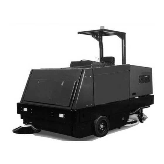
ENGLISH / A-5 MACHINE OPERATION FIGURE 1 YOUR 7765 MACHINE HAS BEEN SHIPPED COMPLETE, BUT DO NOT ATTEMPT TO OPERATE WITHOUT FOLLOWING THESE INSTRUCTIONS. PREPARING THE MACHINE FOR OPERATION Connect and tighten battery cables. Fill the tank with REGULAR GRADE unleaded gasoline; Diesel fuel if equipped with diesel engine. WARNING Never fi... -
Page 6: Cautions And Warnings
• This machine is not suitable for picking up hazardous dust. • Use care when using scarifi er discs and grinding stones. American-Lincoln will not be held responsible for any damage to fl oor surfaces ™ caused by scarifi ers or grinding stones. -
Page 7: Consignes De Prudence Et De Securite
• Cette machine n’est pas conçue pour le ramassage des poussières dangereuses. • Faites extrêmement attention lorsque vous utilisez des disques de scarifi cateur et des meules. American-Lincoln ne pourra, en aucun cas, être tenu ™ pour responsable des dommages occasionnés à vos sols par ce type d’équipement. -
Page 8: Operation Of Controls And Gauges
A-8 / ENGLISH OPERATIONS OF CONTROLS AND GAUGES Water Temperature Gauge Check Engine Light (Gasoline/LP) Hour Meter Turn Signal Fuel Gauge Throttle Diesel Oil Pressure Gauge Throttle Gasoline/LP Volt Meter Solution Control Main Broom Switch Sweeping Broom Lift Control Side Broom Switch ESP Option Dust Control Switch AA Detergent Flow Knob... -
Page 9: Turn Signal (Option
ENGLISH / A-9 OPERATIONS OF CONTROLS AND GAUGES 4-WAY TURN SIGNAL (OPTION) The Turn Signal Option (U) is located on the steering column and works as automotive turn signals work, forward on the lever for right and back on the lever for left. The 4-way fl asher will activate when the turn signal lever is pulled out. GLOW PLUG SWITCH (DIESEL) Under no circumstances should any other unauthorized starting aids be used at the same time as Glow Plugs. -
Page 10: Main Broom Switch
A-10 / ENGLISH OPERATIONS OF CONTROLS AND GAUGES MAIN BROOM SWITCH The Main Broom Switch (F) is located on the console to the right of the steering wheel in the SWEEPING section. This switch will activate the Main Broom. This switch has two positions “ON” and “OFF”. See Sweeping Broom Lift Control. SIDE BROOM SWITCH (OPTION FOR MANUAL DUMP MACHINES) The Side Broom Switch (G) is located on the console to the right of the steering wheel in the SWEEPING section. -
Page 11: Water Temperature Gauge
ENGLISH / A-11 OPERATIONS OF CONTROLS AND GAUGES WATER TEMPERATURE GAUGE The Water Temperature Gauge (A) is located on the console panel above the steering wheel in the gauge cluster. The gauge is mechanical and activated by a sender in the engine. It displays the engine coolant temperature in Fahrenheit. HOUR METER The Hour Meter (B) is located on the console panel above the steering wheel in the gauge cluster. -
Page 12: Scrub Brushes Switch
A-12 / ENGLISH OPERATIONS OF CONTROLS AND GAUGES SCRUB BRUSHES SWITCH The Brushes Switch (AK) is located on the console to the left of the steering wheel in the “SCRUBBING” section. This switch in the position marked “LOWER” will lower the scrub brush deck and activate the three scrub brushes. The Brush Rotation Switch (AM) and the Brush Pressure Switch (AJ) can not be activated unless this switch is in the “LOWER”... -
Page 13: Hopper Lift
ENGLISH / A-13 OPERATIONS OF CONTROLS AND GAUGES HOPPER LIFT - (VARIABLE MACHINES ONLY) The Hopper Lift Lever (AF) is located to the left of the steering wheel on the left side of the driver compartment. This lever, which is marked “HOPPER”, raises and lowers the debris hopper to ease unloading. -
Page 14: Throttle
A-14 / ENGLISH OPERATIONS OF CONTROLS AND GAUGES THROTTLE CONTROL See Figure 2. The Throttle Control (V or W) is located on the left side console. Gas and LP equipment have a Throttle Switch (W). Diesel versions have a Lever (V). To operate the diesel: For full throttle, grasp the lever and push up and right to the locking notch. To reduce to idle, grasp the lever and push it up and to the left (away from the locking notch). -
Page 15: Accelerator & Directional Control Pedal
ENGLISH / A-15 OPERATIONS OF CONTROLS AND GAUGES FIGURE 10 ACCELERATOR & DIRECTIONAL CONTROL PEDAL See Figure 2. The Accelerator and Directional Control Pedal (Q) is located on the fl oor of the driver compartment, to the right of the brake pedal. The accelerator and directional control pedal controls machine direction and travel speed. -
Page 16: Scrubbing System Operating Instructions
A-16 / ENGLISH SCRUBBING SYSTEM OPERATING INSTRUCTIONS THE ESP RECYCLING CONTROL PANEL HIGH RECYCLING SYSTEM SOLUTION DETERGENT FLOW DETERGENT FIGURE 11 THE ESP RECYCLING SYSTEM ON/OFF SWITCH See Figure 11. The ESP Recycling System ON/OFF Switch (A) turns the ESP recycling system on and off. SOLUTION HIGH WARNING LIGHT The Solution High Warning Light (B) will come on if the solution tank is too full of water from the recycling system. -
Page 17: The Scrubbing System - How It Works
ENGLISH / A-17 SCRUBBING SYSTEM OPERATING INSTRUCTIONS NON-RECYCLING RECYCLING FIGURE 12 Recovery Tank THE SCRUBBING SYSTEM - HOW IT WORKS Solution Tank There are two scrubbing systems available for the 7765 machine, the non-recycling or Baffl e standard scrubbing system and the recycling or ESP scrubbing system. Detergent Tank Check Valve THE NON-RECYCLING OR STANDARD SCRUBBING... - Page 18 A-18 / ENGLISH SCRUBBING SYSTEM OPERATING INSTRUCTIONS THE RECOVERY OR ESP SCRUBBING SYSTEM - HOW IT WORKS During the scrubbing process (shown in Figure 15), fi ltered water from the solution tank is fed to the solution line, where it combines with detergent from the metering pump.
-
Page 19: Dust Control Operating Instructions
ENGLISH / A-19 DUST CONTROL OPERATING INSTRUCTIONS THE VARIABLE DUMP SWEEPING AND DUST CONTROL SYSTEMS - HOW THEY WORK Variable Dump 7765 machines are equipped with a sweeping and dust control system. Figure 16 shows the highest position for the variable dump. -
Page 20: Operating Instructions
Make sure the solution control lever is in the “Off” (rear) position. Open the solution tank cover (right hand side). Fill the tank with 100 gallons (378 L) of water and the correct mixture of American-Lincoln #100 Industrial Cleaner for the job. Close the solution tank cover. -
Page 21: Post-Start Checklist
ENGLISH / A-21 OPERATING INSTRUCTIONS POST-START CHECKLIST (ENGINE RUNNING) Check main and side brooms to make sure they are free of debris which will inhibit rotation & pick-up. NOTE: Always wear hand protection when cleaning debris from brooms and/or brushes. Check squeegees to make sure there is no damage and they meet the fl... -
Page 22: Helpful Hints For Cleaning Operation
A-22 / ENGLISH OPERATING INSTRUCTIONS HELPFUL HINTS FOR CLEANING OPERATION SIDE AISLES MAIN AISLE SIDE AISLES FIGURE 18 WARNING Do not turn the steering wheel sharply when the machine is in motion. The sweeper is very responsive to movement of the steering wheel. Do not make sudden turns. Scrub in straight paths. -
Page 23: Post-Operation & Clean-Up Instructions
ENGLISH / A-23 POST-OPERATION & CLEAN-UP INSTRUCTIONS TO STOP THE CLEANING OPERATION Discontinue the cleaning operation whenever a solution or recovery warning or stop light is illuminated. The solution light will illuminate when the solution tank is empty. At this time, discontinue the scrubbing cycle, put all controls in position for transport and drive to the drain area. -
Page 24: To Clean The Recovery Tank
A-24 / ENGLISH POST-OPERATION & CLEAN-UP INSTRUCTIONS TO CLEAN RECOVERY TANK The large access cover on the recovery tank simplifi es the cleaning process. Once the recovery tank lid is opened, tip out the tank. With the recovery tank in the tipped out position (Figure 19), fl ush all sand, sludge, debris, etc. out of the tank with a water hose, then replace the tank and fl... -
Page 25: To Empty The Debris Hopper
ENGLISH / A-25 POST-OPERATION & CLEAN-UP INSTRUCTIONS TO EMPTY DEBRIS HOPPER Transport or sweep and scrub to the dump site. Close the hopper dump door with the hopper dump lever. Raise the hopper with the hopper lift lever to the desired level. Move the machine forward, over the dumpster, if necessary. -
Page 26: Service Chart
A-26 / ENGLISH SERVICE CHART For service assistance, consult the yellow pages under power sweepers and scrubbers. For best performance, replace worn parts with genuine American-Lincoln parts. EVERY 8 HOURS or DAILY operation check and clean/adjust if necessary: Inspect panel fi lters for damage and clean. - Page 27 ENGLISH / A-27 SERVICE CHART 2, 25 39 36, 37 11, 34 13, 35 15, 33 1, 7, 24 41, 42, 43 12, 40 28, 30 6, 23 FIGURE 22 FORM NO. - 56041713 - 7765 - A-27...
-
Page 28: General Machine Maintenance
A-28 / ENGLISH GENERAL MACHINE MAINTENANCE FIGURE 23 LUBRICATION 100 Hour Lubrication Lubricate drive wheel swivel, wheel bearings and steering rack guide. Lubricate front wheel bearings. Lubricate all moving joints. Lubricate all 6 (Diesel)/4 (Gas/LP) DANHOUSER Bushings with NAPA #765-1363 or equivalent anti-seize lubricant. The bushings are located on the steering, scrub deck lift, squeegee lift, main broom lift, both threaded ends of the throttle cable and the variable dump door cylinders. -
Page 29: Engine
ENGLISH / A-29 GENERAL MACHINE MAINTENANCE ENGINE Read and follow all the instructions in the Engine Manual Section. Due to the nature of work being done by the machine, extra care must be taken to protect the engine from these elements. Check the oil each day before starting operations. Be sure to check the air fi lter cap’s dust collector and empty as necessary. -
Page 30: Main Broom Level Adjustment
A-30 / ENGLISH GENERAL MACHINE MAINTENANCE MAIN BROOM LEVEL ADJUSTMENT The main broom level is factory set and shouldn’t need adjustment, if the level gets out of adjustment and the broom bristle contact pattern is not an even 2” to 3” (5 to 8 cm.) wide. Adjust the broom arm lift frame. The frame is supported by two fl... -
Page 31: Flaps
ENGLISH / A-31 GENERAL MACHINE MAINTENANCE 1/16" (1.6 mm) FIGURE 26 FLAPS The urethane and rubber fl aps are susceptible to damage and should be inspected regularly and maintained in good condition. The side fl aps are adjustable and should be maintained at approximately 1/16” (1.6 mm.) above the fl oor. Set fl... -
Page 32: Scrub Brush Replacement
A-32 / ENGLISH GENERAL MACHINE MAINTENANCE FIGURE 27 SCRUB BRUSH REPLACEMENT 1. Raise the scrub brush deck by pressing the “Scrub Brush” Switch on the instrument panel. 2. Press the Brush Latches (A) in to release the scrub brush. 3. Remove old scrub brush. 4. -
Page 33: Recycling Pump Esp System
ENGLISH / A-33 GENERAL MACHINE MAINTENANCE RECYCLING PUMP ESP SYSTEM The recycling pump is located directly behind and under the recovery tank. The pump is electric and except for daily cleaning of the pump intake screens, it requires no regular maintenance. NOTE Do not run pump dry. -
Page 34: General Troubleshooting
4. Vacuum fl oat cage clogged 4. Clean perforated metal thoroughly 5. Vacuum fl oat shut off 5. Excessive solution in recovery drain tank. Excessive foam build up, change cleaning chemical mixture. Use American-Lincoln approved materials. A-34 - FORM NO. - 56041713 - 7765... - Page 35 ENGLISH / A-35 GENERAL TROUBLESHOOTING PROBLEM PROBABLE CAUSE REMEDY Poor scrubbing 1. Worn scrubbing brushes 1. Inspect brushes. If worn to ½” (1.3cm) or less, replace all 3 brushes 2. Incorrect method of operation 2. Check scrubbing procedures, brush pressure, type of brush, solution fl ow, & cleaning chemical used.
- Page 36 A-36 / ENGLISH TECHNICAL SPECIFICATIONS (as installed and tested on the unit) Model 7765 Petrol (Variable Dump) 7765 LPG (Variable Dump) Model No. 56514750 56514851 Sound Pressure Level (ISO 11201 dB (A) Sound Power Level (ISO 3744) dB (A) Lwa 109.0 Lwa 109.0 Total Weight lbs/kg...
- Page 37 B-2 / ESPAÑOL ÍNDICE Página Índice B-2 - B-3 Introducción ....................B-4 Introducción ..................B-4 Componentes y servicio ..............B-4 Placa de identifi cación ..............B-4 Desembalaje ..................B-4 Funcionamiento de la máquina ...............B-5 Preparación de la máquina para su uso ..........B-5 Precauciones y advertencias ..............B-6 Uso de los controles e indicadores ..........B-8 –...
-
Page 38: Índice
ESPAÑOL / B-3 ÍNDICE Página Instrucciones de uso del sistema de fregado ......B-16 – B-18 Instrucciones de uso del sistema ESP ..........B-16 Panel de control de reciclaje ESP ..........B-16 Interruptor de encendido/apagado del sistema de reciclaje ESP ..B-16 Luz de advertencia de mucha solución .........B-16 Luz de advertencia poco detergente ..........B-16 Botón de fl... -
Page 39: Introducción
, que utiliza personal de ™ servicio técnico formado en fábrica y mantiene un inventario de piezas de repuesto y accesorios originales de American-Lincoln ™ Llame al DISTRIBUIDOR INDUSTRIAL AMERICAN-LINCOLN que se indica a continuación para cualquier tema relativo a reparaciones o mantenimiento. -
Page 40: Funcionamiento De La Máquina
ESPAÑOL / B-5 FUNCIONAMIENTO DE LA MÁQUINA FIGURA 1 SU MÁQUINA 7765 SE HA ENVIADO COMPLETA, PERO NO INTENTE UTILIZARLA SIN RESPETAR LAS SIGUIENTES INSTRUCCIONES. PREPARACIÓN DE LA MÁQUINA PARA SU USO Conecte y apriete los cables de la batería. Llene el depósito con gasolina sin plomo NORMAL, o con combustible diesel si su motor es de este tipo. -
Page 41: Precauciones Y Advertencias
• Esta máquina no es apta para la recogida de sustancias peligrosas en polvo. • Tenga cuidado cuando utilice discos escarifi cadores y muelas abrasivas. American-Lincoln no podrá ser considerada responsable por ™ ningún daño a las superfi cies de los suelos causado por escarifi cadores o muelas abrasivas. -
Page 42: Interruptor De Encendido
B-8 / ESPAÑOL FUNCIONES DE LOS CONTROLES E INDICADORES Indicador de temperatura del agua Luz de comprobación del motor (gasolina/ Medidor de horas de funcionamiento propano líquido) Indicador de combustible Intermitente Manómetro del aceite Acelerador, diesel Voltímetro Acelerador, gasolina/propano líquido Interruptor del cepillo principal Control de la solución Interruptor del cepillo lateral... -
Page 43: Intermitente De Giro (Opcional
ESPAÑOL / B-9 FUNCIONES DE LOS CONTROLES E INDICADORES INTERMITENTE DE GIRO DE 4 POSICIONES (OPCIONAL) La opción de intermitente de giro (U) está ubicada en la columna de dirección y funciona igual que los intermitentes de giro de un coche: si se mueve la palanca hacia adelante, se indica giro a la derecha, y hacia atrás se indica giro la izquierda. -
Page 44: Interruptor Del Cepillo Principal
B-10 / ESPAÑOL FUNCIONES DE LOS CONTROLES E INDICADORES INTERRUPTOR DEL CEPILLO PRINCIPAL El interruptor del cepillo principal (F) está situado en la consola, a la derecha del volante, en la sección SWEEPING (barrido). Este interruptor activa el cepillo principal. El interruptor tiene dos posiciones, encendido (“ON”) y desconexión (“OFF”). Consulte Control de elevación del cepillo de barrido. -
Page 45: Indicador De Temperatura Del Agua
ESPAÑOL / B-11 FUNCIONES DE LOS CONTROLES E INDICADORES INDICADOR DE TEMPERATURA DEL AGUA El indicador de temperatura del agua (A) está situado en el panel de la consola, sobre el volante, en el grupo de indicadores. El indicador es mecánico y se activa mediante un transmisor ubicado en el motor. -
Page 46: Interruptor De Cepillos De Fregado
B-12 / ESPAÑOL FUNCIONES DE LOS CONTROLES E INDICADORES INTERRUPTOR DE LOS CEPILLOS DE FREGADO El interruptor de los cepillos (AK) está situado en la consola, a la izquierda del volante, en la sección “SCRUBBING” (fregado). Si el interruptor se sitúa en la posición marcada como “LOWER”... -
Page 47: Elevación De La Tolva
ESPAÑOL / B-13 FUNCIONES DE LOS CONTROLES E INDICADORES ELEVACIÓN DE LA TOLVA (SOLO PARA MÁQUINAS VARIABLES) La palanca de elevación de la tolva (AF) está situada a la izquierda del volante, en el lado izquierdo del compartimento del conductor. Esta palanca, marcada como “HOPPER”, sube y baja la tolva de residuos para facilitar la descarga. -
Page 48: Luz De Comprobación Del Motor
B-14 / ESPAÑOL FUNCIONES DE LOS CONTROLES E INDICADORES CONTROL DE ACELERACIÓN Consulte la fi gura 2. El control de aceleración (V o W) está situado en la consola lateral izquierda. Los equipos de gasolina y propano líquido cuentan con un interruptor de aceleración (W). Las versiones diesel tienen una palanca (V). Para utilizar el modelo diesel: para lograr una aceleración máxima, tome la palanca y empuje hacia arriba y hacia la derecha, hasta la muesca de bloqueo. -
Page 49: Pedal Acelerador Y De Control Direccional
ESPAÑOL / B-15 FUNCIONES DE LOS CONTROLES E INDICADORES FIGURA 10 PEDAL ACELERADOR Y DE CONTROL DIRECCIONAL Consulte la fi gura 2. El pedal acelerador y de control direccional (Q) está situado en el suelo del compartimento del conductor, a la derecha del pedal del freno. -
Page 50: Instrucciones De Uso Del Sistema De Fregado
B-16 / ESPAÑOL INSTRUCCIONES DE USO DEL SISTEMA DE FREGADO EL PANEL DE MANDO DE RECICLAJE ESP HIGH RECYCLING SYSTEM SOLUTION DETERGENT FLOW DETERGENT FIGURA 11 EL INTERRUPTOR DE ENCENDIDO/APAGADO DEL SISTEMA DE RECICLAJE ESP Consulte la fi gura 11. El interruptor de encendido/apagado del sistema de reciclaje ESP (A) enciende y apaga el sistema de reciclaje ESP. LUZ DE ADVERTENCIA DE MUCHA SOLUCIÓN La luz de advertencia de mucha solución (B) se enciende si el depósito de la solución está... -
Page 51: El Sistema De Fregado: Cómo Funciona
ESPAÑOL / B-17 INSTRUCCIONES DE USO DEL SISTEMA DE FREGADO SIN RECICLAJE CON RECICLAJE FIGURA 12 Depósito de recuperación EL SISTEMA DE FREGADO: CÓMO FUNCIONA Depósito de la solución Hay dos sistemas de fregado disponibles para la máquina 7765: el sistema de fregado Defl... -
Page 52: Sistema De Fregado Con Recuperación O Esp: Cómo Funciona
B-18 / ESPAÑOL INSTRUCCIONES DE USO DEL SISTEMA DE FREGADO EL SISTEMA DE FREGADO CON RECUPERACIÓN O ESP: CÓMO FUNCIONA Durante el proceso de fregado (que se muestra en la fi gura 15) el agua fi ltrada procedente del depósito de la solución se suministra a la conducción de la solución, donde se combina con detergente procedente de la bomba de medición. -
Page 53: Instrucciones De Uso Del Control Del Polvo
ESPAÑOL / B-19 INSTRUCCIONES DE USO DEL CONTROL DE POLVO LOS SISTEMAS DE BARRIDO CON DESCARGA VARIABLE Y CONTROL DEL POLVO: CÓMO FUNCIONAN Las máquinas con descarga variable 7765 están equipadas con un sistema de barrido y control del polvo. La fi gura 16 muestra la posición más elevada para la descarga variable. -
Page 54: Instrucciones De Uso
Asegúrese de que la palanca de control de la solución está en la posición de desconexión (trasera). Abra la cubierta del depósito de la solución (lado derecho) Rellene del depósito con 378,5 litros de agua y la mezcla correcta de limpiador industrial American-Lincoln #100 para el trabajo. Cierre la cubierta del depósito de la solución. -
Page 55: Lista De Comprobación Posterior A La Puesta En Marcha
ESPAÑOL / B-21 INSTRUCCIONES DE USO LISTA DE COMPROBACIÓN POSTERIOR A LA PUESTA EN MARCHA (MOTOR EN FUNCIONAMIENTO) Compruebe los cepillos principal y lateral para asegurarse de que no presentan residuos que impidan el giro y la aspiración. NOTA: lleve siempre protección en las manos al limpiar residuos de los cepillos. Compruebe las rasquetas para asegurarse de que no están dañadas y se adaptan al suelo. -
Page 56: Consejos Útiles Para La Operación De Limpieza
B-22 / ESPAÑOL INSTRUCCIONES DE USO CONSEJOS ÚTILES PARA LA OPERACIÓN DE LIMPIEZA PASILLOS LATERALES PASILLO PRINCIPAL PASILLOS LATERALES FIGURA 18 ADVERTENCIA No gire el volante bruscamente cuando la máquina esté en movimiento. La barredora es muy sensible al movimiento del volante. No realice giros repentinos. Friegue en línea recta. -
Page 57: Instrucciones Tras El Funcionamiento Y Para Limpieza
ESPAÑOL / B-23 INSTRUCCIONES TRAS EL FUNCIONAMIENTO Y PARA LIMPIEZA PARA DETENER LA OPERACIÓN DE LIMPIEZA Detenga la operación de limpieza siempre que se ilumine una luz de advertencia de solución o recuperación o una luz de parada. La luz de la solución se ilumina cuando el depósito de la solución está vacío. En ese momento, detenga el ciclo de fregado, sitúe todos los controles en posición de transporte y conduzca hasta el área de vaciado. -
Page 58: Para Limpiar El Depósito De Recuperación
B-24 / ESPAÑOL INSTRUCCIONES TRAS EL FUNCIONAMIENTO Y PARA LIMPIEZA PARA LIMPIAR EL DEPÓSITO DE RECUPERACIÓN La gran cubierta de acceso del depósito de recuperación simplifi ca el proceso de limpieza. Una vez abierta la tapa del depósito de recuperación, incline dicho depósito. -
Page 59: Para Vaciar La Tolva De Residuos
ESPAÑOL / B-25 INSTRUCCIONES TRAS EL FUNCIONAMIENTO Y PARA LIMPIEZA PARA VACIAR LA TOLVA DE RESIDUOS Transporte o barra y friegue hasta el lugar de descarga. Cierre la puerta de descarga de la tolva con la palanca de descarga de la tolva. Eleve la tolva con la palanca de elevación de la tolva hasta el nivel deseado. -
Page 60: Tabla De Mantenimiento
Para obtener ayuda acerca de mantenimiento, consulte las páginas amarillas de barredoras y fregadoras propulsadas. Para obtener el mejor rendimiento, sustituya las piezas desgastados por piezas auténticas de American-Lincoln. CADA 8 HORAS de funcionamiento o A DIARIO, compruebe y limpie/ajuste si es necesario: Inspeccione si los fi... - Page 61 ESPAÑOL / B-27 TABLA DE MANTENIMIENTO 2, 25 39 36, 37 11, 34 13, 35 15, 33 1, 7, 24 41, 42, 43 12, 40 28, 30 6, 23 FIGURA 22 FORM NO. - 56041713 - 7765 - B-27...
-
Page 62: Mantenimiento General De La Máquina
B-28 / ESPAÑOL MANTENIMIENTO GENERAL DE LA MÁQUINA FIGURA 23 LUBRICACIÓN Lubricación a las 100 horas Lubrique la rueda de tracción, los cojinetes de la rueda pivotante y la guía de la cremallera de la dirección. Lubrique los cojinetes de la rueda delantera. Lubrique todas las juntas móviles. -
Page 63: Motor
ESPAÑOL / B-29 MANTENIMIENTO GENERAL DE LA MÁQUINA MOTOR Lea y respete todas las instrucciones en la sección del manual del motor. Debido la naturaleza del trabajo que realiza la máquina, hay que tener un cuidado especial para proteger el motor de estos elementos. Compruebe el aceite cada día antes de comenzar las operaciones. Asegúrese de comprobar el colector de polvo de la tapa del fi... -
Page 64: Ajuste Del Nivel Del Cepillo Principal
B-30 / ESPAÑOL MANTENIMIENTO GENERAL DE LA MÁQUINA AJUSTE DEL NIVEL DEL CEPILLO PRINCIPAL El nivel del cepillo principal se ajusta en fábrica y no debería necesitar ajustes; si el nivel se desajusta y el patrón de contacto de las cerdas del cepillo no tiene una anchura regular de 5 a 8 cm: ajuste el bastidor de elevación del brazo del cepillo. -
Page 65: Aletas
ESPAÑOL / B-31 MANTENIMIENTO GENERAL DE LA MÁQUINA 1/16" (1.6 mm) FIGURA 26 ALETAS Las aletas de uretano y goma son susceptibles de sufrir daños, y deben inspeccionarse regularmente y mantenerse en buen estado. Las aletas laterales son ajustables y deben mantenerse aproximadamente a 1,6 mm sobre el suelo. Ajuste la aleta de forma regular respecto al suelo (A). -
Page 66: Sustitución Del Cepillo De Fregado
B-32 / ESPAÑOL MANTENIMIENTO GENERAL DE LA MÁQUINA FIGURA 27 SUSTITUCIÓN DEL CEPILLO DE FREGADO 1. Eleve el portacepillos de fregado presionando el interruptor “Scrub Brush” (cepillo de fregado) en el panel de instrumentos. 2. Presione los seguros del cepillo (A) hacia dentro para soltar el cepillo de fregado. 3. -
Page 67: Sistema Esp De Bomba De Reciclaje
ESPAÑOL / B-33 MANTENIMIENTO GENERAL DE LA MÁQUINA SISTEMA DE BOMBA DE RECICLAJE O ESP La bomba de reciclaje está situada directamente detrás y debajo del depósito de recuperación. La bomba es eléctrica y, excepto por la limpieza diaria de las cribas de admisión de la bomba, no requiere ningún mantenimiento regular. NOTA No haga funcionar la bomba en seco. -
Page 68: Resolución De Problemas Generales
5. Flotador de aspiración desconectado 5. Exceso de solución en el depósito de vaciado de recuperación Acumulación excesiva de espuma, cambie la mezcla de productos químicos de limpieza. Use materiales aprobados por American-Lincoln. B-34 - FORM NO. - 56041713 - 7765... - Page 69 ESPAÑOL / B-35 RESOLUCIÓN DE PROBLEMAS GENERALES PROBLEMA CAUSA PROBABLE SOLUCIÓN Mal fregado 1. Cepillos de fregado desgastados 1. Inspeccione los cepillos. Si se han desgastado hasta 1,3 cm o menos, cambie los 3 cepillos 2. Método de trabajo incorrecto 2.
- Page 70 B-36 / ESPAÑOL ESPECIFICACIONES TÉCNICAS (SEGÚN LA INSTALACIÓN DE LA UNIDAD Y LAS PRUEBAS A LAS QUE SE HA SOMETIDO) 7765 LPG (propano líquido) Modelo 7765 gasolina (descarga variable) (descarga variable) Nº de modelo 56514750 56514851 Nivel de presión sonora (ISO 11201) dB (A) Nivel de potencia acústica (ISO 3744) dB (A)
-
Page 71: Parts List
7765 PARTS LIST American-Lincoln Models (7765): 56514750 , 56514851 (VD Gas) (VD LP) 56514853 , 56514855 , 56514856 (VD Diesel) (MD Gas) (MD LP GM3.0L) 56514857 , 56514858 (MD Diesel S4Q2) (VD LP) 4/08 revised 6/08 FORM NO. 56042487... - Page 72 TABLE OF CONTENTS 08-4 08-6 7765 DESCRIPTION Page Main Frame (Variable Dump) ......................5 Main Frame (Manual Dump) ......................7 Main Broom Assembly ........................9 Main Broom Lift Linkage ........................11 Side Broom Assy. (Variable Dump) ....................13 Broom and Brush Chamber Door .....................15 Hopper System (Manual Dump) .......................17 Hopper System (Variable Dump) ......................19 Hopper System (Filter and Impeller)....................21 Hopper System (Valve, Dump Linkage) ...................23...
- Page 73 08-4 TABLE OF CONTENTS (con’t) 08-6 7765 DESCRIPTION Page Radiator Assembly ........................116-117 Decals .............................118-119 Steering and Instrument Panel ....................120-121 Instrument Panel Connections ....................122-123 Spare Parts ..........................124-126 Engine Service Parts - Mitsubishi S4Q2 Diesel................127 Engine Service Parts - GM 3.0 Gas/LP .................. 128-129 Machine Harness Routing Diagram..................
-
Page 74: Main Frame (Variable Dump)
MAIN FRAME - VARIABLE DUMP 08-4 7765 71080/1-06 FORM NO. 56042487... - Page 75 08-4 MAIN FRAME - VARIABLE DUMP 7765 Item Ref. No. Description 56514812 Main Frame 56514813 Cover, LH Support Wing 56514814 Cover, RH Support Wing 2-00-00409 Flat Washer, .687 x .344 x .062 2-00-00530 Lock Washer, 5/16 Med HS 2-00-00208 Screw, 5/16-18 x 3/4 HHC 2-00-00225 Screw, 5/16-18 x 1.50 Lg HHC 7-75-01167...
-
Page 76: Main Frame (Manual Dump)
MAIN FRAME - MANUAL DUMP 08-4 7765 71081/1-06 FORM NO. 56042487... - Page 77 08-4 MAIN FRAME - MANUAL DUMP 7765 Item Ref. No. Description 56514840 Main Frame 56514815 Cover, Steering Gear Assy. 2-00-05261 Insert, 1/4-20 Threaded 2-00-03702 Flat Washer, .562 x .265 x .062 2-00-00518 Lock Washer, 1/4 Helical Spring 2-00-00221 Bolt, 1/4-20 x 3/4 Fin. Hex Head 7-21-04031 Edging, Brush Drive Support 2-00-04721...
-
Page 78: Main Broom Assembly
MAIN BROOM ASSEMBLY 08-4 7765 SEE BROOM LIFT LINKAGE P4738/9606 FORM NO. 56042487... - Page 79 08-4 MAIN BROOM ASSEMBLY 7765 Item Ref. No. Description 0882-040 Hydraulic Motor, Broom Drive 2-00-03838 Key, 1/4 x 1.0 (#15) W 8-16-00041 Arm, Drive Broom 2-00-02310 Lock Washer, 3/8 Helical Spring 2-00-00232 Screw, 3/8-14 x 3/4 HHC 8-33-09046-1 Hub, Broom Driver 8-58-05160 Plate, Hub Locking 2-00-00518...
-
Page 80: Main Broom Lift Linkage
MAIN BROOM LIFT LINKAGE 08-4 7765 5 10 11 19 10 12 13 P-5151/9606 FORM NO. 56042487... - Page 81 08-4 MAIN BROOM LIFT LINKAGE 7765 Item Ref. No. Description 8-39-00003 Knob 7-41-05082 Lever, Main Broom 7-66-00142 Adjusting Rod 2-00-00207 Screw, 5/16-18 x 1.25 7-09-01057 Spacer 2-00-01255 Screw, 5/16-18 x .875 HHC 56514828 Crank 2-00-02369 Nut, 3/8-16 x .562 x .218 Hex Jam 7-08-00493 Bracket, Broom Lever 2-00-00530...
-
Page 82: Side Broom Assy. (Variable Dump)
SIDE BROOM (VARIABLE DUMP) 08-4 7765 P5149/9609 FORM NO. 56042487... - Page 83 08-4 SIDE BROOM (VARIABLE DUMP) 7765 Item Ref. No. Description 8-08-03107 Side Broom 0885-061 Hydraulic Broom Drive Motor 2-00-00585 Nut, Hex 5/16 - 18 x .500 x .265 2-00-00530 Lock Washer, Helical Spring 5/16 Med 2-00-00409 Washer, Flat 5/16 2-00-01676 Flat Washer, 1.063 x .266 x .063 2-00-00518 Lock Washer, Helical Spring 1/4 Med...
-
Page 84: Broom And Brush Chamber Door
BROOM & BRUSH CHAMBER DOOR 08-4 7765 17 18 71014/1-06 FORM NO. 56042487... - Page 85 08-4 BROOM & BRUSH CHAMBER DOOR 7765 Item Ref. No. Description 56514779 Door, Left Hand Broom Chamber 56514780 Door, Right Hand Broom Chamber 7-25-08033 Flap, Broom Chamber Door 56514781 Strap, Door Flap 56514782 Strap, Broom Chamber 7-25-08034 Flap, Broom Chamber 7-79-00054 Strap, Broom Chamber Flap 7-25-08032...
-
Page 86: Hopper System (Manual Dump)
HOPPER SYSTEM (MANUAL DUMP) 08-4 7765 32 15 15 12 C-0355/9606 FORM NO. 56042487... - Page 87 08-4 HOPPER SYSTEM (MANUAL DUMP) 7765 Item Ref. No. Description 7-79-00091 Hopper Flap Strap 2-00-00205 Screw, 1/4-20 x 1.000 HHC 7-13-07169 Hopper Flap Clamp 7-25-08050 Hopper Flap 7-30-08013 Cable Guide 7-10-00027 Hopper Lift Cable 7-08-00860 Pulley Mounting Bracket 7-13-07170 Cable Retainer Clip 7-60-00160 Cable Pulley 7-41-00029...
-
Page 88: Hopper System (Variable Dump)
HOPPER SYSTEM (VARIABLE DUMP) 08-4 7765 FORM NO. 56042487... - Page 89 08-4 HOPPER SYSTEM (VARIABLE DUMP) 08-6 7765 Item Ref. No. Description 56514763 Hopper 56514764 Bracket, Impellor Mounting and Guard 0882-041 Vac Fan Motor 8-23-00012 Impellor 7-17-05013 Ref. Cylinder 7-55-08117 8-15-01003 Collar 7-17-05020 Ref. Cylinder 8-14-01010 Rod End 7-55-08127 7-29-00233 Gasket, Dump Door 56514897 Clamp, Hopper Flap 7-25-08068...
- Page 90 HOPPER SYSTEM (FILTER & IMPELLER) 08-4 7765 P5148a-ecp/1-04 FORM NO. 56042487...
- Page 91 08-4 HOPPER SYSTEM (FILTER & IMPELLER) 08-6 7765 Item Ref. No. Description 2-00-00491 Grommet 2-00-00641 Nut, 1/4-20 Insert Fiber 56514893 Air Defl ector, Top 56514766 Rear Clamp 56514767 Filter Access Door 56514768 Bracket, Door Filter Access (RH) 56514769 Bracket, Door Filter Access (LH) 7-24-04046 Filter Panel 7-24-04046-2...
-
Page 92: Hopper System (Valve, Dump Linkage)
HOPPER SYSTEM (VALVE, DUMP LINKAGE) 08-4 7765 FORM NO. 56042487... - Page 93 08-4 HOPPER SYSTEM (VALVE, DUMP LINKAGE) 7765 Item Ref. No. Description 8-88-00053 Hopper Control Valve 2-00-04917 ORFS Boss Reducer, 9/16-18 to 7/16-20 2-00-04895 ORFS Connector, 7/16-20 to 9/16-18 2-00-04926 ORFS 90° Elbow, 9/16-18 2-00-04970 Fitting - Straight 2-00-00056 Screw, #10-24 x .750 RHM 2-00-00605 Nut, Hex MS #10-24 x .375 x .125 7-41-05084...
-
Page 94: Scrub Deck And Brushes
SCRUB DECK & BRUSHES 08-4 7765 FORM NO. 56042487... - Page 95 08-4 SCRUB DECK & BRUSHES 08-6 7765 Item Ref. No. Description 56514805 53” Scrub Deck 0702-069 Drive Brush Assembly 0782-111 Hyd. Scrub Motor 2-00-03407 Clamp-Hose 2-00-05662 Fitting, Tee 7-25-02053 90° Nipple 8-13-07003 “U” Bolt - 1/4-20 2-00-05686 Nipple 2-00-05681 Nipple Intentionally Omitted 56449850 Hose-Water Feed - 12”...
-
Page 96: Rear And Side Squeegees
REAR & SIDE SQUEEGEES 08-4 7765 FORM NO. 56042487... - Page 97 08-4 REAR & SIDE SQUEEGEES 7765 Item Ref. No. Description 56514832 Squeegee - Weldment 7-20-06009 Duct - Squeegee Inlet 7-75-01164 Spacer - Bushing 7-75-01191 Spacer - Squeegee 56514860 Kit, Rear Skirt, Squeegee Intentionally Omitted 7-79-00085 Strap - Squeegee Clamp 7-13-07157 Clamp - End Squeegee 7-13-07156 Clamp - Nut...
-
Page 98: Squeegee Lift
SQUEEGEE LIFT 08-4 7765 71079/12-05 FORM NO. 56042487... - Page 99 08-4 SQUEEGEE LIFT 7765 Item Ref. No. Description 2-00-05345 Screw, 3/4-10 X 4.0 HHC 7-75-01166 Spacer 56514810 Bracket 2-00-00410 Flat Washer, .875 x .375 x .060 2-95-04182 Nut, 3/8-18 Hex Stop 2-00-00209 Bolt, 3/8-16 x 1.25 HHC 7-17-05019 Lift Cylinder 2-00-00522 Lock Washer, 3/4 Helical Spring 2-00-03293...
-
Page 100: Swing Squeegee Support
SWING SQUEEGEE SUPPORT 08-4 7765 FORM NO. 56042487... - Page 101 08-4 SWING SQUEEGEE SUPPORT 08-6 7765 Item Ref. No. Description 56514785 Pivot Bracket, Left 56514786 Pivot Bracket, Right 7-70-05174 Shaft 56514787 Support-Squeegee 8-15-01002 Collar, W/Setscrew 56514788 Arm-Squeegee 7-09-01057 Bushing, Brush Lift 56514790 Pin, Rear, Weldment 56514789 Weldment - Squeegee Support 56514791 Bracket, Angle 56304266...
-
Page 102: Solution Tank
SOLUTION TANK 08-4 7765 TO SOLUTION BRACKET P4735b/11-04 FORM NO. 56042487... - Page 103 08-4 SOLUTION TANK 7765 Item Ref. No. Description 56514830 Solution Tank, Stainless Steel (Standard) 56514871 Solution Tank, Mild Steel (Option) 7-25-02046 Fitting, Drain 7-29-00100 Gasket, Tank Drain 56002884 Cap Screw, 5/16-18 x 1 1/4 SS 2-00-04691 Lock Washer, Helical Spring 5/16 Med SS 2-00-04692 Nut, Hex 5/16 - 18 x .50 x .265 SS 56514831...
-
Page 104: Solution Feed Linkage
SOLUTION FEED LINKAGE 08-4 7765 FORM NO. 56042487... - Page 105 08-4 SOLUTION FEED LINKAGE 7765 Item Ref. No. Description 2-00-00644 Fiber Insert Nut, Hex 5/16 - 18 x Hex 7-41-05086 Solution Control Lever 7-09-01057 Bushing 2-00-00207 Screw, 5/16 - 18 x 1.250 HHC 56514784 Solution Control Link 2-00-03407 Hose Clamp 7-25-02052 Hose Fitting, 3/4 Barbed, 14 NPT Nylon 2-00-03586...
- Page 106 RECOVERY TANK 08-4 7765 DRAINAGE HOSE NOTE: OPEN LINK TO NOTE: OPEN LINK TO ACCOMMODATE ACCOMMODATE SPACER SPACER P-4734/0303 FORM NO. 56042487...
- Page 107 08-4 RECOVERY TANK 08-6 7765 Item Ref. No. Description 56514775 Recovery Tank - Stainless Steel (Standard) 56514870 Recovery Tank - Mild Steel (Option) 7-56-05023 Fitting Weldment 56514753 Support 7-71-00009 Shim 56514841 Bracket Weldment 7-29-00146 Gasket 7-25-02095 Drain Plug Assembly 2-00-00209 Screw, 3/8 - 16 x 1.250 HHC 2-00-02360 Nut, Hex, 3/8 - 16 x .562 x .328...
-
Page 108: Recovery Tank
RECOVERY TANK LID 08-4 7765 26 27 17 18 2 10 27 26 20 25 23 22 21 UPPER COVER SOLUTION TANK RECOVERY P4605/9510 TANK FORM NO. 56042487... - Page 109 08-4 RECOVERY TANK LID 7765 Item Ref. No. Description 56514794 Recovery Tank Lower Cover 56514795 Recovery Tank Upper Cover 56514796 Solution Tank Cover 2-00-03702 Flat Washer, 1/4 3-73-00076 2.33’ Edging 2-00-02708 Screw, 5/16-18 x 1.0 HHC 2-00-01803 Flat Washer, 5/16 2-00-00644 Nut, Hex Fiber Insert 5/16-18 56514833...
-
Page 110: Recovery Tank Lid
VACUUM MOTOR & FLOAT 08-4 7765 RECOVERY TANK LID P-4721/8-02 FORM NO. 56042487... -
Page 111: Vacuum Motor & Float
08-4 VACUUM MOTOR & FLOAT 08-6 7765 Item Ref. No. Description 7-34-04002 Impellor 2-00-00402 Flat Washer, .750 x .390 x .093 2-00-03412 Nut, Lock 3/8 - 24 x .562 x .281 2-00-00251 Screw, 1/4 - 20 x .500 HHCBB 2-00-00518 Lock Washer, Helical Spring 1/4 Med 2-00-03959 Hose Clamp, 3.562 - 4.500... -
Page 112: Front Wheel And Brake
FRONT WHEEL & BRAKE 08-4 7765 FORM NO. 56042487... - Page 113 08-4 FRONT WHEEL & BRAKE 08-6 7765 Item Ref. No. Description 7-08-02006 Brake Caliper Assembly Weldment DELETED 2-00-04801 Flat Washer 7-89-08098 Molded Wheel 7-03-09007 Stub Axle Weldment 2-00-02312 Lock Washer, Helical Spring ½ Med. 2-00-02689 Screw, 1/2-20 x 1.0 HHC 2-00-02079 Roller Bearing, 2.328 x 1.250 x .703 2-00-04621...
-
Page 114: Brake Linkage
BRAKE LINKAGE 08-4 7765 FORM NO. 56042487... - Page 115 08-4 BRAKE LINKAGE 7765 Item Ref. No. Description 7-70-05145 Cross Shaft 56514754 Brake Pedal 8-50-05063 Pad, Brake Pedal 7-41-05083 Lever, Parking Brake 7-10-00019 Cable, Parking Brake 7-75-01096 Spacer, Lever Mounting 7-08-00501 Bracket, Brake Pulley 7-08-00502 Bracket, Brake Cross Shaft 7-66-00143 Rod, Brake 7-55-08122 Pin, Brake Clevis...
-
Page 116: Rear Wheel
REAR WHEEL 08-4 7765 71020/12-04 FORM NO. 56042487... - Page 117 08-4 REAR WHEEL 08-6 7765 Item Ref. No. Description 7-81-00125 Support, Rear Wheel 0885-051-1 Hydraulic Motor 8-70-00026 (Key: - one comes w/motor) DELETED 0880-586 (Motor Seal Kit: - Service Part) 0880-238 (Shaft Seal Kit: - Service Part) 7-58-05229 Bearing Plate 2-00-04455 Thrust Bearing (TIMKEN -#T581) 2-00-04456...
-
Page 118: Forward/Reverse Control - Gm 3.0
FORWARD/REVERSE CONTROL (GM 3.0) 08-4 7765 71076-1/12-05 FORM NO. 56042487... - Page 119 08-4 FORWARD/REVERSE CONTROL (GM 3.0) 7765 Item Ref. No. Description 7-03-04105 Transmission Arm 2-00-00501 Lock Washer, 1/4 Int. 7-75-01089 Isolator 2-00-00594 Nut, 1/4-20 Hex 7-58-05361 Plate, Hydrostat Arm 2-00-00219 Screw, 1/4-20 x 1/2 HHC 2-00-00530 Lock Washer, 5/16 Med Helical Spring 2-00-00225 Screw, 5/16-18 x 1.5 HHC 7-75-01110...
- Page 120 FORWARD/REVERSE CONTROL (GM 3.0) con’t. 08-4 7765 71076-2/4-06 FORM NO. 56042487...
- Page 121 08-4 FORWARD/REVERSE CONTROL (GM 3.0) con’t 7765 Item Ref. No. Description 56514806 Bracket, Foot Pedal Mount 56514807 Foot Pedal 2-00-00402 Flat Washer, .750 x .390 x .093 2-00-03569 Carriage Bolt, 5/16-18 x 3/4 56514808 Bracket, Foot Pedal Prox. Switch 2-00-00409 Flat Washer, .687 x .344 x .062 2-00-00585 Nut, 5/16-18 Fiber Insert Hex...
- Page 122 FORWARD/REVERSE CONTROL (MITSUBISHI DIESEL) 08-4 7765 FORM NO. 56042487...
- Page 123 08-4 FORWARD/REVERSE CONTROL (MITSUBISHI DIESEL) 7765 Item Ref. No. Description 2-00-00594 Nut, Hex 1/4 - 20 x .437 x .218 2-00-00518 Lock Washer, Helical Spring 1/4 Med 2-00-00530 Lock Washer, Helical Spring 5/16 Med 2-00-00225 Screw, 5/16-18 x 1.500 HHC 7-03-04105 Transmission Arm 7-75-01089...
-
Page 124: Operator Compartment
OPERATOR COMPARTMENT 08-4 08-6 7765 FORM NO. 56042487... - Page 125 08-4 OPERATOR COMPARTMENT 08-6 7765 Item Ref. No. Description 2-00-02011 Plastic Plug, .440 Dia. 7-14-07006 Clevis 7-41-05092 Lever, Throttle Control 2-95-01999 Nut, Hex Jam 1/4-28 x .437 x .156 7-25-02050 Rod End, 1/4-28 2-00-00626 Nut, Hex MS #10-32 x .375 x .125 7-10-00024 Cable, Throttle 8-13-07094...
-
Page 126: Hydraulic Hose System (Variable Dump)
HYDRAULIC HOSE SYSTEM (VARIABLE DUMP) 08-4 7765 TO RETURN MANIFOLD FROM RESERVOIR TOP HOSE TO DOUBLE GEAR PUMP PRIORITY PORT - TOP TO DOUBLE GEAR PUMP SECONDARY PORT - BOTTOM TO POWER TO VAC MOTOR 71011-2/3-06 STEERING RECOVERY TANK UNIT FORM NO. - Page 127 08-4 HYDRAULIC HOSE SYSTEM (VARIABLE DUMP) 7765 Item Ref. No. Description 1< 8-33-02277 Hydraulic Hose ORS 4-STR 110” 3< 8-33-02328 Hydraulic Hose ORS 4-90° to STR 78.5” 4< 7-33-02194 Hydraulic Hose ORS 4-90° to STR 80” 5< 7-33-02332 Hydraulic Hose ORS 8-90° to STR 102” 8-33-02327 Hydraulic Hose ORS 8-STR 94”...
-
Page 128: Suction & Return Hoses (Variable Dump)
SUCTION & RETURN HOSES (VARIABLE DUMP) 08-4 7765 FORM NO. 56042487... - Page 129 08-4 SUCTION & RETURN HOSES (VARIABLE DUMP) 7765 Item Ref. No. Description 7-33-02333 Hydraulic Hose ORS 4-90° to STR 119” 7-33-02734 Hydraulic Hose ORS 8-90° to STR 68” 7-33-02225 Hydraulic Hose ORS 4-90° to STR 38” 7-33-02186 Hydraulic Hose ORS 4-STR 30” 7-33-02191 Hydraulic Hose ORS 4-90º...
-
Page 130: Hydraulic Hose System (Manual Dump)
HYDRAULIC HOSE SYSTEM (MANUAL DUMP) 08-4 7765 FORM NO. 56042487... - Page 131 08-4 HYDRAULIC HOSE SYSTEM (MANUAL DUMP) 7765 Item Ref. No. Description 8-33-02192 (see page 62-63) Hydraulic Hose ORS 8 Str. to JIC 8 Str. 80” 7-33-02224 (see page 62-63) Hydraulic Hose ORS 4-90° to Str. 155” 8-33-02327 Hydraulic Hose ORS 8-Str.to 8 Str. 94” 8-33-02195 Hydraulic Hose ORS 8-Str.to 8 Str.
- Page 132 SUCTION & RETURN HOSES (MANUAL DUMP) 08-4 7765 SQUEEGEE VACUUM MOTOR MAIN OPTION BROOM SIDE MOTOR CYLINDER BROOM CONTROL VALVE VALVE MAIN CONTROL VALVE POWER STEERING UNIT STRAINER DRIVE & AUXILIARY PUMP RETURN MANIFOLD SCRUB SCRUB DECK BRUSH CYLINDER FILTER MOTOR POWER STEERING...
-
Page 133: Suction & Return Hoses (Manual Dump)
08-4 SUCTION & RETURN HOSES (MANUAL DUMP) 7765 Item Ref. No. Description 8-33-02192 Hydraulic Hose ORS 8 Str. to JIC 8 Str. 80” 7-33-02224 Hydraulic Hose ORS 4-90° to Str. 155” 7-33-02186 Hydraulic Hose ORS 4-Str. Ends 30” 7+< 8-33-02200 Hydraulic Hose ORS 4-90°... -
Page 134: Main Broom Motor And Fittings
MAIN BROOM MOTOR & FITTINGS 08-4 08-6 7765 TO PRESSURE PORT OF DUST CONTROL MOTOR TO"1" PORT ON MAIN CONTROL VALVE TO RETURN MANIFOLD TO UNION FITTING THEN TO PRESSURE PORT OF DUST CONTROL MOTOR P-4381-2/9607 Item Ref. No. Description 0882-040 Main Broom Motor DELETED... -
Page 135: Side Broom Motor And Fittings
08-4 SIDE BROOM MOTOR & FITTINGS 7765 TO PORT "1" ON SIDE BROOM CONTROL VALVE TO PORT "3" ON SIDE BROOM CONTROL VAVLE FROM “P1” MAIN CONTROL BLOCK TO “A” PORT SIDE BROOM MOTOR TO TOP OF RETURN BLOCK TO “B” PORT SIDE BROOM MOTOR P4379A/9809 Item... -
Page 136: Scrub Motors And Fittings
SCRUB MOTORS & FITTINGS 08-4 7765 REF SCRUB DECK FRONT OF MACHINE P3810b-0603 Item Ref. No. Description 2-00-04974 Fitting - 10 SAE - 8 ORS 2-00-04921 Fitting - 10 SAE - 90° - 8 ORS 2-00-04990 Fitting - 10 SAE - 8 ORS 2-00-04970 Fitting - 8 SAE - 8 ORS 7-33-02326... - Page 137 08-4 SQUEEGEE, SCRUB DECK CYLINDERS, & FITTINGS 7765 TO "C2" PORT ON CYLINDER CONTROL VALVE TO "C1" PORT ON CYLINDER CONTROL VALVE TO "C3" PORT ON CYLINDER CONTROL VALVE TO "C4" PORT ON CYLINDER CONTROL VALVE P1824 Item Ref. No. Description 2-00-04892 ORFS 90°...
- Page 138 POWER STEERING, HOPPER DUMP, HOPPER LIFT CYLINDERS, & FITTINGS 08-4 7765 TO WORK PORT "C" ON HOPPER PUMP VALVE TO WORK PORT "A" ON TO WORK PORT "D" ON HOPPER DUMP VALVE HOPPER DUMP VALVE TO RETURN MANIFOLD TO WORK PORT "B" ON HOPPER DUMP VALVE HOPPER LIFT HOPPER DUMP...
- Page 139 08-4 POWER STEERING, HOPPER DUMP, HOPPER LIFT CYLINDERS, & FITTINGS 08-6 7765 Item Ref. No. Description 7-33-02194 Ref. Hose 2-00-04892 ORFS 90° Elbow, 7/16-20 to 9/16-18 7-33-02195 Ref. Hose 7-17-05020 Dump Cylinder 7-33-02191 Ref. Hose 8-33-02183 Ref. Hose 7-17-05010 Steering Cylinder 7-70-00021 Dump and Steering Cylinders Seal Kit 7-17-05013...
- Page 140 REAR WHEEL MOTOR & FITTINGS 08-4 7765 RESERVOIR TO RIGHT WORK PORT OF TRANSMISSION TO LEFT WORK PORT OF TRANSMISSION TO RETURN MANIFOLD FRONT PORT REAR PORT P5092 FORM NO. 56042487...
-
Page 141: Rear Wheel Motor And Fittings
08-4 REAR WHEEL MOTOR & FITTINGS 7765 Item Ref. No. Description 2-00-00644 Nut, Fiber Lock 5/16 - 18 THD’s 7-23-03048 Spring Washer, .750 x .312 x .013 2-00-00409 Flat Washer, For 5/16 Bolt (.687 x .343 x .062) 2-00-00586 Nut, Hex Jam 5/16-18 x .500 x .187 7-13-07110 Hose Clamping Unit 7-09-01121... -
Page 142: Hydraulic Reservoir, Filter, And Fittings
HYDRAULIC RESERVOIR, FILTER, & FITTINGS 08-4 7765 FORM NO. 56042487... - Page 143 08-4 HYDRAULIC RESERVOIR, FILTER, & FITTINGS - EXPLODED VIEW 7765 Item Ref. No. Description 8-11-00026 Reservoir Filter Cap 2-00-00049 Screw, #10-24 x .1/2 RHM 56514778 Hydraulic Reservoir Cover 2-00-00530 Lock Washer, 5/16 Helical Spring 2-00-00519 Lock Washer, #10 7-21-03003 Edging 2-00-05354 Fitting, 3/4 NPT x 1 7/16-12 8-48-05034...
-
Page 144: Drive Pump And Fittings
DRIVE PUMP & FITTINGS 08-4 7765 TO VAC MOTOR Item Ref. No. Description 2-00-04979 ORFS Connector, 1 1/16-12 to 13/16-16 2-00-04926 ORFS 90° Elbow, 9/16-18 7-60-05026 Drive Pump 2-00-04922 ORFS 90° Elbow, 1 1/16-12 to 13/16-16 2-00-04978 Tee Fitting 7-60-05027 Ref. - Page 145 08-4 VAC MOTORS & FITTINGS 7765 71011-17/2-06 Item Ref. No. Description 2-00-04885 Fitting, 90º Elbow (O-Ring) 2-00-04976 Fitting, -4 ORB x -4 ORS, 45º Elbow FORM NO. 56042487...
-
Page 146: Dust Control Impeller And Fittings
DUST CONTROL IMPELLER & FITTINGS 08-4 7765 TO PORT "2" ON MAIN CONTROL VALVE TO RESERVOIR TO UNION FITTING P4837/9608 Item Ref. No. Description 2-00-04892 Fitting, 90° #4 SAE x #4 ORS 2-00-04885 Fitting, 90° #8 SAE x #8 ORS 0882-041 Dust Control Motor 7-33-02332... -
Page 147: Power Steering Unit And Fittings
08-4 POWER STEERING UNIT & FITTINGS 08-6 7765 P4834/9705 TO POWER STEERING CYLINDER TO POWER STEERING TO PRIORITY CYLINDER PORT ON DOUBLE GEAR PUMP TO PORT “T” ON CYLINDER CONTROL BLOCK Item Ref. No. Description 7-60-05029 Power Steering Unit 2-00-04932 ORFS Boss Reducer, 3/4-16 to 9/16-18 2-00-05264 Fitting, Straight... -
Page 148: Main Control Valve And Fittings
MAIN CONTROL VALVE & FITTINGS 08-4 7765 TO HOPPER DUMP VALVE TO RETURN MANIFOLD TO DUST CONTROL MOTOR TO MAIN BROOM MOTOR(BOTTOM PORT) TO AUXILIARY PUMP P4833A/0603 TO PORT "2” ON SIDE BROOM VALVE FORM NO. 56042487... - Page 149 08-4 MAIN CONTROL VALVE & FITTINGS 7765 Item Ref. No. Description 7-88-00071 Valve 2-00-04970 Fitting - Straight 2-00-04885 ORFS 90° Elbow, 3/4-16 to 13/16-16 2-00-04892 ORFS 90° Elbow, 7/16-20 to 9/16-18 (Gas Only) 8-33-02326 Ref. Hose 7-33-02325 Ref. Hose 7-33-02205 Ref.
-
Page 150: Return Manifold And Fittings (Variable Dump)
RETURN MANIFOLD & FITTINGS (VARIABLE DUMP) 08-4 7765 FROM REAR OIL COOLER FROM SIDE BROOM VALVE MAIN FRAME FROM BACKBONE RESERVOIR FROM DRIVE PUMP FROM CASE DRAIN REAR WHEEL MOTOR FROM CASE DRAIN MAIN BROOM MOTOR FROM FRONT PORT OF HOPPER LIFT CYLINDER FROM CONTROL VALVE (PORT TI) - Page 151 08-4 RETURN MANIFOLD & FITTINGS (VARIABLE DUMP) 7765 Item Ref. No. Description 2-00-02638 Screw, 1/4-20 x 3.0 HHC 7-48-00019 Return Manifold 2-00-04929 Reducer (O-Ring Face), ORS 8 to 4 2-00-04939 Nut for Reducer 2-00-04885 ORFS 90° Elbow, 3/4-16 to 13/16-16 7-33-02197 Hose 7-33-02551...
-
Page 152: Return Manifold And Fittings (Manual Dump)
RETURN MANIFOLD & FITTINGS (MANUAL DUMP) 08-4 7765 FORM NO. 56042487... - Page 153 08-4 RETURN MANIFOLD & FITTINGS (MANUAL DUMP) 7765 Item Ref. No. Description 2-00-02638 Screw, 1/4-20 x 3.0 HHC 7-48-00019 Return Manifold 2-00-04929 Reducer (O-Ring Face), ORS 8 to 4 2-00-04939 Nut for Reducer 2-00-04885 ORFS 90° Elbow, 3/4-16 to 13/16-16 2-00-05171 Plug, 7/16-20 O-Ring 2-00-05479...
-
Page 154: Cylinder Control Valve And Fittings
CYLINDER CONTROL VALVE & FITTINGS 08-4 7765 TO LOWER PORT OF SQUEEGEE CYLINDER 8-33-02218 TO UPPER PORT OF SCRUB DECK CYLINDER 7-33-02189 TO UPPER PORT OF SQUEEGEE CYLINDER 8-33-02189 TO LOWER PORT OF SCRUB DECK CYLINDER 7-33-02189 TO PORT "T" ON POWER STEERING UNIT 71013-6/2-02 TO REAR CASE DRAIN PORT ON RESERVOIR... - Page 155 08-4 CYLINDER CONTROL VALVE & FITTINGS 7765 Item Ref. No. Description 2-00-04596 Screw, 1/4-20 x 3.50 HHC 7-88-00069 Valve 2-00-04895 Straight Fitting 2-00-04892 ORFS 90° Elbow, 7/16-20 to 9/16-18 2-00-00518 Lock Washer, 1/4 Split 2-00-05177 Plug 2-00-00409 Flat Washer, 1/4 7-12-02032 Cavity Plug FORM NO.
-
Page 156: Auxiliary Pump And Fittings - Gm 3.0
AUXILIARY PUMP & FITTINGS (GAS) 08-4 7765 TO RESERVOIR TO RELIEF VALVE IN RECOVERY TANK LID TO PORT “P” ON MAIN CONTROL VALVE TO PORT “P” ON POWER STEERING UNIT Item Ref. No. Description 2-00-05353 Fitting, 90° Elbow 2-00-04921 Fitting, 90° Elbow 7-60-05027 Auxiliary Pump 7-60-05026... - Page 157 08-4 AUXILIARY PUMP & FITTINGS (DIESEL) 7765 TO RESERVOIR TO PORT“P” ON MAIN CONTROL VALVE TO RELIEF VALVE IN RECOVERY TANK LID TO PORT “P” ON POWER STEERING UNIT Item Ref. No. Description 2-00-05353 Fitting, 90° Elbow 2-00-04921 Fitting, 90° Elbow 7-60-05027 Auxiliary Pump 7-60-05026...
-
Page 158: Battery
BATTERY 08-4 7765 TO GROUND TO STARTER 1,18,21 19,22,23 & 71001revB/2-06 DIESEL FORM NO. 56042487... - Page 159 08-4 BATTERY 7765 Item Ref. No. Description 7-90-07514 Cable, Battery (+) (to Starter) (Gas/LP) 0875-008 Battery (Gas & LP) 0875-057 Battery (Diesel) 8-21-04016 Edging 2-00-03569 Carriage Bolt, 5/16-18 x 3/4 56514751 Door, Battery Access 7-23-03113 Fastener, Quarter-Turn 7-23-03106 Retainer Washer, .265 x .625 x .025 2-00-03575 Carriage Bolt, 1/4-20 x .75 56514752...
-
Page 160: Engine Cover
ENGINE COVER 08-4 7765 FORM NO. 56042487... - Page 161 08-4 ENGINE COVER 08-6 7765 Item Ref. No. Description 56514801 Engine Cover 56514802 Center Support Weldment 7-78-05016 Stop, Engine Cover 8-41-00037 Slam Latch 56514803 Handle, Cover Latch 7-31-06061 Grip, Cover Latch 56514804 Bracket, Engine Cover 8-21-04038 Edging 7-29-00157 Gasket, Engine Cover Seal 7-76-00106 Spring, Handle Return 2-00-00518...
- Page 162 GAS TANK - GM 3.0 LITER ENGINE 08-4 7765 FORM NO. 56042487...
- Page 163 08-4 GAS TANK - GM 3.0 LITER ENGINE 08-6 7765 Item Ref. No. Description 56109112 Gasoline Tank Weldment 7-13-07243 Clamp, Fuel Pump 56305062 Fuel Pump 7-11-04082 Fuel Temp Manifold 7-11-04083 Fitting, -6 SAE x 5/16 Quick Connect 7-11-04084 Fitting, -3 SAE x 5/16 Quick Connect 56305412 Fuel Filter 7-33-02735...
-
Page 164: Gm 3.0 Liter Gas Engine (Air Filtration System)
GM 3.0 LITER - GAS ENGINE (AIR FILTRATION SYSTEM) 08-4 7765 FORM NO. 56042487... - Page 165 08-4 GM 3.0 LITER - GAS ENGINE (AIR FILTRATION SYSTEM) 08-6 7765 Item Ref. No. Description 0777-069 Engine, GM 3.0 GAS 7-08-01324 Bracket, Air Cleaner 7-13-07242 Clamp, Air Cleaner 7-24-04083 Filter Assy., Air Cleaner Cap Screw, 3/8-16 x 1.25 NOTE 1 Cap Screw, 3/8-16 x 2.0 NOTE 1 2-00-00208 Screw, 5/16-18 x 3/4 HHC...
-
Page 166: Gm 3.0 Liter Lp Engine (Air Filtration System)
GM 3.0 LITER - LP ENGINE (AIR FILTRATION SYSTEM) 08-4 7765 FORM NO. 56042487... - Page 167 08-4 GM 3.0 LITER - LP ENGINE (AIR FILTRATION SYSTEM) 08-6 7765 Item Ref. No. Description 0777-068 Engine, GM 3.0 LP 7-08-01324 Bracket, Air Cleaner 7-13-07242 Clamp, Air Cleaner 7-24-04083 Filter Assy., Air Cleaner Cap Screw, 3/8-16 x 1.25 NOTE 1 Cap Screw, 3/8-16 x 2.0 NOTE 1 2-00-00208 Screw, 5/16-18 x 3/4 HHC...
- Page 168 GM 3.0 LITER - GAS & LP ENGINES (SUPPORTS, BRACKETS) 08-4 7765 71074-1/12-05 FORM NO. 56042487...
- Page 169 08-4 GM 3.0 LITER - GAS & LP ENGINES (SUPPORTS, BRACKETS) 7765 Item Ref. No. Description 0777-068 Engine, GM 3.0 LP 0777-069 Engine, GM 3.0 GAS 7-08-01325 Bracket, Engine Mount 7-08-01326 Bracket, Engine Mount 7-08-01327 Bracket, Engine Mount 2-00-00402 Washer, 25/64 ID x 3/4 OD 2-00-02310 Lock Washer, 3/8 Helical Spring 2-00-00233...
- Page 170 GM 3.0 LITER - GAS & LP ENGINES (EXHAUST SYSTEM) 08-4 7765 FORM NO. 56042487...
- Page 171 08-4 GM 3.0 LITER - GAS & LP ENGINES (EXHAUST SYSTEM) 7765 Item Ref. No. Description 0777-068 Engine, GM 3.0 LP 0777-069 Engine, GM 3.0 GAS 7-29-00344 Gasket, Exhaust Flange 7-56-04081 Exhaust Downpipe 7-29-00345 Gasket, Exhaust Flange 7-49-00045 Muffl er, Catalyst 7-31-07036 Hanger, Muffl...
- Page 172 GM 3.0 LITER - GAS & LP ENGINES (FAN, RADIATOR HOSES) 08-4 7765 FORM NO. 56042487...
- Page 173 08-4 GM 3.0 LITER - GAS & LP ENGINES (FAN, RADIATOR HOSES) 7765 Item Ref. No. Description 0777-068 Engine, GM 3.0 LP 0777-069 Engine, GM 3.0 GAS 7-33-02706 Hose, Upper Radiator 7-33-02713 Hose, Lower Radiator 2-00-03404 Clamp, Hose 2-00-02216 Clamp, Hose 7-75-01282 Spacer, Fan 56109130...
- Page 174 LP FUEL TANK ASSEMBLY 08-4 7765 FORM NO. 56042487...
- Page 175 08-4 LP FUEL TANK ASSEMBLY 08-6 7765 Item Ref. No. Description 7-16-05049 Coupling (Woodward N3-0042-1) 8-56-05026 Fitting, 1/4 NPT x 1/4 FM 45° (Woodward N2-1106) 2-00-05721 Fitting, 1/4 NPT x 3/8 SAE 45, 45° (Woodward N2-1105) 7-33-02740 Hose, 5/16 ID x 44”, #6 UL (Woodward 44” N8-3001) 8-56-05023 Fitting, 1/4 NPT x 3/8 SAE 90°...
-
Page 176: Mitsubishi S4Q2 Diesel Engine (Fan, Exhaust, Hoses)
MITSUBISHI S4Q2 DIESEL ENGINE (FAN, EXHAUST, HOSES) 08-4 7765 FORM NO. 56042487... - Page 177 08-4 MITSUBISHI S4Q2 DIESEL ENGINE (FAN, EXHAUST, HOSES) 08-6 7765 Item Ref. No. Description 0777-052 Engine Assy., Mitsubishi S4Q2 Diesel 7-31-07017 Hanger, Muffl er 7-33-02709 Hose, Lower Radiator 2-00-03404 Clamp 7-33-02708 Hose, Upper Radiator 7-87-02239 Tube, Exhaust Downpipe 7-49-00031 Muffl er 7-56-04055 Tailpipe 2-00-04040...
-
Page 178: Mitsubishi S4Q2 Diesel Engine (Supports, Brackets, Throttle)
MITSUBISHI S4Q2 DIESEL ENGINE (SUPPORTS, THROTTLE) 08-4 7765 FORM NO. 56042487... - Page 179 08-4 MITSUBISHI S4Q2 DIESEL ENGINE (SUPPORTS, THROTTLE) 7765 Item Ref. No. Description 7-81-00273 Support, Engine 7-35-00017 Isolator, Engine Mount (Red Dot) 2-00-05067 Spacer, Snubbing Washer 7-08-01341 Bracket, Engine Rear 7-08-01339 Bracket, Engine Mount 7-08-01340 Bracket, Engine Mount 2-00-02310 Lock Washer, 3/8 Helical Spring 2-00-04705 Bolt, 3/8-16 x 1.25 LG Fin.
-
Page 180: Mitsubishi S4Q2 Diesel Engine (Fuel System)
MITSUBISHI S4Q2 DIESEL ENGINE (FUEL SYSTEM) 08-4 7765 FORM NO. 56042487... - Page 181 08-4 MITSUBISHI S4Q2 DIESEL ENGINE (FUEL SYSTEM) 7765 Item Ref. No. Description 2-00-04801 Flat Washer, 1.00 x .39 x .06 8-08-00940 Bracket, Fuel Filter 7-24-04078 Filter, Diesel Fuel 2-00-00530 5/16” Lock Washer 2-00-06532 Screw, M8 x 1.25 x 40mm 2-00-00209 Bolt, 3/8-16 x 1.25 Hex Head 2-00-00402 Washer, 25/64 ID x 3/4 OD...
- Page 182 MITS. S4Q2 DIESEL ENGINE (AIR INTAKE/FILTRATION) 08-4 7765 71082-4/2-06 FORM NO. 56042487...
- Page 183 08-4 MITS. S4Q2 DIESEL ENGINE (AIR INTAKE/FILTRATION) 7765 Item Ref. No. Description 7-08-01206 Bracket, Air Cleaner 7-13-07231 Band, Air Cleaner Assy. 7-24-04083 Filter Assy., Air Cleaner 7-33-02613 Hose, Air Intake 2-00-05042 Lock Washer, M10 Helical Spring 2-00-05958 Screw, M10 x 1.25 x 20mm HHC 2-00-00409 Flat Washer, .687 x .344 x .062 2-00-00644...
-
Page 184: Fuel Tank (Diesel)
FUEL TANK (DIESEL) 08-4 7765 (Diesel) (Gas) Gas (only) return line (7-33-02619) runs down side of tank to hole in plate (see #13) Gas (only) return line (Gas only) P4747ecp-PP FORM NO. 56042487... - Page 185 08-4 FUEL TANK (DIESEL) 08-6 7765 Item Ref. No. Description 2-00-00221 Screw, 1/4-20 x .750 HHC 2-00-00518 Lock Washer, 1/4 Helical Spring 56514816 Cover 56514817 Bracket 8-26-04003 Float 2-00-04737 Screw, #10-32 x .44 (Self-Seal) 7-29-00348 Gasket 8-83-04029 Fuel Tank 56514818 Bracket 2-00-03702 Flat Washer, 1.062 x .265 x .062...
-
Page 186: Radiator Assembly
RADIATOR ASSEMBLY 08-4 7765 FORM NO. 56042487... - Page 187 08-4 RADIATOR ASSEMBLY 7765 Item Ref. No. Description 56109131 Radiator 7-08-01337 Bracket, Oil Cooler 2-00-00409 Flat Washer, .687 x .344 x .062 2-00-05963 Screw, M8 x 1.25 x 15mm HHC 7-62-01014 Oil Cooler 2-00-03569 Carriage Bolt 2-00-00644 Nut, 5/16-18 Fiber Insert Hex 7-35-00017 Isolator, Engine Mount (Red Dot) 2-00-05955...
-
Page 188: Decals
DECALS 08-4 7765 FORM NO. 56042487... - Page 189 Decal, No Step 8-18-00490 Bi-directional Pedal 8-18-00517 Front Instrument Panel 8-18-00516 Top Instrument Panel 8-18-00521 Left Side Control Panel 8-18-00500 Side Broom-Pull to Raise 56514819 American-Lincoln (large) 56514821 Decal, 7765 8-50-05022 Pad (foot pedal) 7-50-05136 Pad (edge) FORM NO. 56042487...
-
Page 190: Steering And Instrument Panel
STEERING & INSTRUMENT PANEL 08-4 7765 71003/5-02 FORM NO. 56042487... - Page 191 08-4 STEERING & INSTRUMENT PANEL 7765 Item Ref. No. Description 8-11-00022 Cap, Steering Wheel 7-89-08041 Steering Wheel 2-00-00233 Screw, 3/8-16 x 1.0 HHC 2-00-02310 Lock Washer, 3/8 Helical Spring 7-70-05135 Steering Column Assembly 56514761 Housing, Steering 2-00-04685 Screw, 1/4-20 x 3/4 SS 2-00-03059 Screw, #10-24 x .375 THM 56514759...
-
Page 192: Instrument Panel Connections
INSTRUMENT PANEL CONNECTIONS 08-4 7765 FORM NO. 56042487... - Page 193 08-4 INSTRUMENT PANEL CONNECTIONS 7765 Item Ref. No. Description 7-82-00026 Key Switch (K-SW) 8-82-00024 Horn, Push Button (H-PB) 8-64-00008 Circuit Breaker (15 AMP) 0795-186 Harness, Instrument Panel 8-48-00016 Voltmeter (VM) 8-48-05027 Gauge, Oil Pressure (OPG) 56478363 Gauge, Hour Meter (HM) 8-48-05028 Gauge, Water Temperature (WTG) 7-40-05028...
- Page 194 08-4 SPARE PARTS - GAS/LP MACHINES 7765 SPARE PARTS – GAS/LP (VARIABLE DUMP) MACHINES BROOM & HOPPER COMPONENTS 7-25-08036 Flap, Broom Chamber Front 7-25-08032 Flap - Broom Chamber 7-25-08034 Flap - Broom Chamber Rear Sides 7-25-08033 Flap - Broom Door 7-29-00226 Gasket - Broom Door 7-25-08068...
-
Page 195: Spare Parts
08-4 SPARE PARTS - DIESEL (VARIABLE DUMP) MACHINE 08-6 7765 SPARE PARTS - DIESEL (VARIABLE DUMP) MACHINE OPTION NO. 0780-621 BROOM & HOPPER COMPONENTS 7-25-08036 Flap - Broom Chamber Front 7-25-08032 Flap - Broom Chamber 7-25-08034 Flap - Broom Chamber Rear Sides 7-25-08033 Flap - Broom Door 7-29-00226... - Page 196 SPARE PARTS - DIESEL (MANUAL DUMP) MACHINES 08-4 7765 SPARE PARTS - DIESEL (MANUAL DUMP) MACHINES OPTION NO. 0780-625 BROOM & HOPPER COMPONENTS 7-25-08052 Flap, Broom Chamber Front 7-25-08051 Flap, Broom Chamber Upper 7-25-08050 Flap, Hopper Lip REAR SQUEEGEE COMPONENTS 56514860 Kit, Rear Skirt, Squeegee 56514859...
-
Page 197: Engine Service Parts - Mitsubishi S4Q2 Diesel
08-4 ENGINE SERVICE PARTS - MITSUBISHI S4Q2 DIESEL 08-6 7765 Ref. No. Description 0775-287 Alternator 7-23-00022 Fan, S4Q2 Engine 2-00-05968 Belt, Alternator/Fan 7-60-05048 Water Pump 7-29-00339 Gasket, Water Pump 7-24-04097 Oil Filter 7-75-03005 Glow Plug 7-64-00041 Relay, Glow Plug (installed on wire harness) 7-64-00040 Relay, Murphy (installed on wire harness) 0769-029... - Page 198 ENGINE SERVICE PARTS - GM 3.0 GAS/LP 08-4 08-6 7765 Ref. No. Description 56109000 ECU, 2006 LP Cert 3.0L NOTE 1 56109113 ECU, 2007 LP Cert 3.0L NOTE 1 56109001 ECU, 2006 Gas Cert 3.0L NOTE 2 56109114 ECU, 2007 Gas Certifi ed 3.0L NOTE 2 0795-225 Harness, 3.0L LP 0795-228...
-
Page 199: Engine Service Parts - Gm 3.0 Gas/Lp
08-4 ENGINE SERVICE PARTS - GM 3.0 GAS/LP (continued) 08-6 7765 Ref. No. Description 56109033 Throttle Body, Bosch 40mm 56109034 Gasket, Bosch Throttle Body 56109035 Mixer, IMPCO Model 100 56109036 Gasket, Adapter – Mixer 56109040 Adapter, Mixer - Throttle Body 56109041 Seal, Mixer Adapter 56109042... - Page 200 MACHINE HARNESS ROUTING DIAGRAM (GAS/LP/DIESEL) 08-4 08-7 7765 FORM NO. 56042487...
-
Page 201: Machine Harness Routing Diagram
08-4 MACHINE HARNESS ROUTING DIAGRAM (GAS/LP/DIESEL) 08-7 7765 Item Ref. No. Description 7-82-00017 Ref. Switch, Float (Solution Low) 7-82-00021 Ref. Switch, Float (Rec. High) 0875-008 Ref. Battery (Gas/LP Only) 0875-057 Ref. Battery (Diesel Only) 8-09-01083 Bushing, Connector (Liquid Tight) 2-00-05171 Ref. -
Page 202: Hydraulics Schematic (Variable Dump)
HYDRAULIC SCHEMATIC (VARIABLE DUMP) 08-4 7765 FORM NO. 56042487... -
Page 203: Hydraulics Schematic (Manual Dump)
08-4 HYDRAULIC SCHEMATIC (MANUAL DUMP) 7765 FORM NO. 56042487... -
Page 204: Electrical Schematic
ELECTRICAL SCHEMATIC (GAS/LP/DIESEL) 08-4 7765 (NO) DUST CONTROL SW. BRUSH PRESSURE SW. FORM NO. 56042487... -
Page 205: Options
08-4 OPTIONS 08-6 7765 Item Ref. No. Description Factory Installed Option 0780-377 Back Up Alarm 56514864 ESP Option 0780-443 Seat Belt 0780-380 Fire Extinguisher 56514874 Overhead Guard 0780-378 Spray & Vac Wand 0780-387 Side Broom (for MD Models) 0780-382 Squeegee Wand 0780-109 Suspension seat with RH Arm Rest 56514878... -
Page 206: Overhead Guard Option
OVERHEAD GUARD OPTION 08-4 7765 FORM NO. 56042487... - Page 207 08-4 OVERHEAD GUARD OPTION 08-6 7765 Item Ref. No. Description 56514874 Overhead Guard Option 56514900 Guard (Weldment) 56514901 Support (Weldment) 56514902 Support-(Weldment) DELETED 2-00-00239 Screw, 1/2 - 13 x 1.000 HHC 2-00-02352 Nut, Hex 1/2 - 13 x .875 x .484 2-00-02312 Lock Washer, Helical Spring 1/2 Med 2-00-01444...
-
Page 208: Side Broom Option (Manual Dump)
SIDE BROOM OPTION (MANUAL DUMP) 08-4 7765 CONTROL C0360/9609 BLOCK FORM NO. 56042487... - Page 209 08-4 SIDE BROOM OPTION (MANUAL DUMP) 7765 Item Ref. No. Description 0780-387 2-00-04210 Clamp 2-00-00049 Screw, 10-24 x .50 2-00-00512 Lock Washer, 10 2-00-00605 Nut, Hex 10-24 8-21-04030 Edging 7-10-00029 Cable 2-00-00585 Nut, Hex 5/16-18 2-00-00530 Lock Washer, Helical Spring 5/16 7-08-00705 Cable Bracket 8-15-01003...
-
Page 210: Broom Options
BROOM OPTIONS 08-4 7765 P4195a Item Ref. No. Description 8-08-03180 Proex and Wire 8-08-03190 Proex 8-08-03191 Natural Fiber and Wire 8-08-03193 Nylon 8-08-03200 Polypro Prolene 8-08-03196 Nylon, High Density 8-08-03198 Fiber and Wire, High Density 8-08-03107 Poly Prolene 8-08-03177 Nylon FORM NO. -
Page 211: Back-Up Alarm Option
08-4 BACK-UP ALARM OPTION 08-6 7765 Item Ref. No. Description 0780-377 Back-Up Alarm Option 56002708 Nut, Hex Nyl Loc 1/4-20 56002098 Wsh, Flt SAE 1/4 56409232 Back-Up Alarm 56002155 Scr, Hex 1/4-20 x .75 56409538 Terminal Insulator 56409495 Wire Assy, Pigtail 2-00-00491 Grommet 56376015... -
Page 212: Lights Options
LIGHTS OPTIONS 08-4 7765 F F . . . G G G . . V V . . . M M M . . W W . . . T T T . . 1 1 1 1 2 2 4 4 1 1 6 6 H H . - Page 213 08-4 LIGHTS OPTIONS 08-6 7765 Item Ref. No. Description 56514867 Headlights/Taillights/Brake Lights/Instrument Lights (items 1-26) 56514868 Headlights/Taillights/Instrument Lights (items 1-16, 26) 56514886 Bracket, Front Light 56514885 Bracket, Rear Light 7-40-05046 Light, 12VDC, 55W Headlight 7-08-01174 Bracket, Headlight Mount 7-40-05047 Taillight 2-00-00049 Scw –...
-
Page 214: Lights & Turn Signals Option
LIGHTS & TURN SIGNALS OPTION 08-4 7765 WIRING HARNESS MOUNT ON LEFT SIDE OF STEERING COLUMN BRAKE ARM NOTE: USE RED WIRE FROM TURN SIGNAL LIGHT BACKSIDE OF INST. PANEL 46 48 FORM NO. 56042487... - Page 215 08-4 LIGHTS & TURN SIGNALS OPTION 08-6 7765 Item Ref. No. Description 56514866 Headlights/Taillights/Instrument Lights/Brake Lights & Turn Signals 56514886 Bracket, Front Light 56514885 Bracket, Rear Light 7-40-05046 Head Light, 12VDC/55W 7-08-01174 Bracket, Head Light Mount 7-40-05047 Light, Red Tail/Brake/Turn 2-00-00049 Screw, 10-24 x .50 RHM 2-00-01246...
-
Page 216: Warning Lights W/O Overhead Guard Option
WARNING LIGHTS w/o OVERHEAD GUARD OPTION 08-4 7765 FORM NO. 56042487... - Page 217 08-4 WARNING LIGHTS w/o OVERHEAD GUARD OPTION 7765 Item Ref. No. Description 56514875 Rotating Light 2-00-00241 Bolt 1/2-13 X 1-3/4 LG 2-00-00405 Flat Washer, 1.063 x .531 x .094 2-00-01246 Nut-10-24 Elastic Stop Nut 2-00-02312 Washer, 1/2” Lock 8-40-05039 Warning Light, Amber Revolving 56514904 Pole, Light 56109254...
-
Page 218: Warning Lights With Overhead Guard Option
WARNING LIGHT with OVERHEAD GUARD OPTION 08-4 7765 FORM NO. 56042487... - Page 219 08-4 WARNING LIGHTS with OVERHEAD GUARD OPTION 7765 Item Ref. No. Description 56514882 Rotating Light 56002883 Scr, Hex SS 1/4-20 x 1.00 56009039 Scr, Hex Thd Form 10-24 X .50 56009096 Wsh, Flt .193 X .875 X .060 2-00-00548 1/4” Lock Washer 2-00-01246 Nut-10-24 Elastic Stop Nut 2-00-03062...
-
Page 220: Curb Light Option
CURB LIGHT OPTION 08-4 7765 0780-725 FORM NO. 56042487... - Page 221 08-4 CURB LIGHT OPTION 08-6 7765 Item Ref. No. Description 56514869 Curb Light Option 8-40-05049 Light 2-00-04578 Male Terminal, .156 (not shown) 2-00-01128 Butt Splice (not shown) 56514898 Cover, Light 2-00-00081 Screw, 1/4-20 x 1.0 Phillips 2-00-00641 Nut, 1/4-20 Fiber Insert = Revised or new since last update FORM NO.
-
Page 222: Fire Extinguisher Option
FIRE EXTINGUISHER OPTION 08-4 7765 DRIVER’S COMPARTMENT P4872-3/9704 Item Ref. No. Description 0780-380 Fire Extinguisher Option 8-83-04033 Fire Extinguisher 2-00-00221 Screw, 1/4 - 20 x .750 HHC 980657 Lock Washer, 1/4 Split 2-00-00594 Nut, Hex 1/4 - 20 x .437 x .218 FORM NO. -
Page 223: Protecto-Seal Gas Cap Option
08-4 PROTECTO-SEAL GAS CAP OPTION 7765 P4875 Item Ref. No. Description 8-11-00024 Protecto-Seal Gas Cap FORM NO. 56042487... -
Page 224: Debris Basket Option
DEBRIS BASKET OPTION 08-4 7765 DRILL .281 DIA HOLE - 2 PLACES USE PUNCH MARKS FOR LOCATION C0354/9609 Item Ref. No. Description 0780-236 Debris Basket Option 7-06-00001 Debris Basket 7-27-07156 Debris Basket Frame 2-00-04685 Screw, 1/4-20 x .750 HHC 2-00-04590 Sealing Washer, 1/4 2-00-04686 Lock Washer, 1/4... -
Page 225: Suspension Seat Option
08-4 SUSPENSION SEAT OPTION 08-6 7765 WEIGHT ADJUSTMENT LEVER BACKREST ADJUSTMENT FORWARD/BACKWARD ADJUSTMENT LEVER Item Ref. No. Description 0780-109 Suspension Seat Option 8-69-00019 Seat without armrests DELETED DELETED DELETED 2-00-02322 Lock Washer 5/16 2-00-00644 Nut, 5/16-18 Lock 8-03-04320 Armrest Kit (Includes both Armrests) = Revised or new since last update FORM NO. -
Page 226: Seat Belt Option
SEAT BELT OPTION FOR STANDARD SEAT 08-4 7765 FORM NO. 56042487... - Page 227 08-4 SEAT BELT OPTION FOR STANDARD SEAT 7765 Item Ref. No. Description 0780-443 Seat Belt Option for Standard Seat 56109301 Seat Belt 60” 2-00-00241 Bolt 1/2-13 x 1-3/4 LG 2-00-00240 Screw, 1/2-13 x 1.250 HHC 2-00-00405 Flat Washer, 1.063 x .531 x .094 2-00-04936 Locknut-Elastic, 1/2-13 7-75-01099...
-
Page 228: Esp Option (Detergent & Solution Tank)
ESP OPTION (DETERGENT & SOLUTION TANK) 08-4 08-6 7765 FORM NO. 56042487... - Page 229 08-4 ESP OPTION (DETERGENT & SOLUTION TANK) 08-6 7765 Item Ref. No. Description 56514864 ESP Option (Detergent and Solution Tank) 7-87-02129 Hose 2-00-04685 1/4-20 X 0.75” Hex Head Screw, Ss 2-00-05465 Adapter, 1/4 Female X 1/8 Male 2-00-05035 Fitting, 1/4 Npt X 1/8 Npt,Street Elbow,90 2-00-04654 Fitting, 1/4 Npt X 3/8 Hose Barb, 90 2-00-04515...
-
Page 230: Esp Option (Recovery Tank & Detergent Pump)
ESP OPTION (RECOVERY TANK & DETERGENT PUMP) 08-4 08-6 7765 FORM NO. 56042487... - Page 231 08-4 ESP OPTION (RECOVERY TANK & DETERGENT PUMP) 08-6 7765 Item Ref. No. Description 56514864 ESP Option (Recovery Tank & Detergent Pump) 7-24-04022 Solution Inlet Filter 2-95-04268 Elbow, Street 3/4 NPT 2-00-04736 Fitting, 3/4 NPT Connector 2-00-05015 Sealing Washer 2-00-05014 O-Ring Seal 2-00-05024 Wash Flat 2 x 1.06 x .109 ZN...
-
Page 232: Esp Option (Instrument Panel)
ESP OPTION (INSTRUMENT PANEL) 08-4 08-6 7765 FORM NO. 56042487... - Page 233 08-4 ESP OPTION (INSTRUMENT PANEL) 08-6 7765 Item Ref. No. Description 56514864 ESP Option (Instrument Panel) 0795-114 ESP Wiring Harness 56514865 ESP Instrument Panel 7-82-00022 DPS ON/OFF Switch 7-90-07233 Wire Assembly, Gr. for Detergent Low & Solution High 7-40-05028 Light 7-39-00021 Knob 7-18-00136...
-
Page 234: Esp Option (Wiring)
ESP OPTION (WIRING) 08-4 08-6 7765 FORM NO. 56042487... - Page 235 08-4 ESP OPTION (WIRING) 08-6 7765 Item Ref. No. Description 56514864 ESP Option (Wiring) 0795-114 ESP Wiring Harness, Section A 0795-114 ESP Wiring Harness, Section B 8-82-00036 LS - DMP Switch 56478246 Wire Tie 2-00-04551 Terminal, .156 Male 2-00-03418 Terminal, .250 FISO Female 2-00-03575 Carriage Bolt 2-00-00407...
-
Page 236: Tire Options
TIRE OPTIONS 08-4 08-6 7765 Item Ref. No. Description 0780-711 Tire, Rear Wheel Non Marking 7-89-08047 Tire, Rear Wheel Extra Traction 7-85-06008 Tire, Rear Wheel (Hvy Duty Option) 56504483 Tire, Rear Wheel (Directional) TSBUS2008-1006 0780-098 Front Tire, Urethane (7-89-08043 tire) [ ] = Not Shown = Revised or new since last update FORM NO. -
Page 237: Vacuum Wand Option
08-4 VACUUM WAND OPTION 7765 1, 2 Item Ref. No. Description 0780-382 Vacuum Wand Option 7-13-07097 Clip 2-00-04312 Screw, 10 - 24 x .625 T/C HH 7-03-00040 Adapter 634118 Clarke Hose 639804 Clarke 1 1/2” Wand Assembly 638828 14” Squeegee 7-18-00121 Decal, Warning FORM NO. -
Page 238: Wet Sweep Bypass Option
WET SWEEP BYPASS OPTION 08-4 7765 TO PRESSURE SIDE OF DUST CONTROL MOTOR WIRING HARNESS TO MAIN BROOM MOTOR TO RETURN SIDE OF DUST CONTROL VALVE TO NO. 2 PORT MAIN CONTROL VALVE DUST SHAKER CONTROL MOTOR SWITCH SWITCH P4881/9809 FORM NO. - Page 239 08-4 WET SWEEP BYPASS OPTION 7765 Item Ref. No. Description 0780-381 Wet Sweep Bypass Option 7-88-00038 Solenoid Valve (N.O.) 2-00-04978 ORFS Run Tee, 3/4-16 to 13/16-16 8-08-00590 Bracket 2-00-04924 ORFS Run Tee, 3/4-16 to 13/16-16 2-00-01980 Screw, 1/4 - 20 x 2.500 HHC 8-33-02190 Hose (Gas) 7-33-02205...
-
Page 240: Auxiliary Lp Tank Option
AUXILIARY LP TANK OPTION 08-4 08-6 7765 FORM NO. 56042487... - Page 241 08-4 AUXILIARY LP TANK OPTION 08-6 7765 Item Ref. No. Description 56514879 Auxiliary LP Tank Option 56514909 Plate, Bracket Mounting 7-08-00059 Bracket, Tank Mounting 2-00-00233 Bolt, 3/8-16 x 1.0 Fin. Hex Head 2-00-00643 Nut, 3/8-16 Elastic Lock 2-00-00409 Flat Washer, .687 x .344 x .062 2-00-02708 Screw, 5/16-18 x 1.0 Hex Head 2-00-00644...
-
Page 242: Dual Feed Lp Tanks Option
DUAL FEED LP TANKS OPTION 08-4 08-6 7765 FORM NO. 56042487... - Page 243 08-4 DUAL FEED LP TANKS OPTION 08-6 7765 Item Ref. No. Description 56514862 Dual Feed LP Tanks Option 2-00-00585 5/16-18, Hex Nut 2-00-00530 5/16” Lock Washer 2-00-00233 Bolt-Hex Head, Finished, 3/8-16 X 1.00 7-08-00059 Bracket, Tank Mounting 7-16-05049 Coupling, Lp Tank, Acme Rego 7141f 8-56-05023 Fitting, 45 Flare Elbow, 1/4 Npt 2-00-00409...
-
Page 244: Solution Off In Neutral Option
SOLUTION OFF IN NEUTRAL OPTION 08-4 7765 0780-729 FORM NO. 56042487... - Page 245 08-4 SOLUTION OFF IN NEUTRAL OPTION 08-6 7765 Item Ref. No. Description 0780-729 Solution Off In Neutral Option 7-08-01334 Valve, Bracket 7-88-00088 Valve, Solution (12VDC) 7-33-02443 Hose, Solution Tube 1/2” ID x 6.2 2-00-03407 Clamp, Hose (Witteck 10P) 2-00-00183 Screw, 1/4-20 Round Head 2-00-03702 Washer, .625 x .281 x .063 2-00-00641...
-
Page 246: Stainless Steel Variable Dump Hopper Option
STAINLESS STEEL VARIABLE DUMP HOPPER OPTION 08-4 08-6 7765 0780-717/10-05 Item Ref. No. Description 56514878 Stainless Steel Variable Dump Hopper Option 56514907 Hopper, Stainless Steel 56514908 Door, Hopper Dump 56514891 Clamp, Hopper Flap 56514889 Strap, Outer Seal 56514890 Strap, Inner Sea 56514892 Clamp, Door Side Seal = Revised or new since last update... -
Page 247: Stainless Steel Manual Dump Hopper Option
08-4 STAINLESS STEEL MANUAL DUMP HOPPER OPTION 7765 0780-718/10-05 Item Ref. No. Description 56514881 Stainless Steel Manual Dump Hopper Option 56514912 Hopper, Stainless Steel 7-13-07169-1 Clamp, Hopper Flap 7-79-00091-1 Strap, Hopper Flap FORM NO. 56042487... -
Page 248: Extended Bumpers Option
EXTENDED BUMPERS OPTION 08-4 7765 0780-723/10-05 FORM NO. 56042487... - Page 249 08-4 EXTENDED BUMPERS OPTION 7765 Item Ref. No. Description 0780-723 Extended Bumpers Option 7-08-01331 Bracket, Bumper Mount 7-08-01330 Bracket, Bumper Mount 2-00-04176 Flat Washer 7-70-05206 Shaft, Bumper 2-00-00776 Cotter Pin (1/8 dia. x 1.5” long) 2-00-02312 Lock Washer, 1/2” 2-00-02676 Screw, 1/2-13 x 3/4 7-66-05009 Roller, Bumper...
-
Page 250: Wrap-Around Bumpers Option
WRAP-AROUND BUMPERS OPTION 08-4 7765 0780-724/10-05 FORM NO. 56042487... - Page 251 08-4 WRAP-AROUND BUMPERS OPTION 08-6 7765 Item Ref. No. Description 0780-724 Wrap-Around Bumpers Option 7-08-07129 Bumper, Poly, 5” 7-08-07126 Bumper, Poly, 20” 7-08-07125 Bumper, Poly, 93.5” 7-08-07127 Bumper, Poly, 10” 7-08-07128 Bumper, Poly, 7.5” 2-00-00409 Flat Washer, .687 x .344 x .062 2-00-06556 Screw, 1/4-20 x 2.0 = Revised or new since last update...
-
Page 252: High Torque Drive Wheel Motor Option
HIGH TORQUE DRIVE WHEEL MOTOR OPTION 08-4 7765 0780-710/10-05 Item Ref. No. Description 0780-710 High Torque Drive Wheel Motor Option 0885-083 Motor, Hydraulic Drive 2-00-00776 Cotter Pin, 1/8 dia. x 1.5” long FORM NO. 56042487... - Page 253 08-4 HOPPER HIGH TEMP SHUTDOWN OPTION 7765 Item Ref. No. Description 0780-727 Hopper High Temp Shutdown Option 8-08-00803 Bracket, Thermostat Switch 8-82-00056 Switch, Thermostat 2-00-00232 Bolt, 3/8-16 x 3/4 Fin. Hex Head 2-95-04182 Nut, 3/8-16 Hex Stop 2-00-00049 Screw, 10-24 x 1/2 RHM 2-00-01246 Nut, 10-24 Elastic Stop FORM NO.
-
Page 254: Clogged Filter Indicator Option
CLOGGED FILTER INDICATOR OPTION 08-4 7765 FORM NO. 56042487... - Page 255 08-4 CLOGGED FILTER INDICATOR OPTION 08-6 7765 Item Ref. No. Description 0780-728 Clogged Filter Indicator Option 8-63-05014 Regulator, Differential Pressure Switch 2-00-04518 Fitting, 1/8 NPT Barbed End 8-24-04075 Filter, Vent Plug 8-09-01083 Connector, Bulkhead 7-87-02155 Hose 2-00-00049 Screw, 10-24 x 1/2 RHM 2-00-01246 Nut, 10-24 Elastic Stop On Control Panel (not shown):...
-
Page 256: Gallon Solution & Recovery Tanks Option
125 GALLON SOLUTION & RECOVERY TANKS OPTION 08-4 7765 0780-719/1-06 FORM NO. 56042487... - Page 257 08-4 125 GALLON SOLUTION & RECOVERY TANKS OPTION 7765 Item Ref. No. Description 56514880 125 Gallon Solution & Recovery Tanks Option (Manual Dump Only) 56514911 Solution Tank 7-08-01254 Bracket, Filler 56514913 Recovery Tank 4< 7-08-01338 Support, Debris Basket 2-00-04590 Washer, Sealing 2-00-04685 Screw, 1/4-20 x 3/4 SS Hex Head 2-00-04687...
-
Page 258: Power Spray Wand Option
POWER SPRAY WAND OPTION 08-4 08-6 7765 FORM NO. 56042487... - Page 259 08-4 POWER SPRAY WAND OPTION 08-6 7765 Item Ref. No. Description 0780-378 Power Spray Wand Option 638828 Tool Assembly 639804 Wand Assembly 0261-029 Hose Assembly 2-00-00071 Screw 10-24 X 1.25 Lg 2-00-00089 Screw 10-24 X1.5 Lg, RHM 2-00-00460 Washer-Flat .438 X .192 X .031 2-00-01246 Nut-10-24 Elastic Stop Nut 2-00-03499...
-
Page 260: Timed Filter Shaker Option
TIMED FILTER SHAKER OPTION 08-4 7765 Item Ref. No. Description 0780-726 Timed Filter Shaker Option 8-64-05011 Timer 2-00-04897 Screw, 10-24 x 1.25 long 2-00-00426 Flat Washer, .500 x .219 x .063 2-00-01246 Nut, 10-24 Elastic Stop FORM NO. 56042487... -
Page 261: Broom Selector Guide
08-4 BROOM SELECTOR GUIDE 7765 Main Broom: PN8-08-03180 Proex & Wire (STD.) (8 Double Rows) 8 Double Row This broom has a more aggressive cleaning action, used to Length....50” (127 cm) pick up heavier debris. Diameter ....14” (35.5 cm) PN8-08-03193 Nylon (Optional) (8 Double Rows) General purpose broom that can be used for all types of light soil. -
Page 262: Brush Selector Guide
BRUSH SELECTOR GUIDE 08-4 7765 We provide brushes and pad holders that will give you the best possible performance between machine and fl oor. Following are descriptions of the materials and their applications when used on the CR . SuperGrit: The most aggressive grit fi...
Need help?
Do you have a question about the 7765 56514750 and is the answer not in the manual?
Questions and answers