Table of Contents
Advertisement
Quick Links
Advertisement
Table of Contents

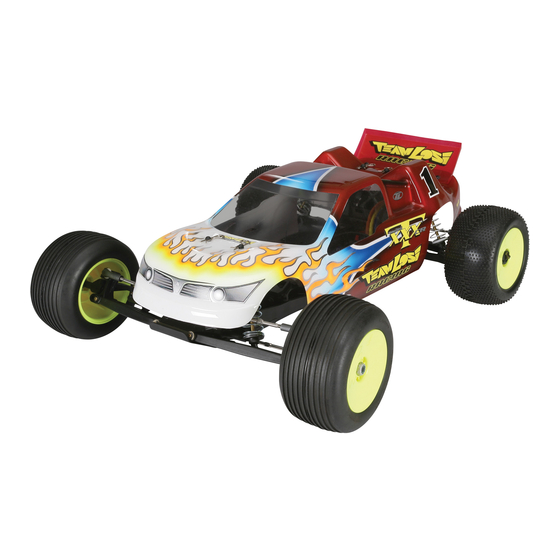
Summary of Contents for Team Losi XXX-T CR
- Page 2 Welcome Team Losi XXX-T CR Owner! Thank you for selecting the XXX-T CR as your new racing truck. The XXX-T CR has already distinguished itself as a top caliber racing chassis and as you will see, we have made every effort to produce a kit that is not only the most competitive but also easy to build and main- tain. The simple bag-by-bag assembly sequence and easily followed instructions and drawings combined with Team Losi’s world famous quality fitting parts will make building the XXX-T CR a most enjoyable project. Before you open the first bag, or start assembly, please take a moment to read through the following instructions. This will familiarize you with the various parts, assembly tips, and descriptions as well as the tools needed. Taking an extra moment before starting can save a good deal of time and assure proper assembly.
- Page 3 1 2. Filled-out XXX-T CR Kit Setup Sheet ....26 Team Losi is continually changing and improving designs; therefore, the actual part may appear slightly different than the illustrated part. Illustrations of parts and assemblies may be slightly distorted to enhance pertinent details.
- Page 4 BAG A STEP A-01 STEP A-02 Steering Assembly Kickplate Assembly Tighten the 6-40 x 5/16” Nut all the way A6206 A1610 A6081 down and then loosen it 2 full turns. SOLID 4-40 x 3/8” L 6-40 x 5/16” 3/32” x .930” A1620 Spring Cap A6306 A1610 A4159 Steering Brace Servo Saver Spring A6912...
- Page 5 BAG A STEP A-04 Front Bulkhead Assembly A6306 A6300 L 4-40 x 3/16” L 4-40 x 1/4” A4123 Body Mount A1109 Shock Tower, Front A6220 4-40” x 1/2” A6027 Std. 3/8” A6216 A6206 A6215 4-40” x 7/8” 4-40” x 3/8” Ball Stud A4159 Front Bulkhead STEP A-05 Front Clip Assembly...
- Page 6 STEP A-06 Tierod Assembly and Installation Use the Team Losi flat wrench to hold the Turnbuckle while installing the Ball Cups. • Be sure to install the assembled Tierod onto the truck with the groove (next to the center square section) on the driver’s left side for •...
-
Page 7: Servo Installation
BAG B STEP B-01 Servo Assembly Mount Servo Servo Manufacturer, Make/Model Position Horn All (DZ9000T/S DOES NOT FIT) 94357Z, 94358Z, 94649Z, 94360Z, 94452Z, 94758Z, 94737Z, 94738Z 94102Z, 94112Z All (S9102 DOES NOT FIT) A1620 Servo Mount PDS-2123, 2344, 2363, 2365, 2366 Table 2: Servo assembly and installation. - Page 8 BAG B STEP B-03 Chassis Assembly Steering Link (1.374in) A6010 Ball Cup, Short (34.9mm) A6265 Threaded Insert • The Steering Link length will vary de- pending on the brand and model of Servo used. This length is only a starting point and will most likely need to be adjusted in Step F-01. STEP B-04 Completed Chassis...
- Page 9 BAG C STEP C-01 Dogbone Assembly A3029 Cross Bone A3161 Coupler A3028 Quick Change Axle A3161 SOLID A6943 1/16” x 3/8” 10 x 15mm STEP C-02 Rear Hub Carrier Assembly A3029 A6026 Cross Bone A3028 Rear Axle Std. 1/4” A6215 Ball Stud A2122 Rear Hub A6945 8x14x4mm...
- Page 10 BAG C STEP C-03 Rear Suspension Assembly A6100 A6350 1/8” E-Clip 1/8 x .020” A4126 Rear Pivot A5050 A4138 1/8” x 1/16” Rear Hinge Pin Brace A2139 Rear Arm VLA A6092 SOLID 1/8” x 1.900” A6088 SOLID 1/8” x 1.246” STEP C-04 STEP C-05 Rear Bulkhead Assembly...
- Page 11 STEP C-06 Tierod Assembly and Installation Use the Team Losi flat wrench to hold the Turnbuckle while installing the Ball Cups. • Be sure to install the assembled Tierod onto the car with the groove (next to the center square section) •...
- Page 12 BAG D STEP D-01 Differential Assembly Apply a small amount of Clear Diff Grease to • A6951 both Diff Outdrives and the Diff Ring Shims Diff Balls, Carbide before installing the Diff Rings. A3036 Apply enough Clear Diff Grease to the top side •...
- Page 13 BAG D STEP D-03 Slipper Clutch Installation A6229 4-40 x 3/8” A4151 Fan Mount A3132 Slipper Plate A3123 A4123 Slipper Pad Motor Guard A3983 Spur Gear, 82T A3124 Spring Spacer A3125 Slipper Spring A3135 Spring Retaining Washer A6305 L 4-40 x 1/4” STEP D-04 Motor Installation •...
- Page 14 BAG D STEP D-05 Transmission Installation A6215 Ball Stud A3034 4-40 x 1-1/2” A6220 CAUTION! Ensure the Dogbone is 4-40 x 1/2” inserted into the slot in the Outdrive before installing the Transmission. STEP D-06 Completed Rear Clip Assembly...
- Page 15 BAG E STEP E-01 Shock Assembly Match short front Shock Bodies with assembled short front Shock Shafts and long rear Shock Bodies to assembled long rear Shock • Shafts. Holding the shock body inverted, fill the Shock Body with Shock Oil up to the bottom of the threads inside the Shock Body. •...
- Page 16 BAG E STEP E-02 STEP E-03 Front Shock Installation Rear Shock Installation A5013 Long Shock Bushing A6308 L 4-40 x 1/4” A5013 Short Shock Bushing A6308 L 4-40 x 1/4” A6204 A6204 4-40” x 1/2” 4-40” x 1/2” STEP E-04 Completed Front and Rear Clips...


Need help?
Do you have a question about the XXX-T CR and is the answer not in the manual?
Questions and answers