Table of Contents
Advertisement
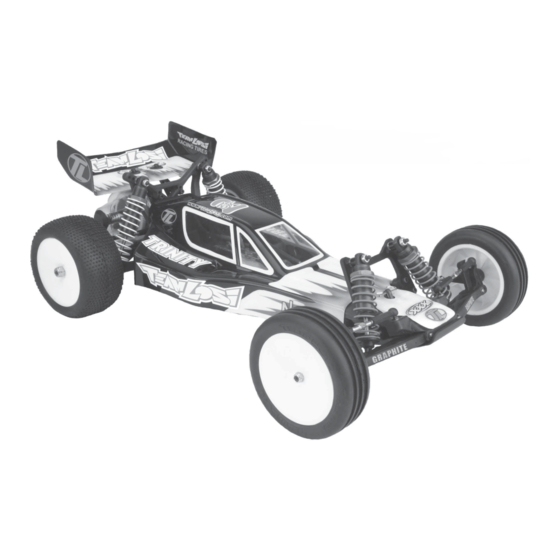
1/10 Scale 2wd Electric Off-Road Racing Buggy
BK2 OWNER'S MANUAL
Carefully read through all instructions to familiarize yourself with the parts, construction
technique, and tuning tips outlined in this manual. Being able to grasp the overall design of
your new XXX-BK2 racing buggy before begining the construction process will ensure a
smooth assembly.
Take your time and pay close attention to detail. Keep this manual for future reference.
Team Losi, A Division of Horizon Hobby inc.,
4710 East Guasti Rd., Ontario CA 91761
Phone: (909) 390-9595 / Fax: (909) 390-5356
P/N - 800-0214
(web) www.TeamLosi.com / (email) feedback@TeamLosi.com
J.A.C. - M.D.B.
MADE IN THE UNITED STATES OF AMERICA
11/01/2003
Advertisement
Table of Contents

Related Manuals for Team Losi BK2


Summary of Contents for Team Losi BK2
- Page 1 Carefully read through all instructions to familiarize yourself with the parts, construction technique, and tuning tips outlined in this manual. Being able to grasp the overall design of your new XXX-BK2 racing buggy before begining the construction process will ensure a smooth assembly.
- Page 2 When all else fails, read the instructions. For the latest setup tips and information on your new XXX-BK2, visit Team Losi on the Internet at: www.TeamLosi.com...
-
Page 3: Introduction
Before you start building your new XXX-BK2, I suggest you read through the instructions first. Be sure to check out the perfor- mance tips as you build and the tuning tips at the back of this manual as well. I hope you enjoy your XXX-BK2 as much as I do mine. -
Page 4: Table Of Contents
MOTORS AND GEARING The XXX-BK2 includes an 78-tooth, 48-pitch Kevlar spur gear. The overall internal drive ratio of the transmission is 2.56:1. The pinion gear that is used will determine the final drive ratio. To calculate the final drive ratio, first divide the spur gear size by the pinion gear size. For example, if you are using a 21-tooth pinion gear, you would divide 78 (spur gear size) by 21 (pinion gear size) 78/21=3.71. -
Page 5: Bag A
Figure 2. Thread a 3/16" Ball Stud through the Arms, into each Nut, and tighten. Once assembly of your new XXX-BK2 is complete, you may notice that the tires toe-in slightly as the suspension compresses. We have found this setting to yield the best performance. Should... - Page 6 BAG A (Continued) Steering Install: Step A-4 1. Insert a 3/32" x 3/16" Ball Bearing (13) into the two large, angled holes in the bottom of the front Kickplate (14). Insert the other two Bearings into the two outer holes in the Steering Brace (15). 2.
-
Page 7: Bag B
BAG B Step B-1 Front Bulkhead Install: There is a short Thread-Cutting Screw included in the Wrench bag. This Screw can be used to tap threads into the middle bottom hole in the front Bulkhead. Pre-tapping this hole makes it easier to install the Screw during assembly. - Page 8 BAG B (Continued) Front Spindle Assembly: Step B-4 *NOTE: If the 3/16" x 3/8" Bearing only has one Teflon seal ™ (colored, woven-looking) in it, position the bearing so that the seal faces the outside of the Spindle. 1. Insert a 3/16" x 3/8" sealed Bearing (27) into each side of both front Spindles [left (28), right (29)].
- Page 9 Brace. Secure the Brace by installing a 1/8" E-clip to the front of each Hinge Pin. The XXX-BK2 has been designed with Varaible Length Arms (VLA). For a more detailed description of the VLA system, please read the VLA section in the back of this manual.
- Page 10 BAG B (Continued) Front Suspension Arm Install: Step B-8 1. Hold the Chassis assembly upside down. Place the front Pivot Block (39) over the front edge of the front Kick plate (14) as shown in Figure 14. The front edge of the front Bulkhead (20) should be posi- tioned between the front Pivot Block and the Hinge Pin Brace (42).
- Page 11 BAG B (Continued) Steering Tierod: Step B-11 Figure 17A There is a small container/package of White Grease in this bag. It is recommended that this be applied to the threads of the Turn- buckles before trying to thread on the plastic Rod Ends. *NOTE: The two ends of the turnbuckle are threaded opposite.
-
Page 12: Bag C
BAG C Step C-1 CVD Dogbone Assembly: 1. Apply a thin coat of White Thrust Bearing/Assembly Grease (87) to the outside of the CVD Coupling (60). Insert the greased Cou- pling into the large hole in the rear Axle (62) so that the hole in the Coupling can be seen through the slots in the Axle. - Page 13 BAG C (Continued) Rear Hub Assembly Install: Step C-3 1. Place the left rear Hub (66) between the outer rails of the left rear suspension Arm (51) (Marked "L"). Be sure that the Ball Stud (22) is pointed towards the front of the Arm. Position a rear Hub Spacer (70) between the Hub and the Suspension Arm on each side of the Hub.
- Page 14 BAG C (Continued) Step C-5 Rear Shock Tower Assembly: 1. Insert two 4-40 x 7/8" Cap Head Screws (23), one on each side, through the second hole out on the top of the rear Shock Tower (55) as shown in Figure 23. Secure the Screws to the Shock Tower by threading a 4-40 Nut (25) onto each Screw and tightening.
- Page 15 BAG C (Continued) Rear Camber Tierod Assembly: Step C-7 Figure 25A There is a small container/package of White Grease in Bag B. It is recommended that this be applied to the threads of the Turnbuckles before trying to thread on the plastic Rod Ends. *NOTE: The two ends of the turnbuckle are threaded opposite.
-
Page 16: Bag D
BAG D Diff Nut Assembly: Step D-1 1. Locate the 5/64" Allen Wrench (74) supplied with the kit. Place the Diff Nut (73), over the Allen Wrench, with the ears on the Diff Nut towards the bent end of the Allen Wrench. 2. - Page 17 BAG D (Continued) Step D-4 Diff Gear: 1. Insert a 5mm x 8mm Ball Bearing (80) into the center of the Diff Gear (81). GREASE BOTH 2. Press a 3/32" carbide Diff Ball (82) into each of the 12 small holes SIDES in the Diff Gear.
- Page 18 BAG D (Continued) Bearing Insert to Female Outdrive: Step D-6 *NOTE: Be very careful when installing the foam Thrust Bear- ing Seals, do not over-stretch them. 1. Locate the Diff Adjusting Screw (84) and carefully stretch the two blue foam Thrust Bearing Seals (85) into the groves on the head of the Diff Screw.
- Page 19 BAG D (Continued) Diff Ring to Female Outdrive: Step D-8 1. Insert a 5mm x 8mm Ball Bearing (80) into the center of the SMALL AMOUNT female Outdrive/Diff Half (83). OF GREASE 2. Place the 1/16" Allen Wrench (92) through the slot in the Outdrive/ Diff Half containing the Diff Screw (84).
- Page 20 BAG D (Continued) Step D-10 Bearing to Left Gearbox Half: 1. Insert a 3/16" x 3/8" sealed Bearing (27) into the top Bearing seat of the left Gearbox Half (94). 2. Insert a 1/2" x 3/4" Bearing (95) into the lower Bearing seat of the left Gearbox Half.
-
Page 21: Gearbox Assembly
BAG D (Continued) Right Gearbox Half Assembly: Step D-12 *NOTE: Be sure there is no flashing left on the Top Shaft Spacer before you install it into the transimssion. 1. Slide the Top Shaft Spacer (99) over the long side of the Top Shaft (90). -
Page 22: Slipper Clutch Assembly
BAG D (Continued) Step D-14 Slipper Clutch Assembly: 1. Slide the Slipper Backing Plate (104) over the Top Shaft (90), aligning the flat sections on the Top Shaft (90) with the flat sections of the Slipper Backing Plate. 2. Place the Slipper Pad (105) on one side of the 78 tooth Spur Gear (106) and align the notches on the Spur Gear with the notches on the Slipper Pad. - Page 23 BAG D (Continued) Step D-15 Gearbox Install: 1. Place the assembled Chassis (19) on a flat table so that the rear suspension Arms (50), (51) and Chassis (19) are laying flat on the table. This will make installing the Gearbox a little easier. 2.
-
Page 24: Bag E
BAG E Shock Cartridge Assembly: Step E-1 *NOTE: THIS STEP WILL ONLY BE USED FOR CAR- TRIDGE MAINTENANCE , ALL CARTRIDGES IN THIS KIT HAVE BEEN PRE-ASSEMBLED AT THE FACTORY. 1. Place one Shock O-ring (113) into the Cartridge Body (114), making sure that the O-ring sits flat in the bottom of the Cartridge Body. - Page 25 BAG E (Continued) Step E-3 Shock End Install: 1. Using needle-nose pliers, or small vise grips, grasp the front Shock Shaft (118) between the grooves and thread a Shock End (120) onto the Shock Shaft. Thread the Shock End all the way onto the Shaft until the threads stop.
- Page 26 BAG E (Continued) Step E-5 Shock Oil Install: 1. Match the short, front Shock Bodies (125) to the short, front Shock Shafts (118), and the long, rear Shock Bodies (126) to the long, rear Shock Shafts (119). 2. Fill the Shock Bodies with Shock Fluid (127) up to the bottom of the threads inside the Shock Body.
- Page 27 BAG E (Continued) Step E-8 Rear Shock Install: 1.Position your car so that the Shock mounting holes in the front of the Arms are accessible. Make sure that the CVD Dogbones (59) stay in the Outdrives/ Diff halves (77)(83). 2. Position the bottom of an assembled rear Shock in front of the Shock mounting area on the left rear suspension Arm (51).
-
Page 28: Bag F
Team Losi Tire Glue (A-7880 "Thick", A-7881 "Thin") is the best Glue available for gluing R/C car Tires. This Glue was produced specifically for this purpose. The Team Losi (A-7884) off-road Tire Gluing kit is also available to get the job done right. It includes a bottle of glue, an applicator tube, and a ten rubber bands. -
Page 29: Bag G
BAG G Step G-1 Motor and Gear Cover Install: 1. Attach the motor (not included) to the Motor Plate (96) using two 3mm x 8mm Cap Head Screws (141) and two #4 Washers (58). Do not tighten the Screws yet. 2. - Page 30 BAG G (Continued) MOUNTING POST REQUIRED STEERING LINK SERVO TYPE PIN LOCATION SERVO ARM LENGTH AIRTRONICS Futaba S131, S131SH, S148, S3001, S5101, S9101,S9201, S9301, S9401, S9403 Futaba S3401, S9402, S9404, S9450 Futaba S9303 HiTech HS-605, HS-615, HS-925, HS-945 HiTech All other's Figure 55 NES-507, NES-513, NES-517, NES-901, NES-4000, NES-4131, NES-4721,...
- Page 31 BAG G (Continued) Step G-4 Servo Mounting: 1. Install the Servo into the Chassis (19) as shown in Figure 57. Insert the pin on the left Servo Mounting Post (146) into the hole in the Chassis. Move the Servo and Posts slightly until both the left and right Posts are inserted in the holes in the Chassis.
- Page 32 BAG G (Continued) Step G-7 Rear Body Mount Install: Figure 60A 1. Insert a 4-40 x 3/8" Flat Head Screw (54) into each of the two rear Body Mounts (151) from the side with the recess for the head of the Screw.
- Page 33 BAG G (Continued) Step G-9 Receiver Install: 1. Cut a piece of Two Sided Tape (156) to the same size as the bottom of the receiver (not included). Peel one side of the backing off and stick the Tape to the bottom of the receiver. 2.
- Page 34 BAG G (Continued) Painting the Body and Wing BODY AND WING PAINTING Prepare the Lexan Body and Wing for painting by washing them thoroughly (inside and out) with warm water and liquid detergent. Dry both the Body and Wing with a clean, soft cloth. Use the Window Masks (162) supplied to cover the windows from the inside. A high-quality masking tape should be used on the inside of the Body to mask off any stripes, panels, or designs that you wish to paint on the Body or Wing.
-
Page 35: Checklist Before Your First Run
BEFORE RUNNING YOUR NEW XXX-BK2 for the first time, you should run down the following checklist in order and complete the listed tasks. I'm sure you're anxious to get out and run your new XXX-BK2 now that it's built, but following this simple checklist will help to make your first run with your new car much more enjoyable. - Page 36 Washers Under the Front Camber Link Ball Stud can be added or removed. This is one of the most important adjustments on the XXX-BK2 car. You should get a feel for how the number of washers affects the handling. Adding washers will make the car more stable and keep the front end flatter.
- Page 37 XXX-BK2. A longer front camber link will usually make the car feel stiffer. This will help keep the car flatter with less roll, but can make the car handle worse in bumpy conditions. A shorter front camber link will result in more front end roll. This will increase high-speed steering and make the car better in bumps.
-
Page 38: Spare Parts List
SPARE PARTS LIST KEY # KIT/PART DESCRIPTION PART NO. SPARE PARTS DESCRIPTION SERVO SAVER BOTTOM A-1620 Steering/Servo Mount Assembly (Molded) SERVO SAVER POST A-1610 Steering Hardware Set SERVO SAVER TOP A-1620 Steering/Servo Mount Assembly (Molded) SERVO SAVER SPRING A-1610 Steering Hardware Set O-RING, ALUMINUM SHOCK NUT A-5049 Aluminum Shock Adjusting Nut (4) - Page 39 SPARE PARTS LIST KEY # KIT/PART DESCRIPTION PART NO. SPARE PARTS DESCRIPTION #4 WASHER A-6350 #4 and 1/8" Hardened Washers CVD DOGBONE A-9985 MIP CVD Rebuild Kit (1) CVD COUPLING A-9933 MIP CVD Rebuild Kit CVD COUPLING PIN A-9933 MIP CVD Rebuild Kit CVD AXLE A-9986 MIP CVD Rear Axle, (.200 Offset)
- Page 40 .6" Threaded Shock Body Set w/Nuts SHOCK BODY, REAR A-5055 .9" Threaded Shock Body Set w/Nuts SHOCK FLUID A-5224 Team Losi Certified Shock Fluid 30wt SHOCK SPRING CUP A-5079 Shock Ends & Cups (2) FRONT SHOCK SPRING A-5129 2" Spring 2.9 Rate (Orange)
Need help?
Do you have a question about the BK2 and is the answer not in the manual?
Questions and answers