Advertisement
Quick Links
Advertisement

Related Manuals for Asus P5LD2


Summary of Contents for Asus P5LD2
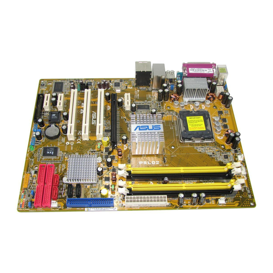
- Page 1 P5LD2...
- Page 2 T2028 © 2005...
- Page 6 ® ® ® ®...
- Page 7 • • • • • • • • • • • •...
- Page 8 • • • • •...
- Page 9 Jumper Free Jumper Mode (Default) P5LD2-TAYZ 10839 11036 11XX11XX11...
- Page 10 ® ® ® ® ® ®...
- Page 16 ® ® ® ® ® ® ® ® ® ® ®...
- Page 17 ®...
- Page 23 SB_PWR ® Standby Powered P5LD2 Onboard LED Power...
- Page 24 ®...
- Page 25 23cm (9in) KBPWR PS/2KBMS T: Mouse CHA_FAN2 CPU_FAN B: Keyboard ATX12V SPDIF_O1 SPDIF_O2 COM1 LGA775 USBPW34 USB12 USBPW12 LAN_USB34 Top: Back surround L/R Center: Intel Side surround L/R Below: Bass 945P Top:Line In Center:Line Out Below:Mic In PCIEX1_1 Marvell 88E8053 PCIEX16 PCI1 ®...
- Page 28 ® ® • • • ® P5LD2 CPU Socket 775...
- Page 31 ® ® ® ® • ® ® ® • •...
- Page 32 CPU_FAN ® P5LD2 CPU fan connector 2-10...
- Page 33 2-11...
- Page 34 2-12...
- Page 35 ® P5LD2 DIMM sockets • • • • 2-13...
- Page 36 2-14...
- Page 37 2-15...
- Page 38 2-16...
- Page 39 • • 2-17...
- Page 40 2-18...
- Page 41 2-19...
- Page 42 2-20...
- Page 43 CLRTC ® Normal Clear CMOS P5LD2 Clear RTC RAM (Default) 2-21...
- Page 44 USBPW34 USBPW12 +5VSB (Default) USBPW56 USBPW78 ® +5VSB P5LD2 USB device wake-up (Default) KBPWR +5VSB (Default) ® P5LD2 Keyboard power setting 2-22...
- Page 45 2-23...
- Page 46 2-24...
- Page 47 FLOPPY PIN 1 P5LD2 Floppy disk drive connector SEC_EIDE PIN 1 PRI_EIDE PIN 1 P5LD2 RAID connectors 2-25...
- Page 48 • • PRI_IDE P5LD2 IDE connector PIN 1 2-26...
- Page 49 SATA4 SATA3 ® SATA1 SATA2 P5LD2 SATA connectors • • 2-27...
- Page 50 Right Audio Channel ® Ground Ground Left Audio Channel P5LD2 CD audio connector AAFP ® AC ‘97 audio pin definition P5LD2 Analog front panel connector • • 2-28...
- Page 51 ® USB56 USB78 P5LD2 USB 2.0 connectors ® GAME P5LD2 Game connector 2-29...
- Page 52 CPU_FAN PWR_FAN PWR_FAN +12V CPU_FAN Rotation CHA_FAN2 CHA_FAN1 CHA_FAN2 ® +12V Rotation CHA_FAN1 P5LD2 Fan connectors ® CHASSIS (Default) P5LD2 Chassis intrusion connector 2-30...
- Page 53 +12 Volts +5 Volts +5V Standby +5 Volts Power OK -5 Volts Ground Ground ® +5 Volts Ground Ground Ground +5 Volts PSON# Ground Ground +3 Volts -12 Volts P5LD2 ATX power connectors +3 Volts +3 Volts • • • 2-31...
- Page 54 SPEAKER PLED PANEL ® RESET IDE_LED PWRSW P5LD2 System panel connector Requires an ATX power supply. • • • • • 2-32...
- Page 58 ® ® ® ®...
- Page 62 • • A:\>afudos /oOLDBIOS1.rom A:\>afudos /oOLDBIOS1.rom AMI Firmware Update Utility - Version 1.19 (ASUS V2.07(03.11.24BB)) Copyright (C) 2002 American Megatrends, Inc. All rights reserved. Reading flash ..done Write to file ..ok A:\>...
- Page 63 A:\>afudos /iP5LD2.rom A:\>afudos /iP5LD2.ROM AMI Firmware Update Utility - Version 1.19 (ASUS V2.07(03.11.24BB)) Copyright (C) 2002 American Megatrends, Inc. All rights reserved. WARNING!! Do not turn off power during flash BIOS Reading file ..done Reading flash ..done Advance Check ..
- Page 64 A:\>afudos /iP5LD2.ROM AMI Firmware Update Utility - Version 1.10 Copyright (C) 2002 American Megatrends, Inc. All rights reserved. WARNING!! Do not turn off power during flash BIOS Reading file ..done Reading flash ..done Advance Check ..Erasing flash ..done Writing flash ..
- Page 65 Bad BIOS checksum. Starting BIOS recovery... Checking for floppy... Bad BIOS checksum. Starting BIOS recovery... Checking for floppy... Floppy found! Reading file “P5LD2.ROM”. Completed. Start flashing...
- Page 66 Bad BIOS checksum. Starting BIOS recovery... Checking for floppy... Bad BIOS checksum. Starting BIOS recovery... Checking for floppy... Floppy not found! Checking for CD-ROM... CD-ROM found. Reading file “P5LD2.ROM”. Completed. Start flashing...
- Page 67 EZFlash starting BIOS update Checking for floppy... EZFlash starting BIOS update Checking for floppy... Floppy found! Reading file “P5LD2.ROM”. Completed. Start erasing..| Start Programming...| Flashed successfully. Rebooting. • •...
- Page 70 4-10...
- Page 71 4-11...
- Page 72 Legacy Diskette A [1.44M, 3.5 in] Use [+] or [-] to Primary IDE Master [ST320413A] Primary IDE Slave [ASUS CD-S520/A] configure system time. Third IDE Master [Not Detected] Third IDE Slave [Not Detected] Fourth IDE Master [Not Detected]...
- Page 73 Language [English] Use [+] or [-] to Primary IDE Master :[ST320413A] configure system time. Primary IDE Slave :[ASUS CD-S340] Secondary IDE Master :[Not Detected] Secondary IDE Slave :[Not Detected] Third IDE Master :[Not Detected] Fourth IDE Master...
- Page 74 Legacy Diskette A [1.44M, 3.5 in] Primary IDE Master [ST320413A] Use [+] or [-] to Primary IDE Slave [ASUS CD-S520/A] configure system time. Third IDE Master [Not Detected] Third IDE Slave [Not Detected] Fourth IDE Master [Not Detected]...
- Page 75 Primary IDE Master Select the type Device : Hard Disk of device connected Vendor : ST320413A to the system. Size : 20.0GB LBA Mode : Supported Block Mode : 16 Sectors PIO Mode Async DMA : MultiWord DMA-2 Ultra DMA : Ultra DMA-5 SMART Monitoring: Supported Type...
- Page 76 IDE Configuration When in AHCI/RAID mode SATA Configure SATA As [Standard IDE] controller is Onboard IDE Operate Mode [Enhanced Mode] forced to Native Enhanced Mode Support On [S-ATA] mode. IDE Detect Time Out (Sec) [35] ® 4-16...
- Page 77 4-17...
- Page 78 AMIBIOS Version : 0106 Build Date : 04/15/05 Processor Type : Genuine Intel(R) CPU 3.20GHz Speed : 3200 MHz Count System Memory Total : 1024MB Appropriated : 0MB Select Screen Available : 1024MB Select Item Change Option General Help Save and Exit Exit 4-18...
- Page 79 JumperFree Configuration Adjust system LAN Cable Status frequency/voltage. USB Configuration CPU Configuration Chipset Onboard Devices Configuration PCIPnP Configure System Frequency/Voltage Select the targe CPU frequency, and the AI Overclocking [Auto] relevant parameters will be auto-adjusted. Frequencies higher than CPU manufacturer recommends are not guaranteed to be stable.
- Page 80 FSB 1066 266 MHz FSB 800 200 MHz FSB 533 133 MHz 4-20...
- Page 81 4-21...
- Page 82 4-22...
- Page 83 POST Check LAN Cable [Disabled] Check LAN cable during POST. LAN Cable Status Pair Status Length Normal Normal Normal Normal 4-23...
- Page 84 USB Configuration Enables USB host controllers. Module Version - 2.23.2-9.4 USB Devices Enabled: None USB Function [Enabled] Legacy USB Support [Auto] USB 2.0 Controller [Enabled] USB 2.0 Controller Mode [HiSpeed] BIOS EHCI Hand-Off [Disabled] 4-24...
- Page 85 Configure Advanced CPU settings Sets the ratio between CPU Core Manufacturer: Intel Clock and the FSB Brand String: Genuine Intel(R) CPU 3.20GHz Frequency. Frequency : 3200 MHz NOTE: If an invalid FSB Speed : 800 MHz ratio is set in CMOS Cache L1 : 16 KB then actual and...
- Page 86 4-26...
- Page 87 Advanced Chipset Settings Enable or disable DRAM timing. Configure DRAM Timing by SPD [Enabled] Hyper Path 3 [Auto] Booting Graphic Adapter Priori [PCI Express/PCI] PEG Buffer Length [Auto] Link Latency [Auto] PEG Root Control [Auto] PEG Link Mode [Auto] Slot Power [Auto] High Priority Port Select [Disabled]...
- Page 88 4-28...
- Page 89 Configure Win627EHF Super IO Chipset Enable or disable High Definition Audio HD Audio Controller [Enabled] Controller. Front Panel Support Type [HD Audio] Onboard PCIEX GbE LAN [Enabled] LAN Option ROM [Disabled] ITE8211F Controller [IDE Mode] Detecting Device Time [Quick Mode] Serial Port1 Address [3F8/IRQ4] Parallel Port Address...
- Page 90 ® 4-30...
- Page 91 Advanced PCI/PnP Settings NO: Lets the BIOS configue all the WARNING: Setting wrong values in below sections devices in the system. may cause system to malfunction. YES: Lets the Plug And Play O/S [No] operating system PCI Latency Timer [64] configure Plug and Allocate IRQ to PCI VGA [Yes]...
- Page 92 4-32...
- Page 93 Suspend Mode [Auto] Select the ACPI state Repost Video on S3 Resume [No] used for System ACPI 2.0 Support [No] Suspend. ACPI APIC Support [Enabled] APM Configuration Hardware Monitor 4-33...
- Page 94 APM Configuration Go into On/Off or Suspend when Power Power Button Mode [On/Off] button is pressed. Restore on AC Power Loss [Power Off] Power On By RTC Alarm [Disabled] Power On By External Modems [Disabled] Power On By PCI Devices [Disabled] Power On By PCIE Devices [Disabled]...
- Page 95 4-35...
- Page 96 Hardware Monitor AI Quiet [Disabled] CPU Q-Fan Control [Disabled] CPU Temperature [32.5ºC/90.5ºF] MB Temperature [36.0ºC/96.5ºF] CPU Fan Speed (RPM) [3813RPM] Chassis Fan1 Speed (RPM) [N/A] Chassis Fan2 Speed (RPM) [N/A] Power Fan Speed (RPM) [N/A] VCORE Voltage [ 1.320V] 3.3V Voltage [ 3.345V] 5V Voltage [ 5.094V]...
- Page 97 4-37...
- Page 98 Enter Go to Sub-screen General Help Save and Exit Exit Boot Device Priority 1st Boot Device [1st FLOPPY DRIVE] 2nd Boot Device [PM-ST330620A] 3rd Boot Device [PS-ASUS CD-S360] Select Screen Select Item Enter Go to Sub-screen General Help Save and Exit Exit 4-38...
- Page 99 Allows BIOS to skip Boot Settings Configuration certain tests while Quick Boot [Enabled] booting. This will Full Screen Logo [Enabled] decrease the time AddOn ROM Display Mode [Force BIOS] needed to boot the Bootup Num-Lock [On] system. PS/2 Mouse Support [Auto] Wait For ‘F1’...
- Page 100 Security Settings <Enter> to change password. Supervisor Password : Not Installed <Enter> again to User Password : Not Installed disabled password. Change Supervisor Password Select Screen Select Item Change Option General Help Save and Exit Exit 4-40...
- Page 101 Security Settings Supervisor Password : Not Installed User Password : Not Installed Change Supervisor Password User Access Level [Full Access] Change User Password Clear User Password Password Check [Setup] Select Screen Select Item Change Option General Help Save and Exit Exit 4-41...
- Page 102 4-42...
- Page 103 Exit Options Exit system setup Exit & Save Changes after saving the Exit & Discard Changes changes. Discard Changes F10 key can be used Load Setup Defaults for this operation. Select Screen Select Item Enter Go to Sub-screen General Help Save and Exit Exit 4-43...
- Page 104 4-44...
- Page 108 ®...
- Page 116 5-10...
- Page 117 • • • • 5-11...
- Page 118 ® 5-12...
- Page 119 5-13...
- Page 120 5-14...
- Page 121 5-15...
- Page 122 5-16...
- Page 123 ® ® ® ® 5-17...
- Page 124 ® 5-18...
- Page 125 Intel(R) Matrix Storage Manager Option ROM v5.0.0.1032 ICH7R wRAID5 Copyright(C) 2003-05 Intel Corporation. All Rights Reserved. MAIN MENU 1. Create RAID Volume 2. Delete RAID Volume 3. Reset Disks to Non-RAID 4. Exit DISK/VOLUME INFORMATION RAID Volumes: None defined. Physical Disks: Port Drive Model Serial # Size...
-
Page 126: Raid0(Stripe)
Intel(R) Matrix Storage Manager Option ROM v5.0.0.1032 ICH7R wRAID5 Copyright(C) 2003-05 Intel Corporation. All Rights Reserved. CREATE ARRAY MENU Name: Volume0 RAID Level: RAID0(Stripe) Disks: Select Disks Strip Size: 128KB Capacity: Create Volume DISK/VOLUME INFORMATION Enter a string between 1 and 16 characters in length that can be used to uniquely identify the RAID volume. - Page 127 • • • WARNING: ALL DATA ON SELECTED DISKS WILL BE LOST. Are you sure you want to create this volume? (Y/N): 5-21...
-
Page 128: Raid1(Mirror)
Intel(R) Matrix Storage Manager Option ROM v5.0.0.1032 ICH7R wRAID5 Copyright(C) 2003-05 Intel Corporation. All Rights Reserved. CREATE ARRAY MENU Name: Volume1 RAID Level: RAID1(Mirror) Disks: Select Disks Strip Size: Capacity: XX.X Create Volume DISK/VOLUME INFORMATION Enter a string between 1 and 16 characters in length that can be used to uniquely identify the RAID volume. - Page 129 Intel(R) Matrix Storage Manager Option ROM v5.0.0.1032 ICH7R wRAID5 Copyright(C) 2003-05 Intel Corporation. All Rights Reserved. CREATE ARRAY MENU Name: Volume10 RAID Level: RAID10(RAID0+1) Disks: Select Disks Strip Size: 128KB Capacity: XXX.X GB Create Volume DISK/VOLUME INFORMATION Enter a string between 1 and 16 characters in length that can be used to uniquely identify the RAID volume.
-
Page 130: Raid5(Parity)
WARNING: ALL DATA ON SELECTED DISKS WILL BE LOST. Are you sure you want to create this volume? (Y/N): Intel(R) Matrix Storage Manager Option ROM v5.0.0.1032 ICH7R wRAID5 Copyright(C) 2003-05 Intel Corporation. All Rights Reserved. CREATE ARRAY MENU Name: Volume5 RAID Level: RAID5(Parity) Disks:... - Page 131 SELECT DISKS Port Drive Model Serial # Size Status 0 XXXXXXXXXXXX XXXXXXXX XX.XGB Non-RAID Disk 1 XXXXXXXXXXXX XXXXXXXX XX.XGB Non-RAID Disk 2 XXXXXXXXXXXX XXXXXXXX XX.XGB Non-RAID Disk 3 XXXXXXXXXXXX XXXXXXXX XX.XGB Non-RAID Disk Select 2 to 4 disks to use in creating the volume. [↑...
- Page 132 Intel(R) Matrix Storage Manager Option ROM v5.0.0.1032 ICH7R wRAID5 Copyright(C) 2003-05 Intel Corporation. All Rights Reserved. DELETE VOLUME MENU Name Level Drives Capacity Status Bootable Volume0 RAIDX(xxxxx) XXX.XGB Normal HELP Deleting a volume will destroy the volume data on the drive(s) and cause any member disks to become available as non-RAID disks.
-
Page 133: Reset Raid Data
RESET RAID DATA Resetting RAID data will remove internal RAID structures from the selected RAID disks. By removing these structures, the drive will revert back to a non-RAID disk. WARNING: Resetting a disk causes all data on the disk to be lost. Port Drive Model Serial # Size Status... - Page 134 RESET RAID DATA Resetting RAID data will remove the internal RAID structures from the selected RAID disks. By removing these structures the drive will revert back to a Non-RAID disk. WARNING: Resetting a disk causes all data on the disk to be lost. Port Drive Model Serial # Size...
- Page 135 Loading FreeDOS FAT KERNEL GO! Press any key to boot from CDROM... 1) Make ICH7 32-bit RAID driver disk 2) Make ICH7 64-bit RAID driver disk 3) Format floppy disk 4) FreeDOS command prompt Please choose 1 ~ 4 Insert new diskette for drive B:\ and press ENTER when ready...
- Page 136 • • • 5-30...
- Page 138 ® ® ®...
- Page 139 ® ® ® ® ® ® ® ® ® ® ® ® ®...
- Page 141 ® ® ® ® ® ® ® ®...
Need help?
Do you have a question about the P5LD2 and is the answer not in the manual?
Questions and answers