Table of Contents
Advertisement
Quick Links
Advertisement
Table of Contents

Subscribe to Our Youtube Channel
Related Manuals for Asus P5LD2-VM SE


Summary of Contents for Asus P5LD2-VM SE
- Page 1 P5LD2-VM SE...
- Page 2 Product warranty or service will not be extended if: (1) the product is repaired, modified or altered, unless such repair, modification of alteration is authorized in writing by ASUS; or (2) the serial number of the product is defaced or missing.
-
Page 3: Table Of Contents
Contents Notices ....................vi Safety information ................vii About this guide ................viii Typography ..................ix P5LD2-VM SE specifications summary ..........x Chapter 1: Product introduction Chapter 1: Product introduction Chapter 1: Product introduction Chapter 1: Product introduction Chapter 1: Product introduction Welcome! ................ - Page 4 Creating a bootable floppy disk ......2-2 2.1.2 ASUS EZ Flash utility ..........2-3 2.1.3 AFUDOS utility ............2-4 2.1.4 ASUS CrashFree BIOS 2 utility ........ 2-6 2.1.5 ASUS Update utility ..........2-8 BIOS setup program ............2-11 2.2.1 BIOS menu screen ..........2-12 2.2.2...
- Page 5 Installing an operating system ..........3-2 Support CD information ............3-2 3.2.1 Running the support CD ......... 3-2 3.2.2 Drivers menu ............3-3 3.2.3 Utilities menu ............3-4 3.2.4 Manuals menu ............3-5 3.2.5 ASUS Contact information ........3-6 v v v v v...
-
Page 6: Notices
Notices Federal Communications Commission Statement Federal Communications Commission Statement Federal Communications Commission Statement Federal Communications Commission Statement Federal Communications Commission Statement This device complies with Part 15 of the FCC Rules. Operation is subject to the following two conditions: • This device may not cause harmful interference, and •... -
Page 7: Safety Information
Safety information Electrical safety Electrical safety Electrical safety Electrical safety Electrical safety • To prevent electrical shock hazard, disconnect the power cable from the electrical outlet before relocating the system. • When adding or removing devices to or from the system, ensure that the power cables for the devices are unplugged before the signal cables are connected. -
Page 8: About This Guide
A S U S w e b s i t e s A S U S w e b s i t e s The ASUS website provides updated information on ASUS hardware and software products. Refer to the ASUS contact information. -
Page 9: Typography
Conventions used in this guide Conventions used in this guide Conventions used in this guide Conventions used in this guide Conventions used in this guide To make sure that you perform certain tasks properly, take note of the following symbols used throughout this manual. D A N G E R / W A R N I N G : D A N G E R / W A R N I N G : D A N G E R / W A R N I N G :... -
Page 10: P5Ld2-Vm Se Specifications Summary
P5LD2-VM SE specifications summary C P U C P U C P U LGA775 socket for Intel ® Core™2 Extreme/Core™2 Duo/ C P U C P U Pentium ® D/Pentium ® 4/Celeron ® D processors Compatible with Intel ® 05B/05A/06B processors Supports Intel ®... - Page 11 B I O S f e a t u r e s 4 Mb Flash ROM, AMI BIOS, PnP, WfM2.0, DMI2.0, SM BIOS 2.3, ASUS EZ Flash, CrashFree BIOS2, C.P.R. (CPU Parameter Recall) S p e c i a l f e a t u r e s...
- Page 12 x i i x i i x i i x i i x i i...
- Page 13 This chapter describes the motherboard features and the new technologies it supports. Product introduction A S U S P 5 L D 2 - V M S E A S U S P 5 L D 2 - V M S E 1 - 1 1 - 1 A S U S P 5 L D 2 - V M S E...
-
Page 14: Welcome
P 5 L D 2 - V M S E m o t h e r b o a r d ! The motherboard delivers a host of new features and latest technologies, making it another standout in the long line of ASUS quality motherboards! Before you start installing the motherboard, and hardware devices on it, check the items in your package with the list below. - Page 15 Intel Intel Intel Intel Intel ® ® ® ® ® Core™2 Processor Ready Core™2 Processor Ready Core™2 Processor Ready Core™2 Processor Ready Core™2 Processor Ready This motherboard supports the latest Intel ® Core™2 processor in the LGA775 package. With the new Intel ®...
- Page 16 AI Overclocking AI Overclocking AI Overclocking AI Overclocking AI Overclocking This feature allows convenient overclocking up to 30 percent (depending on the installed CPU and DRAM) to enhance system performance while still maintaining system stability. See section “2.4.1 JumperFree Configuration” to set the BIOS items for overclocking.
-
Page 17: Innovative Asus Features
ASUS EZ Flash BIOS ASUS EZ Flash BIOS With the ASUS EZ Flash, you can easily update the system BIOS even before loading the operating system. No need to use a DOS-based utility or boot from a floppy disk. See page 2-3 for details. -
Page 18: Before You Proceed
LED. SB_PWR Standby Powered P5LD2-VM SE Onboard LED Power 1 - 6 1 - 6 C h a p t e r 1 : P r o d u c t i n t r o d u c t i o n... -
Page 19: Motherboard Overview
Motherboard overview Before you install the motherboard, study the configuration of your chassis to ensure that the motherboard fits into it. Make sure to unplug the power cord before installing or removing the motherboard. Failure to do so can cause you physical injury and damage motherboard components. -
Page 20: Motherboard Layout
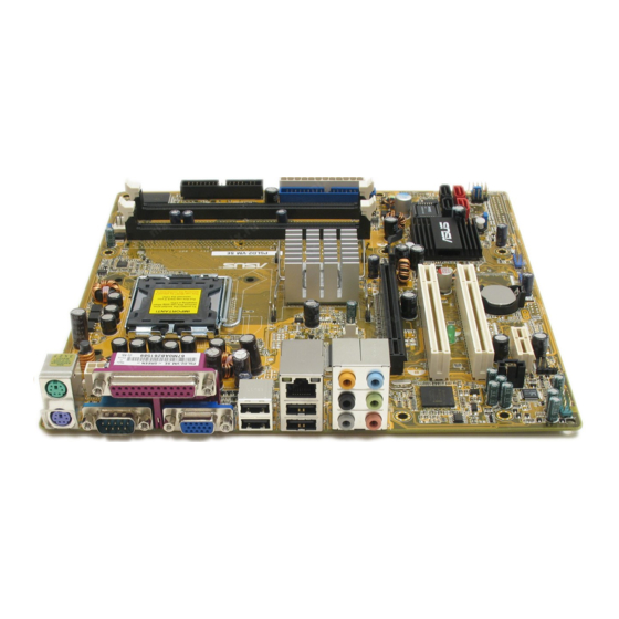
1.5.3 1.5.3 Motherboard layout Motherboard layout 1.5.3 1.5.3 1.5.3 Motherboard layout Motherboard layout Motherboard layout CPU_FAN PS/2KBMS T: Mouse B: Keyboard COM1 ATX12V LGA775 VGA1 F_USB12 LAN_USB34 ® Intel Top:Rear Speaker Out GMCH Center: Side Speaker Out 945G Below: Center/Subwoofer Top:Line In Center:Line Out CHA_FAN... -
Page 21: Central Processing Unit (Cpu)
Contact your retailer immediately if the PnP cap is missing, or if you see any damage to the PnP cap/socket pins/motherboard components. ASUS will shoulder the cost of repair only if the damage is shipment/ transit-related. •... - Page 22 Press the load lever with your thumb (A) and move it to the left (B) until it is released from the retention tab. P n P C a p P n P C a p P n P C a p P n P C a p P n P C a p R e t e n t i o n t a b...
- Page 23 Close the load plate (A), then push the load lever (B) until it snaps into the retention tab. The CPU fits in only one correct orientation. DO NOT force the CPU into the socket to prevent bending the connectors on the socket and damaging the CPU! The motherboard supports Intel ®...
-
Page 24: Installling The Cpu Heatsink And Fan
1.6.2 1.6.2 1.6.2 1.6.2 1.6.2 Installling the CPU heatsink and fan Installling the CPU heatsink and fan Installling the CPU heatsink and fan Installling the CPU heatsink and fan Installling the CPU heatsink and fan The Intel ® Pentium ® 4 LGA775 processor requires a specially designed heatsink and fan assembly to ensure optimum thermal condition and performance. - Page 25 CPU FAN PWM CPU FAN IN CPU FAN PWR P5LD2-VM SE CPU fan connector Do not forget to connect the CPU fan connector! Hardware monitoring errors can occur if you fail to plug this connector. A S U S P 5 L D 2 - V M S E...
-
Page 26: Uninstalling The Cpu Heatsink And Fan
1.6.3 1.6.3 1.6.3 1.6.3 1.6.3 Uninstalling the CPU heatsink and fan Uninstalling the CPU heatsink and fan Uninstalling the CPU heatsink and fan Uninstalling the CPU heatsink and fan Uninstalling the CPU heatsink and fan To uninstall the CPU heatsink and fan: Disconnect the CPU fan cable from the connector on the motherboard. - Page 27 Remove the heatsink and fan assembly from the motherboard. Rotate each fastener clockwise to reset the orientation. N a r r o w e n d o f t h e g r o o v e N a r r o w e n d o f t h e g r o o v e N a r r o w e n d o f t h e g r o o v e N a r r o w e n d o f t h e g r o o v e N a r r o w e n d o f t h e g r o o v e...
-
Page 28: System Memory
DDR DIMM socket. The figure illustrates the location of the DDR2 DIMM sockets: P5LD2-VM SE 240-pin DDR2 DIMM sockets C h a n n e l C h a n n e l... -
Page 29: Ddr2 Qualified Vendors List
DDR2 Qualified Vendors List The following table lists the memory modules that have been tested and qualified for use with this motherboard. Visit the ASUS website (www.asus.com) for the latest DDR2 DIMM modules for this motherboard. DDR2 533 Qualified Vendors List... -
Page 30: Installing A Dimm
1.7.4 1.7.4 1.7.4 Installing a DIMM Installing a DIMM Installing a DIMM 1.7.4 1.7.4 Installing a DIMM Installing a DIMM Unplug the power supply before adding or removing DIMMs or other system components. Failure to do so can cause severe damage to both the motherboard and the components. -
Page 31: Expansion Slots
Expansion slots In the future, you may need to install expansion cards. The following sub-sections describe the slots and the expansion cards that they support. Make sure to unplug the power cord before adding or removing expansion cards. Failure to do so may cause you physical injury and damage motherboard components. -
Page 32: Interrupt Assignments
1.8.3 1.8.3 Interrupt assignments Interrupt assignments 1.8.3 1.8.3 1.8.3 Interrupt assignments Interrupt assignments Interrupt assignments Standard interrupt assignments Standard interrupt assignments Standard interrupt assignments Standard interrupt assignments Standard interrupt assignments I R Q I R Q S t a n d a r d F u n c t i o n S t a n d a r d F u n c t i o n I R Q I R Q... -
Page 33: Pci Slots
1.8.4 1.8.4 PCI slots PCI slots 1.8.5 1.8.5 PCI Express x16 PCI Express x16 1.8.4 1.8.4 1.8.4 PCI slots PCI slots PCI slots 1.8.5 1.8.5 1.8.5 PCI Express x16 PCI Express x16 PCI Express x16 The PCI slots support cards such as This motherboard supports one PCI a LAN card, SCSI card, USB card, Express x16 graphics card. -
Page 34: Jumpers
Removing the cap will cause system boot failure! CLRTC Normal Clear CMOS P5LD2-VM SE Clear RTC RAM (Default) You do not need to clear the RTC when the system hangs due to overclocking. For system failure due to overclocking, use the C.P.R. (CPU Parameter Recall) feature. -
Page 35: 1.10 Connectors
1.10 Connectors 1.10.1 1.10.1 1.10.1 1.10.1 1.10.1 Rear panel connectors Rear panel connectors Rear panel connectors Rear panel connectors Rear panel connectors 1 . 1 . P S / 2 m o u s e p o r t ( g r e e n ) . P S / 2 m o u s e p o r t ( g r e e n ) . - Page 36 8 . 8 . M i c r o p h o n e p o r t ( p i n k ) . M i c r o p h o n e p o r t ( p i n k ) . M i c r o p h o n e p o r t ( p i n k ) .
-
Page 37: Internal Connectors
PIN 1. PIN 1 P5LD2-VM SE Floppy disk drive connector 2 . 2 . P r i m a r y I D E c o n n e c t o r ( 4 0 - 1 p i n P R I _ I D E ) - Page 38 The speaker allows you to hear system beeps and warnings. SPEAKER Speak Out P5LD2-VM SE Speaker out connector 1 - 2 6 1 - 2 6 C h a p t e r 1 : P r o d u c t i n t r o d u c t i o n...
- Page 39 CPU FAN PWR CHA_FAN +12V Rotation P5LD2-VM SE Fan connectors A S U S P 5 L D 2 - V M S E A S U S P 5 L D 2 - V M S E 1 - 2 7...
- Page 40 Connect one end of the S/PDIF audio cable to this connector and the other end to the S/PDIF module. SPDIF_OUT P5LD2-VM SE Digital audio connector The S/PDIF out module is purchased separately. 7 . 7 . P o w e r L E D c o n n e c t o r ( 3 - p i n P L E D )
-
Page 41: Atx Power Connectors
Ground Ground +3 Volts -12 Volts P5LD2-VM SE ATX power connectors +3 Volts +3 Volts A S U S P 5 L D 2 - V M S E A S U S P 5 L D 2 - V M S E... - Page 42 Right Audio Channel Ground Ground Left Audio Channel P5LD2-VM SE CD audio connector Enable the CD-IN function in the audio utility when using this connector. 1 0 . 1 0 . 1 0 . U S B c o n n e c t o r s ( 1 0 - 1 p i n U S B 5 6 , U S B 7 8 )
-
Page 43: Chassis Intrusion Connector
AAFP Azalia Legacy AC’97 compliant definition compliant definition P5LD2-VM SE Analog front panel connector It is recommended that you connect a high-definition front panel audio module to this connector to avail of the motherboard’s high-definition audio capability. 1 2 . - Page 44 IDE LED PWR_LED+ IDE_LED+ Requires an ATX power supply. P5LD2-VM SE System panel connector The sytem panel connector is color-coded for easy connection. Refer to the connector description below for details. • P o w e r / S o f t - o f f b u t t o n ( B l a c k 2 - p i n P W R S W )
- Page 45 This chapter tells how to change the system settings through the BIOS Setup menus. Detailed descriptions of the BIOS parameters are also provided. BIOS setup A S U S P 5 L D 2 - V M S E A S U S P 5 L D 2 - V M S E 2 - 1 2 - 1 A S U S P 5 L D 2 - V M S E...
-
Page 46: Managing And Updating Your Bios
Refer to the corresponding sections for details on these utilities. Save a copy of the original motherboard BIOS file to a bootable floppy disk in case you need to restore the BIOS in the future. Copy the original motherboard BIOS using the ASUS Update or AFUDOS utilities. 2.1.1 2.1.1 2.1.1... -
Page 47: Asus Ez Flash Utility
ASUS EZ Flash utility ASUS EZ Flash utility The ASUS EZ Flash feature allows you to update the BIOS without having to go through the long process of booting from a floppy disk and using a DOS-based utility. The EZ Flash utility is built-in the BIOS chip so it is accessible by pressing <Alt>... -
Page 48: Afudos Utility
2.1.3 2.1.3 2.1.3 2.1.3 2.1.3 AFUDOS utility AFUDOS utility AFUDOS utility AFUDOS utility AFUDOS utility The AFUDOS utility allows you to update the BIOS file in DOS environment using a bootable floppy disk with the updated BIOS file. This utility also allows you to copy the current BIOS file that you can use as backup when the BIOS fails or gets corrupted during the updating process. - Page 49 Updating the BIOS file To update the BIOS file using the AFUDOS utility: Visit the ASUS website (www.asus.com) and download the latest BIOS file for the motherboard. Save the BIOS file to a bootable floppy disk. Write the BIOS filename on a piece of paper. You need to type the exact BIOS filename at the DOS prompt.
-
Page 50: Asus Crashfree Bios 2 Utility
ASUS CrashFree BIOS 2 utility ASUS CrashFree BIOS 2 utility The ASUS CrashFree BIOS 2 is an auto recovery tool that allows you to restore the BIOS file when it fails or gets corrupted during the updating process. You can update a corrupted BIOS file using the motherboard support CD or the floppy disk that contains the updated BIOS file. - Page 51 Restart the system after the utility completes the updating process. The recovered BIOS may not be the latest BIOS version for this motherboard. Visit the ASUS website (www.asus.com) to download the latest BIOS file. A S U S P 5 L D 2 - V M S E...
-
Page 52: Asus Update Utility
ASUS Update utility ASUS Update utility ASUS Update utility ASUS Update utility The ASUS Update is a utility that allows you to manage, save, and update the motherboard BIOS in Windows ® environment. The ASUS Update utility allows you to: •... - Page 53 Updating the BIOS through the Internet Updating the BIOS through the Internet Updating the BIOS through the Internet To update the BIOS through the Internet: Launch the ASUS Update utility from the Windows ® desktop by clicking S t a r t S t a r t >...
- Page 54 A S U S U p d a t e A S U S U p d a t e. The ASUS Update main window appears. U p d a t e B I O S f r o m a...
-
Page 55: Bios Setup Program
• Visit the ASUS website (www.asus.com) to download the latest BIOS file for this motherboard and . A S U S P 5 L D 2 - V M S E... -
Page 56: Bios Menu Screen
2.2.1 2.2.1 2.2.1 BIOS menu screen BIOS menu screen BIOS menu screen 2.2.1 2.2.1 BIOS menu screen BIOS menu screen M e n u i t e m s M e n u i t e m s M e n u b a r M e n u b a r C o n f i g u r a t i o n f i e l d s C o n f i g u r a t i o n f i e l d s... -
Page 57: Menu Items
For example, selecting M a i n M a i n M a i n shows the Primary IDE Master :[ST320413A] configure system time. Primary IDE Slave :[ASUS CD-S340] Secondary IDE Master :[Not Detected] Secondary IDE Slave :[Not Detected] Main menu items. Third IDE Master... -
Page 58: Main Menu
Main menu When you enter the BIOS Setup program, the Main menu screen appears, giving you an overview of the basic system information. Refer to section “2.2.1 BIOS menu screen” for information on the menu screen items and how to navigate through them. Use [ENTER], [TAB] System Time [11:51:19]... -
Page 59: Primary, Third And Fourth Ide Master/Slave
2.3.4 2.3.4 2.3.4 Primary, Third and Fourth IDE Master/Slave Primary, Third and Fourth IDE Master/Slave Primary, Third and Fourth IDE Master/Slave 2.3.4 2.3.4 Primary, Third and Fourth IDE Master/Slave Primary, Third and Fourth IDE Master/Slave While entering Setup, the BIOS automatically detects the presence of IDE devices. -
Page 60: Ide Configuration
PIO Mode [Auto] PIO Mode [Auto] PIO Mode [Auto] PIO Mode [Auto] PIO Mode [Auto] Selects the PIO mode. Configuration options: [Auto] [0] [1] [2] [3] [4] DMA Mode [Auto] DMA Mode [Auto] DMA Mode [Auto] DMA Mode [Auto] DMA Mode [Auto] Selects the DMA mode. - Page 61 Enhanced Mode Support On [S-ATA] The default setting S-ATA allows you to use native OS on Serial ATA and Parallel ATA ports. We recommend that you do not change the default setting for better OS compatibility. In this setting, you may use legacy OS on the Parallel ATA ports o n l y i f o n l y i f o n l y i f...
-
Page 62: System Information
2.3.6 2.3.6 System Information System Information 2.3.6 2.3.6 2.3.6 System Information System Information System Information This menu gives you an overview of the general system specifications. The BIOS automatically detects the items in this menu. AMIBIOS Version : 0128 Build Date : 05/11/05 Processor Type : Genuine Intel(R) CPU 3.20GHz... -
Page 63: Advanced Menu
Advanced menu The Advanced menu items allow you to change the settings for the CPU and other system devices. Take caution when changing the settings of the Advanced menu items. Incorrect field values can cause the system to malfunction. Configure CPU. JumperFree Configuration USB Configuration CPU Configuration... - Page 64 The following item appears only when you set the A I O v e r c l o c k i n g A I O v e r c l o c k i n g A I O v e r c l o c k i n g A I O v e r c l o c k i n g A I O v e r c l o c k i n g item to [Manual].
- Page 65 CPU VCore Voltage [Auto] CPU VCore Voltage [Auto] CPU VCore Voltage [Auto] CPU VCore Voltage [Auto] CPU VCore Voltage [Auto] Sets the operating VCore voltage. Configuration options: [Auto] [1.7000V] [1.6875V] [1.6750V] [1.6625V] [1.6500V] [1.6375V] [1.6250V] [1.6125V] [1.6000V] [1.5875V] [1.5750V] [1.5625V] [1.5500V] [1.5375V] [1.5250V] [1.5125V] [1.5000V] [1.4875V] [1.4750V] [1.4625V] [1.4500V] [1.4375V] [1.4250V] [1.4125V] [1.4000V] [1.3875V] [1.3750V] [1.3625V] [1.3500V] [1.3375V]...
-
Page 66: Usb Configuration
2.4.2 2.4.2 USB Configuration USB Configuration 2.4.2 2.4.2 2.4.2 USB Configuration USB Configuration USB Configuration The items in this menu allows you to change the USB-related features. Select an item then press <Enter> to display the configuration options. USB Configuration Module Version - 2.23.0-F.4 USB Devices Enabled: None USB Function... -
Page 67: Cpu Configuration
2.4.3 2.4.3 CPU Configuration CPU Configuration 2.4.3 2.4.3 2.4.3 CPU Configuration CPU Configuration CPU Configuration The items in this menu show the CPU-related information that the BIOS automatically detects. Configure Advanced CPU settings Sets the ratio between CPU Core Clock and the Manufacturer: Intel FSB Frequency. - Page 68 Execute Disable Function [Disabled] Execute Disable Function [Disabled] Execute Disable Function [Disabled] Execute Disable Function [Disabled] Execute Disable Function [Disabled] Enables or disables the Execute Disable function. This item appears only when you install a processor with the Execute Disable function. Configuration options: [Disabled] [Enabled] Enhanced C1 Control [Auto] Enhanced C1 Control [Auto]...
-
Page 69: Chipset
2.4.4 2.4.4 Chipset Chipset 2.4.4 2.4.4 2.4.4 Chipset Chipset Chipset The Chipset menu allows you to change the advanced chipset settings. Select an item then press <Enter> to display the sub-menu. Advanced Chipset Settings Configure DRAM Timing by SPD [Enabled] Booting Graphic Adapter Priori [PCI Express/Int-VG] Internal Graphics Mode Select [Enabled, 8MB]... -
Page 70: Onboard Devices Configuration
Booting Graphic Adapter Priority [PCI Express/Int-VGA] Booting Graphic Adapter Priority [PCI Express/Int-VGA] Booting Graphic Adapter Priority [PCI Express/Int-VGA] Booting Graphic Adapter Priority [PCI Express/Int-VGA] Booting Graphic Adapter Priority [PCI Express/Int-VGA] Allows selection of the graphics controller to use as primary boot device. Configuration options: [Internal VGA] [PCI Express/Int-VGA] [PCI Express/PCI] [PCI/PCI Express] [PCI/Int-VGA] Internal Graphics Mode Select [Enabled, 8MB]... - Page 71 Serial Port1 Address [3F8/IRQ4] Serial Port1 Address [3F8/IRQ4] Serial Port1 Address [3F8/IRQ4] Serial Port1 Address [3F8/IRQ4] Serial Port1 Address [3F8/IRQ4] Allows you to select the Serial Port1 base address. Configuration options: [Disabled] [3F8/IRQ4] [2F8/IRQ3] [3E8/IRQ4] [2E8/IRQ3] Parallel Port Address [378] Parallel Port Address [378] Parallel Port Address [378] Parallel Port Address [378]...
-
Page 72: Pci Pnp
2.4.6 2.4.6 2.4.6 2.4.6 2.4.6 PCI PnP PCI PnP PCI PnP PCI PnP PCI PnP The PCI PnP menu items allow you to change the advanced settings for PCI/PnP devices. The menu includes setting IRQ and DMA channel resources for either PCI/PnP or legacy ISA devices, and setting the memory size block for legacy ISA devices. -
Page 73: Power Menu
IRQ-xx assigned to [PCI Device] IRQ-xx assigned to [PCI Device] IRQ-xx assigned to [PCI Device] IRQ-xx assigned to [PCI Device] IRQ-xx assigned to [PCI Device] When set to [PCI Device], the specific IRQ is free for use of PCI/PnP devices. When set to [Reserved], the IRQ is reserved for legacy ISA devices. -
Page 74: Apm Configuration
2.5.4 2.5.4 2.5.4 2.5.4 2.5.4 APM Configuration APM Configuration APM Configuration APM Configuration APM Configuration APM Configuration Enabled or disable APM. Power Button Mode [On/Off] Restore on AC Power Loss [Power Off] Power On By RTC Alarm [Disabled] Power On By External Modems [Disabled] Power On By PCI Devices [Disabled]... - Page 75 Power On By PCI Devices [Disabled] Power On By PCI Devices [Disabled] Power On By PCI Devices [Disabled] Power On By PCI Devices [Disabled] Power On By PCI Devices [Disabled] When set to [Enabled], this parameter allows you to turn on the system through a PCI LAN or modem card.
-
Page 76: Hardware Monitor
CPU Q-Fan Control [Disabled] CPU Q-Fan Control [Disabled] CPU Q-Fan Control [Disabled] Allows you to enable or disable the ASUS Q-Fan feature that smartly adjusts the fan speeds for more efficient system operation. Configuration options: [Disabled] [Enabled] The C P U F A N P R O F I L E M O D E... - Page 77 Chassis Fan Speed [xxxxRPM] or [N/A] Chassis Fan Speed [xxxxRPM] or [N/A] Chassis Fan Speed [xxxxRPM] or [N/A] Chassis Fan Speed [xxxxRPM] or [N/A] Chassis Fan Speed [xxxxRPM] or [N/A] The onboard hardware monitor automatically detects and displays the chassis fan speed in rotations per minute (RPM). If the fan is not connected to the chassis, the specific field shows N/A.
-
Page 78: Boot Menu
[1st FLOPPY DRIVE] 2nd Boot Device [PM-ST330620A] 3rd Boot Device [PS-ASUS CD-S360] 1st ~ xxth Boot Device [1st Floppy Drive] 1st ~ xxth Boot Device [1st Floppy Drive] 1st ~ xxth Boot Device [1st Floppy Drive] 1st ~ xxth Boot Device [1st Floppy Drive]... -
Page 79: Boot Settings Configuration
This allows you to enable or disable the full screen logo display feature. Configuration options: [Disabled] [Enabled] Set this item to [Enabled] to use the ASUS MyLogo™ feature. Add On ROM Display Mode [Force BIOS] Add On ROM Display Mode [Force BIOS]... -
Page 80: Security
Interrupt 19 Capture [Disabled] Interrupt 19 Capture [Disabled] Interrupt 19 Capture [Disabled] Interrupt 19 Capture [Disabled] Interrupt 19 Capture [Disabled] When set to [Enabled], this function allows the option ROMs to trap Interrupt 19. Configuration options: [Disabled] [Enabled] 2.6.3 2.6.3 2.6.3 2.6.3 2.6.3... - Page 81 After you have set a supervisor password, the other items appear to allow you to change other security settings. Security Settings Supervisor Password : Not Installed User Password : Not Installed Change Supervisor Password User Access Level [Full Access] Change User Password Clear User Password Password Check [Setup]...
-
Page 82: Exit Menu
Password Check [Setup] Password Check [Setup] Password Check [Setup] Password Check [Setup] Password Check [Setup] When set to [Setup], BIOS checks for user password when accessing the Setup utility. When set to [Always], BIOS checks for user password both when accessing Setup and booting the system. Configuration options: [Setup] [Always] Exit menu The Exit menu items allow you to load the optimal or failsafe default values... - Page 83 Exit & Discard Changes Exit & Discard Changes Exit & Discard Changes Exit & Discard Changes Exit & Discard Changes Select this option only if you do not want to save the changes that you made to the Setup program. If you made changes to fields other than System Date, System Time, and Password, the BIOS asks for a confirmation before exiting.
- Page 84 2 - 4 0 2 - 4 0 C h a p t e r 2 : B I O S s e t u p C h a p t e r 2 : B I O S s e t u p 2 - 4 0 2 - 4 0 2 - 4 0...
- Page 85 This chapter describes the contents of the support CD that comes with the motherboard package. Software support A S U S P 5 L D 2 - V M S E A S U S P 5 L D 2 - V M S E 3 - 1 3 - 1 A S U S P 5 L D 2 - V M S E...
-
Page 86: Installing An Operating System
The contents of the support CD are subject to change at any time without notice. Visit the ASUS website(www.asus.com) for updates. 3.2.1 3.2.1 Running the support CD Running the support CD 3.2.1... -
Page 87: Drivers Menu
3.2.2 3.2.2 Drivers menu Drivers menu 3.2.2 3.2.2 3.2.2 Drivers menu Drivers menu Drivers menu The drivers menu shows the available device drivers if the system detects installed devices. Install the necessary drivers to activate the devices. QFE Update QFE Update QFE Update QFE Update QFE Update... -
Page 88: Utilities Menu
ASUS Update ASUS Update ASUS Update ASUS Update The ASUS Update utility allows you to update the motherboard BIOS in a Windows ® environment. This utility requires an Internet connection either through a network or an Internet Service Provider (ISP). See page 2-8 for details. -
Page 89: Manuals Menu
ADOBE Acrobat Reader V7.0 ADOBE Acrobat Reader V7.0 ADOBE Acrobat Reader V7.0 ADOBE Acrobat Reader V7.0 ADOBE Acrobat Reader V7.0 Installs the Adobe ® Acrobat ® Reader V7.0. Microsoft DirectX 9.0c Microsoft DirectX 9.0c Microsoft DirectX 9.0c Microsoft DirectX 9.0c Microsoft DirectX 9.0c Installs the Microsoft ®... -
Page 90: Asus Contact Information
Click the C o n t a c t C o n t a c t C o n t a c t tab to display the ASUS contact information. You can also find this information on the inside front cover of this user guide.
Need help?
Do you have a question about the P5LD2-VM SE and is the answer not in the manual?
Questions and answers