Table of Contents
Advertisement
Quick Links
Advertisement
Table of Contents

Subscribe to Our Youtube Channel
Related Manuals for DFI 648FX-ALE


Summary of Contents for DFI 648FX-ALE
- Page 1 648FX-AL 648FX-ALE Rev. A+ System Board User’s Manual 73300323...
- Page 2 Copyright This publication contains information that is protected by copy- right. No part of it may be reproduced in any form or by any means or used to make any transformation/adaptation without the prior written permission from the copyright holders. This publication is provided for informational purposes only.
-
Page 3: Fcc And Doc Statement On Class B
Battery: • Danger of explosion if battery incorrectly replaced. • Replace only with the same or equivalent type recommend by the manufacturer. • Dispose of used batteries according to the batter y manufacturer’s instructions. Joystick or MIDI port: • Do not use any joystick or MIDI device that requires more than 10A current at 5V DC. -
Page 4: System Board
(Mainboard Utility CD) will appear. Click the “TOOLS” icon then click “Manual” on the main menu. System Board This user’s manual is for the 648FX-AL and 648FX-ALE system boards. The only difference between these boards is the 648FX- AL system board supports onboard IEEE 1394A. -
Page 5: Table Of Contents
Table of Contents Chapter 1 - Introduction 1.1 Features and Specifications................1.2 Hyper-Threading Technology Functionality Require- ments............................1.3 Package Checklist..................... Chapter 2 - Hardware Installation System Board Layout ..................System Memory......................CPU............................Jumper Settings......................Rear Panel I/O Ports..................... I/O Connectors......................Chapter 3 - BIOS Setup 3.1 Award BIOS Setup Utility.................. - Page 6 Introduction Appendix A - Enabling the Hyper-Threading T echnology A.1 Enabling the Hyper-Threading Technology........Appendix B - Using the Suspend to RAM Function B.1 Using the Suspend to RAM Function..........Appendix C - System Error Messages C.1 POST Beep........................C.2 Error Messages......................Appendix D - Troubleshooting D.1 Troubleshooting Checklist................
-
Page 7: Chapter 1 - Introduction
1.1 Features and Specifications 1.1.1 Features Chipset • 648FX-AL ® North bridge: SiS 648FX ® South bridge: SiS • 648FX-ALE ® North bridge: SiS 648FX ® South bridge: SiS 963L Processor The system board is equipped with Socket 478 for installing one of the following supported processors. - Page 8 Introduction Expansion Slots The system board is equipped with 1 AGP slot and 5 PCI slots. AGP (Accelerated Graphics Port) AGP is an interface designed to support high performance 3D graphics cards. It utilizes a dedicated pipeline to access system memory for texturing, z-buffering and alpha blending.
- Page 9 Introduction Onboard LAN Features • Uses Phy fast ethernet controller • Integrated IEEE 802.3, 10BASE-T and 100BASE-TX compatible • 32-bit PCI master interface • Integrated power management functions • Full duplex support at both 10 and 100 Mbps • Supports IEEE 802.3u auto-negotiation •...
- Page 10 Introduction USB Ports The system board supports USB 2.0 and USB 1.1 ports. USB 1.1 suppor ts 12Mb/second bandwidth while USB 2.0 suppor ts 480Mb/second bandwidth providing a marked improvement in device transfer speeds between your computer and a wide range of simultaneously accessible external Plug and Play peripherals.
- Page 11 Introduction I/O Connectors • 2 connectors for 4 additional external USB 2.0/1.1 ports • 3 connectors for 3 external IEEE 1394A ports (648FX-AL only) • 1 front audio connector for external line-out and mic-in jacks • 1 CD-in internal audio connector •...
- Page 12 Introduction Wake-On-LAN This feature allows the network to remotely wake up a Soft Power Down (Soft-Off) PC. It is supported via the onboard LAN port, via a PCI LAN card that uses the PCI PME (Power Manage- ment Event) signal or via a LAN card that uses the Wake-On- LAN connector.
- Page 13 Introduction ACPI STR The system board is designed to meet the ACPI (Advanced Con- figuration and Power Interface) specification. ACPI has energy sav- ing features that enables PCs to implement Power Management and Plug-and-Play with operating systems that support OS Direct ®...
-
Page 14: Hyper-Threading Technology Functionality Requirements
Introduction 1.2 Hyper-Threading Technology Functionality Requirements Enabling the functionality of Hyper-Threading Technology for your computer system requires ALL of the following platforms. Components: ® ® • CPU - an Intel Pentium 4 Processor with HT Technology ® • Chipset - an Intel chipset that supports HT Technology •... -
Page 15: Chapter 2 - Hardware Installation
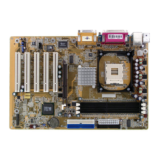
Hardware Installation Chapter 2 - Hardware Installation 2.1 System Board Layout CPU fan KB/Mouse DIMM LED +12V power USB 1-2 COM 1 power COM 2 Line-out Line-in 648FX Mic-in DDR 1 DDR 3 IrDA DDR 2 AGP Slot IDE 2 IDE 1 chip PCI Slot 1... -
Page 16: Hardware Installation
PCI Slot 3 CD-in Chassis fan Audio Codec PCI Slot 4 S/PDIF PCI Slot 5 SPEAKER RESET HD-LED Front audio SURR_CON ATX-SW PWR-LED 648FX-ALE Note: The illustrations on the following pages are based on the system board that supports onboard IEEE 1394A. -
Page 17: System Memory
Hardware Installation Warning: Electrostatic discharge (ESD) can damage your system board, processor, disk drives, add-in boards, and other components. Perform the upgrade instruction procedures described at an ESD workstation only. If such a station is not available, you can provide some ESD protection by wearing an antistatic wrist strap and attaching it to a metal part of the system chassis. -
Page 18: Installing The Dim Module
Hardware Installation 2.2.1 Installing the DIM Module A DIM module simply snaps into a DIMM socket on the system board. Pin 1 of the DIM module must correspond with Pin 1 of the socket. Notch Pin 1 1. Pull the “tabs” which are at the ends of the socket to the side. 2. -
Page 19: Cpu
Hardware Installation 2.3 CPU 2.3.1 Overview The system board is equipped with a surface mount 478-pin CPU socket. This socket is exclusively designed for installing an Intel processor. 2.3.2 Installing the CPU 1. Locate Socket 478 on the system board. 2. - Page 20 Hardware Installation 3. Position the CPU above the socket then align the gold mark on the corner of the CPU (designated as pin 1) with pin 1 of the socket. Important: Handle the CPU by its edges and avoid touching the pins. Gold mark Pin 1 4.
-
Page 21: Installing The Fan And Heat Sink
Hardware Installation 5. Once the CPU is in place, push down the lever to lock the socket. The lever should click on the side tab to indicate that the CPU is completely secured in the socket. 2.3.3 Installing the Fan and Heat Sink The CPU must be kept cool by using a CPU fan with heatsink. - Page 22 Hardware Installation 1. The system board comes with the retention module base already installed. Retention Retention hole hole Retention Retention hole hole Retention module base 2. Position the fan / heat sink and retention mechanism assembly on the CPU, then align and snap the retention legs’ hooks to the retention holes at the 4 corners of the retention module base.
- Page 23 Hardware Installation 3. The retention levers at this time remains unlocked as shown in the illustration below. Retention lever Retention lever 4. Move the retention levers to their opposite directions then push them down. This will secure the fan / heat sink and retention mechanism assembly to the retention module base.
-
Page 24: Jumper Settings
Hardware Installation 2.4 Jumper Settings 2.4.1 Jumper Settings for Clearing CMOS Data 1-2 On: Normal 2-3 On: (default) Clear CMOS Data If you encounter the following, a) CMOS data becomes corrupted. b) You forgot the keyboard, supervisor or user password. c) You are unable to boot-up the computer system because the processor’s ratio/clock was incorrectly set in the BIOS. - Page 25 Hardware Installation 4. After powering-on the system, press <Del> to enter the main menu of the BIOS. 5. Select the Frequency/Voltage Control submenu and press <Enter>. 6. Set the “CPU Clock Ratio” or “CPU Frequency” field to its default setting or an appropriate frequency ratio or bus clock. Refer to the Frequency/Voltage Control section in chapter 3 for more information.
-
Page 26: Rear Panel I/O Ports
Hardware Installation 2.5 Rear Panel I/O Ports RJ45 PS/2 Parallel GAME/MIDI Mouse PS/2 COM 1 COM 2 USB 1-2 Line- Line- Mic- The rear panel I/O ports consist of the following: • PS/2 mouse port • PS/2 keyboard port • LAN port •... - Page 27 Hardware Installation 2.5.1 PS/2 Mouse and PS/2 Keyboard Ports PS/2 Mouse PS/2 Keyboard The system board is equipped with an onboard PS/2 mouse (Green) and PS/2 keyboard (Purple) ports - both at location CN1 of the system board. The PS/2 mouse port uses IRQ12. If a mouse is not connected to this port, the system will reserve IRQ12 for other expansion cards.
-
Page 28: Rj45 Lan Port
Hardware Installation 2.5.2 RJ45 LAN Port RJ45 LAN The system board is equipped with an onboard RJ45 LAN port at location CN7 of the system board. It allows the system board to connect to a local area network by means of a network hub. BIOS Setting Enable or disable the onboard LAN in the Integrated Peripherals submenu (“SIS OnChip PCI Device”... -
Page 29: Universal Serial Bus Ports
Hardware Installation 2.5.3 Universal Serial Bus Ports USB 2 USB 1 10 9 10 9 Ground Ground Ground Ground +Data +Data +Data +Data USB 5-6 USB 3-4 -Data -Data -Data -Data Two onboard USB 2.0/1.1 ports (Black) are at locations CN7 of the system board. - Page 30 Hardware Installation Driver Installation You may need to install the proper drivers in your operating system to use the USB device. Refer to your operating system’s manual or documentation for more information. If you are using a USB 2.0 device, install the “SiS USB 2.0 Driv- ers”.
-
Page 31: Serial Ports
Hardware Installation 2.5.4 Serial Ports COM 1 COM 2 The system board is equipped with two onboard serial ports (COM 1: CN6 and COM 2: CN5) - both in Teal/Turquoise color. These ports are RS-232C asynchronous communication ports with 16C550A-compatible UARTs that can be used with modems, serial printers, remote display terminals, and other serial devices. -
Page 32: Parallel Port
Hardware Installation 2.5.5 Parallel Port Parallel The system board has a standard parallel port (Burgundy) at location CN9 for interfacing your PC to a parallel printer. It sup- ports SPP, ECP and EPP. Setting Function Allows normal speed operation but (Standard Parallel Port) in one direction only. - Page 33 Hardware Installation 2.5.6 Game Port Game Port The Game/MIDI port is identical to that of a standard PC game adapter or game I/O port. Connect an analog joystick to the 15- pin D-sub connector (Gold) at location CN8 of the system board.
- Page 34 Hardware Installation 2.5.7 Audio Line-out Mic-in Line-in Front audio SURR_CON Audio Jacks The system board is equipped with 3 audio jacks. A jack is a one- hole connecting interface for inserting a plug. • Line-out Jack (Lime - CN4) This jack is used to connect external speakers for audio output from the system board.
- Page 35 Hardware Installation • Line-in Jack (Light Blue - CN3) This jack can be connected to the line-out jack of any external audio devices such as Hi-fi set, CD player, AM/FM radio tuner, synthesizer, etc. Connect a stereo cable from the line-out jack of your external device to this line-in jack.
- Page 36 Hardware Installation aligned with pin 1 of J6. If you are not using this connector, re- place the jumper caps back to their original pin locations. Now install the card-edge bracket to the system chassis. Driver Installation Install the “Audio Drivers”. The 3D Audio Configuration software, which is an audio panel for setting basic audio configurations, will at the same time be installed into your system.
-
Page 37: I/O Connectors
Hardware Installation 2.6 I/O Connectors 2.6.1 CD-in Internal Audio Connector Ground Ground Right audio Left audio channel channel The CD-in (J5) connector is used to receive audio from a CD- ROM drive, TV tuner or MPEG card. - Page 38 Hardware Installation 2.6.2 S/PDIF Connector SPDIF out SPDIF in The system board is equipped with a S/PDIF connector. One card- edge bracket, mounted with S/PDIF ports, will be provided as an option. Install the card-edge bracket to the system chassis then connect the audio cable connector to J4.
-
Page 39: Floppy Disk Drive Connector
Hardware Installation 2.6.3 Floppy Disk Drive Connector The system board is equipped with a shrouded floppy disk drive connector that supports two standard floppy disk drives. To prevent improper floppy cable installation, the shrouded floppy disk header has a keying mechanism. The 34-pin connector on the floppy cable can be placed into the header only if pin 1 of the connector is aligned with pin 1 of the header. - Page 40 Hardware Installation 2.6.4 IEEE 1394A Connectors (648FX-AL only) 1394-1 1394-3 1394-2 The system board is equipped with three IEEE 1394A connec- tors: 1394-1 (J12), 1394-2 (J13) and 1394-3 (J17). One card-edge bracket, mounted with 1394A port(s), will be provided as an op- tion.
-
Page 41: Ide Disk Drive Connector
Hardware Installation 2.6.5 IDE Disk Drive Connector IDE 2 IDE 1 IDE 2 IDE 1 The system board is equipped with two shrouded PCI IDE headers that will interface four Enhanced IDE (Integrated Drive Electronics) disk drives. To prevent improper IDE cable installation, each shrouded PCI IDE header has a keying mechanism. - Page 42 Hardware Installation Note: Refer to your disk drive user’s manual for information about selecting proper drive switch settings. Adding a Second IDE Disk Drive When using two IDE drives, one must be set as the master and the other as the slave. Follow the instructions provided by the drive manufacturer for setting the jumpers and/or switches on the drives.
-
Page 43: Irda Connector
Hardware Installation 2.6.6 IrDA Connector IRRX Ground N. C. IRTX Connect your IrDA cable to connector J2 on the system board. Note: The sequence of the pin functions on some IrDA cable may be reversed from the pin function defined on the system board. Make sure to connect the cable to the IrDA connector according to their pin functions. -
Page 44: Cpu Fan Connector
Hardware Installation 2.6.7 CPU Fan Connector Power Ground N.C. The CPU must be kept cool by using a fan with heatsink. Connect the CPU fan to the 3-pin fan connector at location J15 of the system board. -
Page 45: Chassis Fan Connector
Hardware Installation 2.6.8 Chassis Fan Connector N. C. Power Ground The chassis fan connector (J21) is used to connect a cooling fan. The cooling fan will provide adequate airflow throughout the chassis to prevent overheating the CPU and system board com- ponents. - Page 46 Hardware Installation 2.6.9 Wake-On-LAN Connector Ground +5VSB Your LAN card package should include a cable. Connect one end of the cable to the wakeup header on the card and the other end to location J8 on the system board. The network will detect Magic Packet and assert a wakeup signal to power-up the system.
- Page 47 Hardware Installation 2.6.10 DIMM Standby Power LED DIMM Standby Power LED The DIMM Standby Power LED will turn red when the system’s power is on or when it is in the Suspend state (Power On Sus- pend or Suspend to RAM). It will not light when the system is in the Soft-Off state.
-
Page 48: Power Connectors
Hardware Installation 2.6.11 Power Connectors 3.3V 3.3V -12V 3.3V Ground Ground PS-ON Ground Ground Ground Ground Ground PW-OK 5VSB +12V +12V Ground Ground +12V We recommend that you use a power supply that complies with the ATX12V Power Supply Design Guide Version 1.1. An ATX12V power supply has a standard 20-pin ATX main power connector and a 4-pin +12V power connector that must be inserted onto CN11 and CN10 connectors respectively. -
Page 49: Front Panel Connectors
Hardware Installation 2.6.12 Front Panel Connectors RESET SPEAKER HD-LED PWR-LED ATX-SW HD-LED: Primary/Secondary IDE LED This LED will light when the hard drive is being accessed. RESET: Reset Switch This switch allows you to reboot without having to power off the system thus prolonging the life of the power supply or system. - Page 50 Hardware Installation PWR-LED: Power/Standby LED When the system’s power is on, this LED will light. When the system is in the S1 (POS - Power On Suspend) state, it will blink every second. When the system is in the S3 (STR - Suspend To RAM) state, it will blink every second.
-
Page 51: Chapter 3 - Bios Setup
BIOS Setup Chapter 3 - BIOS Setup 3.1 Award BIOS Setup Utility The Basic Input/Output System (BIOS) is a program that takes care of the basic level of communication between the processor and peripherals. In addition, the BIOS also contains codes for vari- ous advanced features found in this system board. -
Page 52: Bios Setup
BIOS Setup 3.1.1 Standard CMOS Features Use the arrow keys to highlight “Standard CMOS Features” and press <Enter>. The following screen will appear. The settings on the screen are for reference only. Your version may not be identical to this one. 3.1.1.1 Date The date format is <day>, <month>, <date>, <year>. - Page 53 BIOS Setup 3.1.1.3 IDE Primary Master, IDE Primary Slave, IDE Secondary Master and IDE Secondary Slave Move the cursor to the “IDE Primary Master”, “IDE Primary Slave”, “IDE Secondary Master” or “IDE Secondary Slave” field, then press <Enter>. The settings on the screen are for reference only. Your version may not be identical to this one.
- Page 54 BIOS Setup Capacity Displays the approximate capacity of the disk drive. Usually the size is slightly greater than the size of a formatted disk given by a disk checking program. Cylinder This field displays the number of cylinders. Head This field displays the number of read/write heads. Precomp This field displays the number of cylinders at which to change the write timing.
- Page 55 BIOS Setup 3.1.1.5 Video This field selects the type of video adapter used for the primary system monitor. Although secondary monitors are supported, you do not have to select the type. The default setting is EGA/VGA. EGA/VGA Enhanced Graphics Adapter/Video Graphics Array. For EGA, VGA, SVGA and PGA monitor adapters.
- Page 56 BIOS Setup 3.1.1.8 Extended Memory Displays the amount of extended memory detected during boot- 3.1.1.9 Total Memory Displays the total memory available in the system.
-
Page 57: Advanced Bios Features
BIOS Setup 3.1.2 Advanced BIOS Features The Advanced BIOS Features allows you to configure your sys- tem for basic operation. Some entries are defaults required by the system board, while others, if enabled, will improve the per- formance of your system or let you set some features according to your preference. - Page 58 BIOS Setup field. Also, disable this field if you are installing or running certain operating systems like Windows ® 98/2000/ME/XP or the operating system may not install nor work. 3.1.2.2 CPU L1 & L2 Cache These fields speed up the memory access. The default value is enabled.
- Page 59 BIOS Setup 3.1.2.7 Swap Floppy Drive When this field is enabled and the system is booting from the floppy drive, the system will boot from drive B instead of drive A. When this field is disabled and the system is booting from the floppy drive, the system will boot from drive A.
- Page 60 BIOS Setup the arrow keys. You can then select the typematic rate and typematic delay in the “Typematic Rate (Chars/Sec)” and “Typematic Delay (Msec)” fields below. 3.1.2.12 Typematic Rate (Chars/Sec) This field allows you to select the rate at which the keys are accelerated.
- Page 61 BIOS Setup 3.1.2.18 HDD S.M.A.R.T. Capability The system board supports SMART (Self-Monitoring, Analysis and Reporting Technology) hard drives. SMART is a reliability predic- tion technology for ATA/IDE and SCSI drives. The drive will pro- vide sufficient notice to the system or user to backup data prior to the drive’s failure.
-
Page 62: Advanced Chipset Features
BIOS Setup 3.1.3 Advanced Chipset Features The settings on the screen are for reference only. Your version may not be identical to this one. This section gives you functions to configure the system based on the specific features of the chipset. The chipset manages bus speeds and access to system memory resources. - Page 63 BIOS Setup 3.1.3.1 DRAM Clock/Timing Control Move the cursor to this field and press <Enter>. The following screen will appear. The settings on the screen are for reference only. Your version may not be identical to this one. Performance Mode For better system performance, set this field to Enabled.
- Page 64 BIOS Setup DRAM CAS Latency This field is used to select the clock cycle of the SDRAM CAS latency time. The option selected specifies the time before SDRAM starts a read command after receiving it. RAS Active Time (tRAS) This field controls RAS# active to Protegra, and refresh to RAS# active delay (in local memory clocks).
- Page 65 BIOS Setup 3.1.3.2 AGP & P2P Bridge Control Move the cursor to this field and press <Enter>. The following screen will appear. The settings on the screen are for reference only. Your version may not be identical to this one. AGP Aperture Size This field is relevant to the memory-mapped graphics data of the AGP card installed in your system.
- Page 66 BIOS Setup 3.1.3.5 Memory Hole At 15M-16M In order to improve system performance, certain space in memory can be reserved for ISA cards. This memory must be mapped into the memory space below 16MB. When enabled, the CPU assumes the 15-16MB memory range is allocated to the hidden ISA address range instead of the actual system DRAM.
-
Page 67: Integrated Peripherals
BIOS Setup 3.1.4 Integrated Peripherals The settings on the screen are for reference only. Your version may not be identical to this one. 3.1.4.1 SIS OnChip IDE Device Move the cursor to this field and press <Enter>. The following screen will appear. The settings on the screen are for reference only. - Page 68 BIOS Setup Internal PCI/IDE This field allows you to enable or disable the primary and sec- ondary IDE controller. Both Allows you to configure the IDE Primary Master/ Slave PIO, IDE Secondary Master/Slave PIO, Pri- mar y Master/Slave UltraDMA and Secondary Master/Slave UltraDMA fields.
- Page 69 BIOS Setup Primary Master/Slave UltraDMA and Secondary Master/Slave UltraDMA These fields allow you to set the Ultra DMA in use. When Auto is selected, the BIOS will select the best available option after checking your hard drive or CD-ROM. Auto The BIOS will automatically detect the settings for you.
- Page 70 BIOS Setup 3.1.4.2 SIS OnChip PCI Device Move the cursor to this field and press <Enter>. The following screen will appear. The settings on the screen are for reference only. Your version may not be identical to this one. SIS USB Controller Enabled Enables the onboard USB.
- Page 71 BIOS Setup SIS AC97 Audio Auto Select this option when using the onboard AC97 codec. Disabled Select this option when using a PCI sound card. SIS 10/100M Ethernet This field is used to enable or disable the onboard LAN. SIS 1394 Controller (648FX-AL only) The field is used to enable or disable the onboard 1394 function.
- Page 72 BIOS Setup 3.1.4.3 Onboard Super IO Device Move the cursor to this field and press <Enter>. The following screen will appear. The settings on the screen are for reference only. Your version may not be identical to this one. Onboard FDC Controller Enabled Enables the onboard floppy disk controller.
- Page 73 BIOS Setup UART Mode Select The system board supports IrDA function for wireless connectiv- ity between your computer and peripheral devices. You may not use IrDA and the COM 2 serial port at the same time. If you are using the COM 2 serial port, make sure this field is set to Nor- mal.
- Page 74 BIOS Setup Onboard Parallel Port 378/IRQ7, 3BC/IRQ7, 278/IRQ5 Selects the I/O address and IRQ for the onboard parallel port. Disabled Disables the onboard parallel port. Parallel Port Mode The options are SPP, EPP, ECP and ECP+EPP. These apply to a standard specification and will depend on the type and speed of your device.
- Page 75 BIOS Setup selected the midi port’s address, you may select its IRQ in the “Midi Port IRQ” field. Midi Port IRQ This field is used to select the midi port’s IRQ. 3.1.4.4 IDE HDD Block Mode Enabled The IDE HDD uses the block mode. The system BIOS will check the hard disk drive for the maximum block size the system can transfer.
-
Page 76: Power Management Setup
BIOS Setup 3.1.5 Power Management Setup The Power Management Setup allows you to configure your sys- tem to most effectively save energy. The settings on the screen are for reference only. Your version may not be identical to this one. 3.1.5.1 ACPI Function This function should be enabled only in operating systems that ®... - Page 77 BIOS Setup 3.1.5.3 Power Management This field allows you to select the type (or degree) of power saving by changing the length of idle time that elapses before the Suspend mode field is activated. Min Saving Minimum power saving time for the Suspend mode = 1 Hour Max Saving Maximum power saving time for the Suspend...
- Page 78 BIOS Setup 3.1.5.7 MODEM Use IRQ This field is used to set an IRQ channel for the modem installed in your system. 3.1.5.8 Hot Key Function As This field allows you to use the <Ctrl>, <Alt> and <Backspace> keys to enter the Power Off or Suspend mode. Power Off Press the <Ctrl>, <Alt>...
- Page 79 BIOS Setup 3.1.5.11 PWR Lost Resume State Keep Off When power returns after an AC power failure, the system’s power is off. You must press the Power button to power-on the system. Turn On When power returns after an AC power failure, the system will automatically power-on.
- Page 80 BIOS Setup Resume On RING/WOL This field is used to enable or disable the Wake-On-Ring and Wake- On-LAN function. • Wake-On-Ring - When enabled, the system will power-on to re- spond to calls coming from an external modem. • Wake-On-LAN - When enabled, the LAN card in the system will allow the network to power-on a Soft Power Down (Soft- Off) PC.
- Page 81 BIOS Setup PS2KB Wakeup From S3/S4/S5 This field allows you to use the PS/2 keyboard to wake up the system from the S3/S4/S5 state. Disabled Disables the keyboard wake up function. Any Key Use any keyboard keys to wake up the system from the S3/S4/S5 state.
- Page 82 BIOS Setup Month Alarm This is used to select the month you would like the PC to power-on. Day of Month Alarm The system will power-on everyday according to the time set in the “Time (hh:mm:ss) Alarm” field. 1-31 Select a date you would like the system to power-on.
- Page 83 BIOS Setup 3.1.6 PnP/PCI Configurations This section describes configuring the PCI bus system. It covers some very technical items and it is strongly recommended that only experienced users should make any changes to the default settings. The settings on the screen are for reference only. Your version may not be identical to this one.
- Page 84 BIOS Setup 3.1.6.3 IRQ Resources Move the cursor to this field and press <Enter>. This field is used to set each system interrupt to either Reserved or PCI Device. The settings on the screen are for reference only. Your version may not be identical to this one.
- Page 85 BIOS Setup 3.1.7 Frequency/Voltage Control The settings on the screen are for reference only. Your version may not be identical to this one. 3.1.7.1 Current CPU Frequency This field will show the detected frequency of the CPU. 3.1.7.2 CPU Clock Ratio This field is used to select the CPU’s frequency ratio.
- Page 86 BIOS Setup 3.1.7.5 CPU Frequency This field provides several options for selecting the external sys- tem bus clock of the processor. The available options allow you to adjust the processor’s bus clock by 1MHz increment. Important: Selecting an external bus clock other than the default setting may result to the processor’s or system’s instability and are not guaranteed to provide better system performance.
- Page 87 BIOS Setup 3.1.8 Load Fail-Safe Defaults The “Load Fail-Safe Defaults” option loads the troubleshooting default values permanently stored in the ROM chips. These set- tings are not optimal and turn off all high performance features. You should use these values only if you have hardware problems. Highlight this option in the main menu and press <Enter>.
-
Page 88: Load Optimized Defaults
BIOS Setup 3.1.9 Load Optimized Defaults The “Load Optimized Defaults” option loads optimized settings from the BIOS ROM. Use the default values as standard values for your system. Highlight this option in the main menu and press <Enter>. Type <Y> and press <Enter> to load the Setup default values. -
Page 89: Set Supervisor Password
BIOS Setup 3.1.10 Set Supervisor Password If you want to protect your system and setup from unauthorized entry, set a supervisor’s password with the “System” option se- lected in the Advanced BIOS Features. If you want to protect access to setup only, but not your system, set a supervisor’s pass- word with the “Setup”... -
Page 90: Set User Password
BIOS Setup 3.1.11 Set User Password If you want another user to have access only to your system but not to setup, set a user’s password with the “System” option se- lected in the Advanced BIOS Features. If you want a user to en- ter a password when trying to access setup, set a user’s password with the “Setup”... - Page 91 BIOS Setup 3.1.12 Save & Exit Setup When all the changes have been made, highlight “Save & Exit Setup” and press <Enter>. Type “Y” and press <Enter>. The modifications you have made will be written into the CMOS memory, and the system will reboot.
-
Page 92: Exit Without Saving
BIOS Setup 3.1.13 Exit Without Saving When you do not want to save the changes you have made, highlight “Exit Without Saving” and press <Enter>. Type “Y” and press <Enter>. The system will reboot and you will once again see the initial diagnostics on the screen. If you wish to make any changes to the setup, press <Ctrl>... -
Page 93: Updating The Bios
BIOS Setup 3.2 Updating the BIOS To update the BIOS, you will need the new BIOS file and a flash utility, AWDFLASH.EXE. You can download them from DFI’s web site or contact technical support or your sales representative. Note: AWDFLASH.EXE works only in DOS mode. - Page 94 BIOS Setup 6. The following will appear. Do You Want to Save BIOS (Y/N) This question refers to the current existing BIOS in your sys- tem. We recommend that you save the current BIOS and its flash utility; just in case you need to reinstall the BIOS. To save the current BIOS, press <Y>...
-
Page 95: Chapter 4 - Supported Softwares
Supported Softwares Chapter 4 - Supported Softwares 4.1 Desktop Management Interface (DMI) The system board comes with a DMI built into the BIOS. DMI, along with the appropriately networked software, is designed to make inventory, maintenance and troubleshooting of computer systems easier. With DMI, a network administrator or MIS engineer can remotely access some information about a particular computer system without physically going to it. -
Page 96: Supported Softwares
Supported Softwares 4.1.2 Using the DMI Utility Award DMI Configuration Utility Copyright Award Software Inc, 1996 [Edit DMI] [Add DMI] [Load DMI File] [Save DMI File] BIOS *** BIOS Auto Detect *** System Enclosure/Chassis Type : BIOS Information Processor Handle : 0000 Memory Controller Vendor Name : Memory Module... - Page 97 Supported Softwares Add DMI 1. Use the ← or → arrow keys to select the Add DMI menu. 2. Highlight the item on the left screen that you would like to add by using the ↑ or ↓ arrow keys, then press <Enter>. 3.
-
Page 98: Drivers, Utilities And Software Applications
Supported Softwares 4.2 Drivers, Utilities and Software Applications The CD that came with the system board contains drivers, utili- ties and software applications required to enhance the perform- ance of the system board. Inser t the CD into a CD-ROM drive. The autorun screen (Mainboard Utility CD) will appear. - Page 99 Supported Softwares 4.2.1 SiS AGP Drivers The SiS AGP driver includes the SIS VxD driver and SiS Miniport driver. To install the AGP driver, please follow the steps below. 1. On the left side of the autorun screen, click the “CHIPSET” icon. 2.
-
Page 100: Audio Drivers
Supported Softwares 4.2.2 Audio Drivers The audio drivers are supported in the following operating sys- tems: Windows 98, Windows 98 SE, Windows ME, Windows 4.0, Windows 2000 and Windows To install the driver, please follow the steps below. 1. - Page 101 Supported Softwares 3. The following screen will appear. 4. Follow the prompts on the screen to complete installation. 5. Reboot the system for the driver to take effect. Note: The 3D Audio Configuration software, which is an audio panel for setting basic audio configurations, will at the same time be installed into your system.
- Page 102 Supported Softwares 4.2.3 SiS USB 2.0 Drivers To install the USB 2.0 driver, please follow the steps below. 1. On the left side of the autorun screen, click the “USB” icon. 2. Click “SiS USB 2.0 Drivers” on the main screen. The screen below will appear.
-
Page 103: Lan Drivers
Supported Softwares 4.2.4 LAN Drivers To install the LAN driver, please follow the steps below. 1. On the left side of the autorun screen, click the “NETWORK” icon. 2. Click “LAN Drivers” on the main screen. The screen below will appear. 3. - Page 104 Supported Softwares 4.2.5 SiS IDE Drivers To install the IDE driver, please follow the steps below. 1. On the left side of the autorun screen, click the “TOOLS” icon. 2. Click “SiS IDE Drivers” on the main screen. The screen below will appear.
- Page 105 Supported Softwares 4.2.6 Microsoft DirectX 9.0 To install, please follow the steps below. 1. On the left side of the autorun screen, click the “TOOLS” icon. 2. Click “Microsoft DirectX 9.0” on the main screen. The screen below will appear. 3.
- Page 106 Supported Softwares 4.2.7 McAfee VirusScan Online (English OS only) The McAfee VirusScan Online is the most reliable and convenient way of protecting your PC from computer viruses. When you install McAfee VirusScan Online, your computer is safe because it automatically scans for viruses and checks for virus updates so that PC protection stays up-to-date.
-
Page 107: Hardware Monitor
Supported Softwares 4.2.8 Hardware Monitor The system board comes with the Hardware Monitor utility contained in the provided CD. It is capable of monitoring the system’s hardware conditions such as the temperature of the CPU and system, voltage, and speed of the CPU and system fans. It also allows you to manually set a range to the items being monitored. -
Page 108: Audio Configuration
Supported Softwares 4.3 3D Audio Configuration When you install the audio driver, the 3D Audio Configuration software will at the same time be installed into your system. 3D Audio Configuration is an audio panel for setting basic audio con- figurations. It allows you to configure 2-channel, 4-channel and 6- channel audio modes as well as configure the audio effects. - Page 109 Supported Softwares Speaker Output When you open 3D Au- dio Configuration, the de- fault screen that appears is the Speaker Output. This where will configure analog output settings to speakers. S/PDIF This panel is used to configure S/PDIF output which provides a low-dis- tortion digital data transfer between audio devices.
- Page 110 Supported Softwares Microphone This panel is used to configure the microphone. Xear 3D Xear 3D is a sound tech- nology for 2-channel vir- tual surround, adjustable multi-channel sound field, innovative listening mode, amazing sound effects and 3D positional audio. It has 3 functional blocks: Virtual Speaker Shifter, Sound Ef- fect and Multi-channel Mu-...
-
Page 111: Installation Notes
2. All steps or procedures to install software drivers are subject to change without notice as the softwares are occassionally updated. Please go to DFI's web site at "http://www.dfi.com/support1/ download2.asp" for the latest version of the drivers or software applications. -
Page 112: Appendix A - Enabling The Hyper-Threading T Echnology
Enabling Hyper-Threading Technology Appendix A - Enabling Hyper-Threading Technology A.1 Enabling Hyper-Threading Technology To enable the functionality of the Hyper-Threading Technology, please follow the requirements and steps below. Basically, the following ® ® presumes that you have already installed an Intel Pentium Processor with Hyper-Threading Technology. - Page 113 Enabling Hyper-Threading Technology Click the General tab. The processor shown under Computer should resemble the one shown below. Now click the Hardware tab then click Device Manager. The items shown under Computer and Processors should resemble the ones shown below.
- Page 114 Enabling Hyper-Threading Technology Lastly, press the <Ctrl> <Alt> and <Del> keys simultaneously. The Windows Task Manager dialog box will appear. Click the Performance tab. The diagram under CPU Usage History should resemble the one shown below.
-
Page 115: Appendix B - Using The Suspend To Ram Function
Using the Suspend to RAM Function Appendix B - Using the Suspend to RAM Function B.1 Using the Suspend to RAM Function ® ® ® ® ® If you are using the Windows 98 operating system, please follow the steps below. Select “Power Management Setup”... - Page 116 Using the Suspend to RAM Function ® ® ® ® ® ® ® ® ® ® Boot Windows 98. In the Windows 98 desktop, click the Start button. Move the cursor to Settings, then click Control Panel. To check whether ACPI was properly installed, double-click the System icon.
- Page 117 Using the Suspend to RAM Function Click File System. In the “Typical role of this computer” field, select “Mobile or docking system”. Click Apply, then click OK. Restart the computer. 10. Repeat step 7 to open the Control Panel dialog box. Double- click the Power Management icon.
- Page 118 Using the Suspend to RAM Function 12. After completing the steps above and you want to power-off the computer, you do not need to go through the process of closing files, applications and operating system. You can power- off the computer at once by pressing the power button or ®...
-
Page 119: Appendix C - System Error Messages
System Error Message Appendix C - System Error Message When the BIOS encounters an error that requires the user to correct something, either a beep code will sound or a message will be displayed in a box in the middle of the screen and the message, PRESS F1 TO CONTINUE, CTRL-ALT-ESC or DEL TO ENTER SETUP, will be shown in the information box at the bot- tom. - Page 120 System Error Message setting than indicated in Setup. Determine which setting is cor- rect, either turn off the system and change the jumper or enter Setup and change the VIDEO selection. FLOPPY DISK(S) fail (80) Unable to reset floppy subsystem. FLOPPY DISK(S) fail (40) Floppy type mismatch.
-
Page 121: Appendix D - Troubleshooting
Troubleshooting Appendix D - Troubleshooting D.1 Troubleshooting Checklist This chapter of the manual is designed to help you with prob- lems that you may encounter with your personal computer. To efficiently troubleshoot your system, treat each problem individu- ally. This is to ensure an accurate diagnosis of the problem in case a problem has multiple causes. -
Page 122: Power Supply
Troubleshooting The picture seems to be constantly moving. 1. The monitor has lost its vertical sync. Adjust the monitor’s vertical sync. 2. Move away any objects, such as another monitor or fan, that may be creating a magnetic field around the display. 3. -
Page 123: Hard Drive
Troubleshooting Hard Drive Hard disk failure. 1. Make sure the correct drive type for the hard disk drive has been entered in the BIOS. 2. If the system is configured with two hard drives, make sure the bootable (first) hard drive is configured as Master and the second hard drive is configured as Slave. -
Page 124: Serial Port
Troubleshooting Serial Port The serial device (modem, printer) doesn’t output anything or is outputting garbled characters. 1. Make sure that the serial device’s power is turned on and that the device is on-line. 2. Verify that the device is plugged into the correct serial port on the rear of the computer.
Need help?
Do you have a question about the 648FX-ALE and is the answer not in the manual?
Questions and answers