Table of Contents
Advertisement
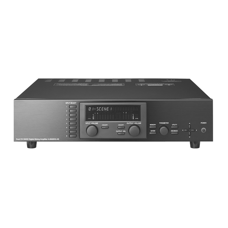
9000 Series Power Amplifier
Dual CH 500W Digital Mixing Amplifier A-9500D2-AS 1CE
Please also read the separate instruction manual for the programming software in conjunction
with this manual.
Thank you for purchasing TOA's 9000 series Amplifier.
Please carefully follow the instructions in this manual to ensure long, trouble-free use of your equipment.
Note:All the 9000 series in this manual refer to CP-9500M2-EB and A-9500D2-AS 1CE.
INSTALLATION AND
OPERATING INSTRUCTIONS
(Applicable to the 9000M2
firmware Ver. 2.00 or later)
CP-9500M2-EB
Advertisement
Table of Contents


Need help?
Do you have a question about the CP-9500M2-EB and is the answer not in the manual?
Questions and answers