Sign In
Upload
Manuals
Brands
Toa Manuals
Amplifier
CP-9500M2-EB
Toa CP-9500M2-EB Manuals
Manuals and User Guides for Toa CP-9500M2-EB. We have
1
Toa CP-9500M2-EB manual available for free PDF download: Installation And Operating Instructions Manual
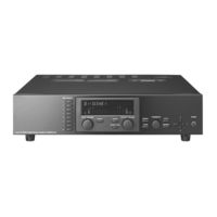
Toa CP-9500M2-EB Installation And Operating Instructions Manual (155 pages)
9000 series power amplifer dual CH 500W digital mixing amplifier
Brand:
Toa
| Category:
Amplifier
| Size: 6.75 MB
Table of Contents
Table of Contents
2
1 Important Safety Instructions
6
2 Safety Precautions
7
3 General Description
9
4 Features
10
5 Installation Precautions
11
6 Handling Precautions
11
Nomenclature and Functions(Example for Cp-9500M2-Eb)
12
CP-9500M2-EB Amplifier
12
[Front]
12
[VFD On-Screen Indications]
13
[Changing the Indicated Channels on the LEVEL Output Meter]
15
[Changing the Input and Output Meter Display Status]
15
[Rear]
16
Optional Modules
17
D-001T and D-001R (2-Channel Input Modules)
17
T-001T (Audio Output Expansion Module)
17
ZP-001T (Zone Paging Module)
18
C-001T (Control I/O Expansion Module)
19
AN-001T (Ambient Noise Sensor Input Module)
19
RC-001T (Remote Control Module)
20
Optional Accessories
21
AN-9001 (Ceiling Mount Microphone)
21
ZM-9001 (Zone Manager)
22
ZM-9002 (Zone Manager)
23
ZM-9003 (Zone Manager)
24
ZM-9011 (Remote Control Panel)
25
ZM-9012 (Remote Control Panel)
26
ZM-9013 (Remote Control Panel)
27
ZM-9014 (Remote Control Panel)
28
SS-9001 (Speaker Selector)
30
8 Operation Outline
31
Using as a Mixer Amplifier
31
Using as a Paging Amplifier
32
Paging Using the D-001T, D-001R, or 900 Series Module
32
Paging Using the ZP-001T Module
33
Cross Point ON/OFF Control Using the Remote Controller
36
Glossary
40
9 Operation
43
Basic Operation
43
Keys and Knobs
43
Power ON/OFF
43
Changing the Input Parameters
43
Changing the Output Parameters
44
Input Channel ON/OFF
44
Output Channel ON/OFF
44
Recalling Scene Memory
45
Making Zone Paging
46
Zone Paging Using the D-001T, D-001R, or 900 Series Module
46
Zone Paging Using the ZP-001T Module
48
Releasing Key Lock
50
Operation Example
51
10 Settings
52
Setting Menu Configuration and Flow for Entering each Screen
52
Input Setting Configuration
52
Output Setting Configuration
52
Utility Setting Configuration
53
Scene Memory Setting Configuration
53
Confirming Set Items
53
Input Setting Flow Chart
54
Input Setting Flow Chart for the Channel on Which the D-001T or D-001R Is Used
54
Input Setting Flow Chart for the Channel on Which the ZP-001T Is Used
56
Input Setting Flow Chart for the Channel on Which the AN-001T Is Used
57
Input Setting Items
58
Output Setting Flow Chart
69
Output Setting Items
70
UTILITY Setting Flow Chart
75
Control Input Terminal's Function Settings
77
Control Output Terminal's Function Settings
77
Utility Setting Items
78
Key Lock Function Setting
90
Keys that Can be Locked
90
Password Setting
91
Key Lock Setting Operation
92
SCENE MEMORY Setting Flow Chart
93
Scene Memory Setting Items
94
11 How to Store or Erase Scene Memory
96
Recalling Scene Memory
96
Storing Scene Memory
97
Erasing Scene Memory
98
Setting the Scene Memory to be Recalled at Power-On
99
12 Restoring Factory Default Setting
100
Default Setting Table
101
Items Regarding System Settings
101
Items Regarding Scene Settings
103
Items Regarding Paging Settings
105
13 Module Installation
106
Module Combination
106
Channel Numbers and Terminal Numbers
106
Module Installation Examples
108
Connections(Example for Cp-9500M2-Eb)
109
Control I/O Terminal Connections
109
When a Variable Resistor or Variable DC Power Supply Unit Is Connected
109
When the ZM-9001 or ZM-9002 Is Connected
110
When the ZM-9003 Is Connected
110
When the SS-9001 Is Connected
110
Operation by Control Input
111
Speaker Output Terminal Connections
112
C-001T Module Connections
112
Control Input Terminal
112
Control Output Terminal
112
Connecting the ZM-9003
113
Connecting the SS-9001
113
RC-001T Module Connection
114
Connection Method
114
Cable Distance
115
RS-232C Connector Connection
118
AN-001T and AN-9001 Connections
118
Power Source Connections to the SS-9001
119
When Using a 24 V DC Power Source
119
When Using the Optional AC Adapter
119
Removable Terminal Plug Connection
120
15 Rack Mounting Bracket Attachment
121
16 Cleaning the Filter
122
17 An-9001 Installation
123
18 Dimensional Diagrams
124
An-9001
124
Zm-9001
125
Zm-9002
125
Zm-9003
126
Zm-9011
127
Zm-9012
127
Zm-9013
128
Zm-9014
129
Ss-9001
130
19 Outline of the Attached Software
131
20 Error Indications
132
21 Troubleshooting
133
22 Block Diagram
134
23 Signal Flow Diagram
135
24 Level Diagram
136
25 Compression Characteristics Diagram
137
26 Speaker Preset Parameter List
138
27 Specifications
144
Cp-9500M2-Eb and A-9500D2-As 1Ce
144
Optional Modules
145
D-001T
145
D-001R
146
T-001T
147
C-001T
148
Zp-001T
148
An-001T
149
Rc-001T
149
Optional Accessories
150
An-9001
150
Zm-9001
150
Zm-9002
151
Zm-9003
151
Zm-9011
152
Zm-9012
152
Zm-9013
153
Zm-9014
153
Ss-9001
154
Advertisement
Advertisement
Related Products
Toa CA-115
Toa CA-130
Toa CA-160
Toa C-001T
Toa CP-63
Toa CP-66
Toa CPU-56
Toa CPU-52A
Toa CP-62
Toa CPU-55
Toa Categories
Speakers
Amplifier
Intercom System
Speaker System
Microphone
More Toa Manuals
Login
Sign In
OR
Sign in with Facebook
Sign in with Google
Upload manual
Upload from disk
Upload from URL