Table of Contents
Advertisement
Advertisement
Table of Contents

Related Manuals for Pegatron IPMTB-GS


Summary of Contents for Pegatron IPMTB-GS
- Page 1 IPMTB-GS Motherboard Reference Guide...
-
Page 2: Table Of Contents
5 Expansion slots ................... 15 Installing an expansion card ............15 6 Selectors ....................16 7 Connectors ................... 17 8 BIOS Setup reference ................23 Main ....................23 Advanced ...................24 Power ..................25 Security ..................26 Boot ....................28 Exit .....................29 IPMTB-GS Motherboard Reference Guide... -
Page 3: Notices
This digital apparatus does not exceed the Class B limits for radio noise emissions from digital apparatus set out in the Radio Interference Regulations of the Canadian Department of Communications. This class B digital apparatus complies with Canadian ICES-003. IPMTB-GS Motherboard Reference Guide... -
Page 4: Safety Information
IMPORTANT: This symbol of the crossed out wheeled bin indicates that the product (electrical and electronic equipment) should not be placed in municipal waste. Check local regulations for disposal of electronic products. IPMTB-GS Motherboard Reference Guide... -
Page 5: Specifications Summary
1x SPDIF output connector 1x IEEE1394 connector 3x USB2.0 connectors 1x ROM recovery connector 1x Front panel connector BIOS AMI 8Mb SPI Form factor microATX: 9.6 in. x 9.6 in. *The specifications are subject to change without notice. IPMTB-GS Motherboard Reference Guide... -
Page 6: Hardware Installation
Failure to do so can cause you physical injury and damage motherboard components. Package contents Check your package for the following items. Motherboard 1x IPMTB-GS Cables Accessories 1x I/O shield Support disc 1x Drivers & Utilities Documentation 1x This Motherboad Reference Guide IPMTB-GS Motherboard Reference Guide... -
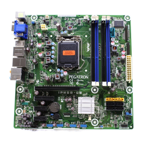
Page 7: Motherboard Layout
Orange: Center/ Subwoofer output IEEE1394 LAN (RJ-45) Black: Rear Surround L/R output port port Blue: Line input Lime: Front L/R output Pink: Microphone input SPDIF eSATA ports USB 2.0 ports Gray: Side surround L/R output output port IPMTB-GS Motherboard Reference Guide... -
Page 8: Central Processing Unit (Cpu)
3. Move it to the left (B) until it is This side of the cam box released from the retention tab. should face you. NOTE: To prevent damage to the socket pins, do not remove the socket cap unless you are installing a CPU. IPMTB-GS Motherboard Reference Guide... - Page 9 8. Close the load plate (A), then push the load lever (B) until it snaps into the retention tab. Alignment key Gold triangle mark NOTE: The CPU fits in only one correct orientation. DO NOT force the CPU into the socket to prevent damaging the delicate CPU! IPMTB-GS Motherboard Reference Guide...
-
Page 10: Installling The Cpu Heatsink And Fan
2. Push down two fasteners at a time in a 3. When the fan and heatsink assembly is in place, connect the CPU fan diagonal sequence to secure the heatsink cable to the connector on the motherboard. and fan assembly in place. CPU FAN IPMTB-GS Motherboard Reference Guide... -
Page 11: Uninstalling The Cpu Heatsink And Fan
4. Remove the heatsink and fan assembly from the motherboard. 5. Rotate each fastener clockwise to reset the orientation. NOTE: The narrow end of the groove should point outward after resetting. IPMTB-GS Motherboard Reference Guide... -
Page 12: System Memory
2. Insert 2GB modules first, then 1GB modules if both are used. 3. Fill each channel (two sockets) with modules to fully utilize triple channel performance. IMPORTANT: One of the blue sockets (DIMM1/3/5) must be populated. IPMTB-GS Motherboard Reference Guide... - Page 13 (Ch B, (Ch C, (Ch C, Memory Configuration Black) Blue) Black) Blue) Black) Blue) Dual Triple Dual Triple (unbalanced) Triple (unbalanced) Triple Triple (unbalanced) Triple (unbalanced) Triple Triple (unbalanced) Triple 10GB (unbalanced) Triple 11GB (unbalanced) 12GB Triple IPMTB-GS Motherboard Reference Guide...
-
Page 14: Installing A Dimm
DIMM. 2. Remove the DIMM from the socket. DDR3 DIMM notch TIP: Support the DIMM lightly with your fingers when pressing the retaining clips. The DIMM might get damaged when it flips out with extra force. IPMTB-GS Motherboard Reference Guide... -
Page 15: Expansion Slots
4. Align the card connector with the slot and press firmly until the card is completely seated on the slot. 5. Secure the card to the chassis with the screw you removed earlier. 6. Replace the system cover. IPMTB-GS Motherboard Reference Guide... -
Page 16: Selectors
3. Turn ON the computer to POST screen. 4. Turn OFF the computer. 5. Move the cap back to Default. 6. Enter BIOS setup to verify or configure new settings. 1 3 5 1 3 5 Normal (Default) Clear Password IPMTB-GS Motherboard Reference Guide... -
Page 17: Connectors
+3 Volts +5 Volts +12 Volts +5 Volts +12 Volts +5V Standby +5 Volts Power OK Ground Ground +5 Volts Ground Ground Ground +5 Volts PSON# Ground Ground +3 Volts 12 Volts +3 Volts +3 Volts ATX_CPU IPMTB-GS Motherboard Reference Guide... - Page 18 Rotation Ground +12V Rotation Audio line in connector (optional) This connector allows you to receive stereo audio input from sound sources such as an optical disc drive, a TV tuner, or a specialized audio/sound-processing card. F_LINE-IN IPMTB-GS Motherboard Reference Guide...
-
Page 19: Usb Connectors
These USB connectors comply with USB 2.0 specification that supports up to 480 Mbps connection speed. WARNING: Never connect a 1394 cable to the USB connectors. Doing so will damage the motherboard! F_USB4 F_USB3 F_USB2 IPMTB-GS Motherboard Reference Guide... - Page 20 This connector is for the S/PDIF audio module to allow digital sound output. Connect one end of the S/PDIF audio cable to this connector and the other end to the S/PDIF module (may require separate purchase). SPDIF_OUT2 Ground SPDIF Out IPMTB-GS Motherboard Reference Guide...
-
Page 21: Front Panel Audio Connector
ROM Recovery connector This connector allows qualified technicians to reload firmware into the SPI boot flash in case there is problem with the data. ROM_RECOVERY IPMTB-GS Motherboard Reference Guide... - Page 22 Pressing the power switch for more than four seconds while the system is ON turns the system OFF. Reset button (2-pin RESET) This 2-pin connector is for the chassis-mounted reset button for system reboot without turning off the system power. IPMTB-GS Motherboard Reference Guide...
-
Page 23: Bios Setup Reference
Displays the auto-detected BIOS information. System Memory Displays the auto-detected system memory information. System Time [xx:xx:xx] This item allows you to set the system time. System Date [Day xx/xx/xxxx] This item allows you to set the system date. IPMTB-GS Motherboard Reference Guide... -
Page 24: Advanced
The items in this menu allow you to view or change hardware health settings such as voltages, cooling fan performance, temperatures, hard drive status. Actual items vary by system. Spread Spectrum Configuration The items in this menu allow you to view or change spread spectrum configurations. IPMTB-GS Motherboard Reference Guide... -
Page 25: Power
When set to [Power On], the system goes on after an AC power loss. When set to [Last State], the system goes into either off or on state, whatever the system state was before the AC power loss. Default: [Power On] IPMTB-GS Motherboard Reference Guide... -
Page 26: Security
Password then press <Enter>. The message “Password Uninstalled” appears. NOTE: If you forget your BIOS password, you can clear it by erasing the CMOS Real Time Clock (RTC) RAM. See your hardware documentation for information on how to erase the RTC RAM. IPMTB-GS Motherboard Reference Guide... -
Page 27: Change User Password
When set to [Setup], BIOS checks for user password when accessing the Setup utility. When set to [Always], BIOS checks for user password both when accessing Setup and booting the system. Default: [Setup] / Options: [Setup] [Always] IPMTB-GS Motherboard Reference Guide... -
Page 28: Boot
The items in this menu allow you to view or change the hard disk devices settings. Removable Drives The items in this menu allow you to view or change the removable devices settings. CD/DVD Drives The items in this menu allow you to view or change the CD/DVD devices settings. IPMTB-GS Motherboard Reference Guide... -
Page 29: Exit
Discard Changes This option allows you to discard the selections you made and restore the previously saved values. After selecting this option, a confirmation appears. Select Ok to discard any changes and load the previously saved values. IPMTB-GS Motherboard Reference Guide... - Page 30 This option allows you to load the optimal default values for each of the parameters on the Setup items. When you select this option, a confirmation window appears. Select Yes to load the optimal default values. Select Save Changes and Exit or make other changes before saving. IPMTB-GS Motherboard Reference Guide...
Need help?
Do you have a question about the IPMTB-GS and is the answer not in the manual?
Questions and answers