Table of Contents
Advertisement
Advertisement
Table of Contents

Related Manuals for Pegatron IPMIP


Summary of Contents for Pegatron IPMIP
- Page 1 IPMIP Motherboard Reference Guide...
-
Page 2: Table Of Contents
Main BIOS Screen................. 22 Standard BIOS Features ............... 23 Advanced BIOS Features..............24 Advanced Chipset Features ..............27 Boot Configuration Features ..............28 Power Management Features ............... 30 PnP/PCI Configurations ................ 32 PC Health Status ................... 33 Exiting....................36 IPMIP Motherboard Reference Guide... -
Page 3: Notices
This digital apparatus does not exceed the Class B limits for radio noise emissions from digital apparatus set out in the Radio Interference Regulations of the Canadian Department of Communications. This class B digital apparatus complies with Canadian ICES-003. IPMIP Motherboard Reference Guide... -
Page 4: Safety Information
IMPORTANT: This symbol of the crossed out wheeled bin indicates that the product (electrical and electronic equipment) should not be placed in municipal waste. Check local regulations for disposal of electronic products. IPMIP Motherboard Reference Guide... -
Page 5: Specifications Summary
1x Internal serial (COM) port connector 1x Parallel port connector 1x Front panel audio connector 1x SPDIF output connector 1x TPM connector 1x Front panel connector AMI 64Mb BIOS uATX 9.6 inches x 8.0 inches Form factor IPMIP Motherboard Reference Guide... -
Page 6: Hardware Installation
Failure to do so can cause you physical injury and damage motherboard components. Package contents Check your package for the following items. • Motherboard • Cables • Accessories • Drivers & Utilities Support disc • This Motherboad Reference Guide IPMIP Motherboard Reference Guide... -
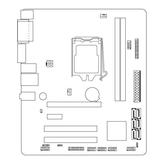
Page 7: Motherboard Layout
Rear panel connectors Mouse (PS/2) port LAN (RJ-45) port Audio connectors Serial (COM1) port Blue: Line In Green: Front-L/R out Pink: Mic In Keyboard (PS/2) port Display (DVI-I ) port Display (VGA ) port USB 2.0 ports IPMIP Motherboard Reference Guide... -
Page 8: Central Processing Unit (Cpu)
6. Lower the load plate so it is resting on the CPU. 7. Pull back the load lever again to ensure the load plate tip engages under the shoulder screw cap. 8. Carefully close and latch the load lever. IPMIP Motherboard Reference Guide... -
Page 9: Installling The Cpu Heatsink And Fan
2. Push down two fasteners at a time 3. When the fan and heatsink assembly is in place, in a diagonal sequence to secure the connect the CPU fan cable to the connector on the heatsink and fan assembly in place. motherboard. CPU_FAN IPMIP Motherboard Reference Guide... -
Page 10: Uninstalling The Cpu Heatsink And Fan
4. Remove the heatsink and fan assembly from the motherboard. 5. Rotate each fastener clockwise to reset the orientation. NOTE: The narrow end of the groove should point outward after resetting. IPMIP Motherboard Reference Guide... -
Page 11: System Memory
WARNING: Only DDR3 RAM modules can be used on this motherboard. The figure illustrates the location of the DDR3 DIMM sockets: IMPORTANT: Always install DIMMs with the same CAS latency. For optimum compatibility, it is recommended that you obtain memory modules from the same vendor. IPMIP Motherboard Reference Guide... -
Page 12: Installing A Dimm
DIMM. 2. Remove the DIMM from the socket. DIMM notch TIP: Support the DIMM lightly with your fingers when pressing the retaining clips. The DIMM might get damaged when it flips out with extra force. IPMIP Motherboard Reference Guide... -
Page 13: Expansion Slots
4. Align the card connector with the slot and press firmly until the card is completely seated on the slot. 5. Secure the card to the chassis with the screw you removed earlier. 6. Replace the system cover. IPMIP Motherboard Reference Guide... -
Page 14: Selectors
To enable or disable the Flash Override: 1. Turn OFF the computer and unplug the power cord. 2. Move the cap to the enable (default) or disable position. 3. Plug the power cord and turn ON the computer. Enable Disable (Default) IPMIP Motherboard Reference Guide... -
Page 15: Connectors
+5 Volts +12 Volts +5 Volts +12 Volts +5 Volts +5V Standby Power OK 5 Volts Ground Ground +5 Volts Ground Ground Ground +5 Volts PSON# Ground Ground +3 Volts 12 Volts +3 Volts +3 Volts ATX_CPU IPMIP Motherboard Reference Guide... -
Page 16: Serial Ata Connectors
Serial ATA connectors These connectors are for the Serial ATA signal cables for Serial ATA devices. SATA1 SATA0 Ground Ground SATA_TX(+) SATA_RX(+) SATA_TX(-) SATA_RX(-) Ground Ground SATA_RX(-) SATA_TX(-) SATA_RX(+) SATA_TX(+) Ground Ground SATA3 SATA2 SATA5 SATA4 IPMIP Motherboard Reference Guide... -
Page 17: Parallel Port Connector
Internal serial port connector This connector is for a serial (COM) port. Connect the serial port module cable to this connector, then install the module to the system chassis. SERIAL_B RRT*# CCTS*# RRTS*# DDSR*# Ground DDTR*# TTXD* RRXD* DDC*# IPMIP Motherboard Reference Guide... -
Page 18: Front Panel Audio Connector
This connector is for the S/PDIF audio module to allow digital sound output. Connect one end of the S/PDIF audio cable to this connector and the other end to the S/PDIF module (may require separate purchase). SPDIF_OUT IPMIP Motherboard Reference Guide... -
Page 19: Chassis Intrusion Connector
This connector is for a chassis-mounted intrusion detection sensor or switch. If enabled the chassis intrusion sensor or switch sends a high-level signal to this connector when a chassis component is removed or replaced. The signal is then generated as a chassis intrusion event. INTRUDER INTRUDER# Ground IPMIP Motherboard Reference Guide... - Page 20 Connect the fan cables to the fan connectors on the motherboard, making sure that the black wire of each cable matches the ground pin of the connector. SYS_FAN1 Ground CHA FAN PWR CHA FAN IN CHA FAN PWM IPMIP Motherboard Reference Guide...
- Page 21 Pressing the power switch for more than four seconds while the system is ON turns the system OFF. Reset button (2‑pin RESET) This 2-pin connector is for the chassis-mounted reset button for system reboot without turning off the system power. IPMIP Motherboard Reference Guide...
-
Page 22: Bios Setup Reference
Find the load default options under the Exit Menu. Main BIOS Screen The BIOS setup screens shown in this section are for reference purposes only, and may not exactly match what you see on your screen. IPMIP Motherboard Reference Guide... -
Page 23: Standard Bios Features
Displays the system’s auto-detected processor information. System Memory Displays the auto-detected system memory information. System Time [xx:xx:xx] This item allows you to set the system time. System Date [Day xx/xx/xxxx] This item allows you to set the system date. IPMIP Motherboard Reference Guide... -
Page 24: Advanced Bios Features
Default: [Enabled] / Options: [Disabled] [Enabled] EIST Default: [Enabled] / Options: [Disabled] [Enabled] Limit CPUID MaxVal Default: [Disabled] / Options: [Disabled] [Enabled] Hyper Threading Default: [Enabled] / Options: [Disabled] [Enabled] CPU Host Clock Display field only: x.xxGHz IPMIP Motherboard Reference Guide... -
Page 25: Ide Configuration
This item allows you to change the USB 2.0 Controller setting. Default: [Enabled] / Options: [Disabled] [Enabled] USB Keyboard/Mouse Support This item allows you to enable or disable support for USB keyboard or Mouse. Default: [Enabled] / Options: [Disabled] [Enabled] IPMIP Motherboard Reference Guide... - Page 26 This item allows you to enable or disable the Onboard LAN Boot ROM. Default: [Enabled] / Options: [Disabled] [Enabled] Keyboard Select Default: [Keyboard 1] ACPI APIC Support This item allows you to enable or disable ACPI APIC Support. Default: [Enabled] / Options: [Disabled] [Enabled] PAVP Mode Default: [Lite] IPMIP Motherboard Reference Guide...
-
Page 27: Advanced Chipset Features
Default: [Disabled] / Options: [Disabled] [Enabled] Trusted Computing Trusted Computing enforces the computer to consistently behave in expected ways by hardware and software. This allows verification that only authorized code runs on the system. Initiate Graphic Adapter Default: [PCI/PCIE] IPMIP Motherboard Reference Guide... -
Page 28: Boot Configuration Features
This item allows you to select the power-on state for the NumLock. Default: [On] / Options: [Off] [On] Full Screen Logo Default: [Enabled] / Options: [Disabled] [Enabled] Halt On This item allows you to change the Halt On setting. Default: [ALL But KeyBoard] IPMIP Motherboard Reference Guide... - Page 29 Hard Disk Priority These items specify the boot device priority sequence from the available hard disks. The number of hard disks that appears on the screen depends on the number of hard disks installed in the system. IPMIP Motherboard Reference Guide...
-
Page 30: Power Management Features
Default: [Enabled] / Options: [Disabled] [Enabled] EUP Mode This item allows you to enable or disable EUP Mode. Default: [Disabled] APM Configuration Resume By PME# Default: [Enabled] / Options: [Disabled] [Enabled] Power On By Ring Default: [Disabled] / Options: [Disabled] [Enabled] IPMIP Motherboard Reference Guide... - Page 31 This item allows you to change the Power On RTC Alarm setting. Default: [Disabled] / Options: [Disabled] [Enabled] Restore on AC Power Loss Default: [Power Off] Power Button Mode This item allows you to change the system’s behaviour when the power button is pressed. Default: [On/Off] IPMIP Motherboard Reference Guide...
-
Page 32: Pnp/Pci Configurations
8 BIOS Setup reference PnP/PCI Configurations Clear NVRAM This item allows you to enable or disable Clear NVRAM feature. Default: [Disabled] / Options: [Disabled] [Enabled] Plug & Play O/S Default: [No] IPMIP Motherboard Reference Guide... -
Page 33: Pc Health Status
Default: [040] Slope PWM/ºC This item allows you to configure the temperature slope setting. Default: [006] Delta Temp This item allows you to configure the delta temperature setting. Default: [003] Full Speed Offset Display field only: [-xx] IPMIP Motherboard Reference Guide... - Page 34 PC Health Status CPU Temperature Display field only: [-xx] Vcore Voltage Display field only: x.xxx V 3.3V Voltage Display field only: x.xxx V 5V Voltage Display field only: x.xxx V 12V Voltage Display field only: x.xxx V IPMIP Motherboard Reference Guide...
-
Page 35: Bios Security Features
Password then press <Enter>. The message “Password Uninstalled” appears. NOTE: If you forget your BIOS password, you can clear it by erasing the CMOS Real Time Clock (RTC) RAM. See your hardware documentation for information on how to erase the RTC RAM. IPMIP Motherboard Reference Guide... -
Page 36: Exiting
NOTE: If you attempt to exit the Setup program without saving your changes, the program prompts you with a message asking if you want to save your changes before exiting. Press <Enter> to save the changes. IPMIP Motherboard Reference Guide... - Page 37 Select this option only if you do not want to save the changes that you made to the Setup program. If you made changes to fields other than System Date, System Time, and Password, the BIOS asks for a confirmation before exiting. IPMIP Motherboard Reference Guide...
Need help?
Do you have a question about the IPMIP and is the answer not in the manual?
Questions and answers
Preciso fazer recovery na minha placa, como devo jampear? Minha placa IPMIP-GS
To jumper for recovery (Flash Override) on the Pegatron IPMIP-GS motherboard:
1. Turn OFF the computer and unplug the power cord.
2. Move the jumper cap to the "Enable" position on the Flash Override selector.
3. Plug the power cord back in and turn ON the computer.
4. After recovery, move the cap back to the default position.
Note: Do not leave the jumper in the "Enable" position after use, as it may cause system boot failure.
This answer is automatically generated