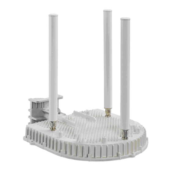
Wavion WBS-2400 Installation Manual
Outdoor wi-fi base station
Hide thumbs
Also See for WBS-2400:
- User manual (116 pages) ,
- Installation manual (74 pages) ,
- User manual (108 pages)

Related Manuals for Wavion WBS-2400


Summary of Contents for Wavion WBS-2400
- Page 1 WBS-2400 & WBS-5800 & WBS-5000P Outdoor Wi-Fi Base Station Installation Guide Rev. 7 March 2012...
- Page 2 Note: To better reflect the value of Wavion products we are changing the name of our product family from Access Points (AP) to Wireless Base Stations (WBS), consequently the existing WS- 410 product name will be changed to Wavion WBS-2400.
- Page 3 Note This device complies with part 15 of the FCC Rules. Operation is subject to the following two conditions: (1) This device may not cause harmful interference, and (2) this device must accept any interference received, including interference that may cause undesired operation. R&TTE Compliance Statement This equipment (ETSI-models only) complies with all the requirements of DIRECTIVE 1999/5/CE OF THE EUROPEAN PARLIAMENT AND THE COUNCIL of March 9, 1999 on...
-
Page 4: Table Of Contents
Antenna Sealing ..................22 Connecting Power and DATA - Option 1 ........... 26 Connecting Power and DATA - Option 2 ........... 30 Safety Information for the Wavion WBS-2400/5800/5000P......33 Service Instructions ................34 Product Specification WBS-2400 ..........35 C h a p t e r 5 Antenna 2.4GHz Specifications and Patterns ...... -
Page 5: About This Guide
Chapter 1 About This Guide Preface This guide details the Wavion WBS-2400/5800/5000P installation procedures. The intended audience of this document is trained technical professionals. Conventions The exclamation point within a triangle is intended to alert the user to the presence of important operating and maintenance (servicing) instructions in the literature accompanying the product. -
Page 6: Contacting Technical Support
About This Guide Contacting Technical Support For technical support, contact Wavion using these methods: Wavion Technical Support Wavion 6 Hayetzira Street, Address: PO BOX 580 Yoqneam Illit, 20692 Israel Telephone: +972-4-9097380 Fax: +972-4-9097322 support@wavionnetworks.com Email: www.wavionnetworks.com Web: Wavion Networks... -
Page 7: Introduction
A system can include any number of cells, each containing several base station access units for better coverage of densely populated areas. It is based on six antennas and radios and custom-built ASICs, utilizes Wavion's powerful multi- antenna signal processing technologies, and provides significant performance gains to off-the- shelf 802.11 standards-based... -
Page 8: Package Content
(reset button and Link LED). Using cross cable might cause turn Link led to “ON” permanently and also may be the cause software reset. DATA cable connecting the injector to the network can be cross cable as well. Wavion Networks... - Page 9 Failure to do so may void the WBS-2400/5800/5000P product warranty and may expose the end user or Service Provider to legal and financial liabilities. Wavion and its resellers or distributors are not liable for injury, damage or regulation violations associated with the installation of...
-
Page 10: Station
Chapter 4 Installing the Wavion WBS OMNI Metro Base Station This guide explains how to safely install the Wavion WBS-2400/WBS-5800/WBS-5000P Metro Base Station. The following topics are covered in this chapter: Important Safety Instructions Preparing for Installation ... -
Page 11: Important Safety Instructions
Warning: Risk of personal injury or death when installing this device! There is a risk of personal injury or death if the WBS-2400/5800/5000Pantennas come near electric power lines. Carefully read and follow all instructions in this manual. By nature of the installation, you may be exposed to hazardous environments and high voltage. -
Page 12: Preparing For Installation
Caution The WBS-2400/5800/5000P/5000P must be installed only with the equipped antennas. Caution A minimum distance of 40cm from the WBS-2400/5800/5000P/5000P antenna should be kept when the system is operated. Caution Read and save these instructions. Heed all warnings. Follow all... -
Page 13: Choosing A Location
Choosing a Location To ensure the optimal performance select the locations for the equipment using the following guidelines: The antenna (not-integrated on the front panel of the outdoor unit) should provide a direct, or near line of sight, with the sector location that need to be covered. -
Page 14: Mounting Strategies
It is recommended to attach ground and data cables to the WBS-2400/5800/5000P prior to mounting. Before mounting the WBS-2400/5800/5000P, read the wiring instructions in... -
Page 15: Using Hose Clamps
Figure 4.2 Example Mounting Locations on a Streetlight Using Hose Clamps Special hose clamps that include threaded holes are used by the mounting assembly to secure the WBS-2400/5800/5000P/5000P to the mounting structure. F igure 4.3 demonstrate how to correctly use the hose clamps. The bands must be threaded through holes in the pole bracket, and then attached to either a vertical or a horizontal pole and tightened. -
Page 16: Mounting On A Pole/Streetlight
Mounting on a Pole/Streetlight WBS-2400/5800/5000P/5000P can be mounted on a pole, tower, or streetlight. It is recommended to mount the WBS-2400/5800/5000P/5000P on aluminum or galvanized steel structures. Note The Wavion WBS-2400/5800/5000P/5000P must be mounted with the top of the unit parallel with the ground and with the antennas pointing upward. - Page 17 To mount the Wavion WBS-2400/5800/5000P on a metal/wood/streetlight pole: 1. Choose a mounting location. You can attach the WBS-2400/5800/5000P outdoor unit to any pole or pipe with diameter of 3-10 inches. Wooden poles of larger diameter Installation Guide...
- Page 18 2. Slip the bands of the hose clamps through the slots of the pole bracket 3. Use the hose clamps to fasten the pole bracket to the pole. 4. Insert the WBS-2400/5800/5000P onto the pole bracket, obtain the correct position and tighten 4 bolts using 4mm Allen wrench.
- Page 19 Note : The WBS-2400/5800/5000P unit must be parallel to the ground. The unit can be rotated to obtain the correct position. Note Installations on large wooden poles require band clamps such as those supplied by Panduit, www.panduit.com. Such a product is listed as "Metal, Locking Tie Extra Heavy Duty 304 Stainless Steel".
-
Page 20: Grounding The Data Protection Device
To ground the Wavion WBS-2400/5800/5000P: The Grounding screw is located on the side panel of the outdoor unit. To connect the grounding cable: Connect one end of a grounding cable to the grounding terminal and tighten the grounding screw firmly. -
Page 21: Installation Guide
10 AWG wire to ground Earth Ground Earth Ground Earth 10 AWG wire to ground Earth WBS-2400/5800 Wavion POE INJECTOR Power + DATA 110/220VAC Power + DATA Lightning Surge Protector POE cable enters building wall through conduit Customer PC Figure 4.9... -
Page 22: Connecting Antennas
Connecting Antennas This section explains how to connect the six antennas to the WBS-2400/5800/5000PX. In order for the WBS-2400/5800/5000P to work properly, six antennas must be connected. Screw each of the 6 antennas into the N-Type connectors on the WBS-2400/5800/5000P. - Page 23 Caution It is important to read carefully this procedure and perform all its steps to ensure maximal moisture protection. Caution It is important to read carefully this procedure and perform all its steps to ensure maximal moisture protection. Sealing Technique: 1.
- Page 24 4. Tape should be applied in successive half-lapped, level-wound layers until desired build-up is reached 5. Wrap Scotch Super 88 Vinyl Plastic Tape in the same way to cover the splice protection Wavion Networks...
- Page 25 6. Sealing is completed when the connector and the lower part of the antenna are covered with the sealing splicing tape and with vinyl plastic tape Installation Guide...
-
Page 26: Connecting Power And Data - Option 1
Connecting Power and DATA - Option 1 The following describes how to apply power and data to the WBS-2400/5800/5000PX Caution : You must always install an external grounding wire. Perform a simple continuity check between the WBS-2400/5800/5000Pand the ground termination point to confirm. You must also ground the outdoor data protection device to a ground rod or a bonded pipe. - Page 27 See "Grounding the Data protection device" section for connection diagram. 3. Connect one end of the Category 5 cable to the "RADIO" port of the Wavion POE injector. 4. Connect the other cable end to ETH port on the WBS-2400/5800/5000P. Use a shielded RJ45 8-pin modular plug to terminate the cables at the desired lengths.
- Page 28 Figure 4.13 Sealing rubber 7. Remove the strip nylon cover Wavion Networks...
- Page 29 Use high quality sealing material such as Scotch® 130C Linerless Rubber Splicing Tape from 3M to Ensure IP-67 compliant protection against dust and water. 9. Connect the data cable from the network to "Ethernet" port of POE injector. 10. Connect POE injector to AC power source to power WBS-2400/5800/5000Punit. Installation Guide...
-
Page 30: Connecting Power And Data - Option 2
Connecting Power and DATA - Option 2 The following describes how to apply power and data to the WBS-2400/5800/5000P Caution : You must always install an external grounding wire. Perform a simple continuity check between the WBS-2400/5800/5000Pand the ground termination point to confirm. You must also ground the outdoor data protection device to a ground rod or a bonded pipe. - Page 31 See "Grounding the Data protection device" section for connection diagram. 3. Connect one end of the Category 5 cable to the "RADIO" port of the Wavion POE injector. 4. Unscrew the plastic cap and the cap cover from the Wavion WBS- 2400/5800/5000P.
- Page 32 Step 4 Step 3 and Step 4: Screw the plastic cap; make sure it is well tightening. Furthermore screw the cap cover to ensure perfect sealing. It will ensure IP-67 compliance. Figure 4.17 Steps to connect the Ethernet cable. Wavion Networks...
-
Page 33: Safety Information For The Wavion Wbs-2400/5800/5000P
2400/5800/5000Paccording to the instructions found in this manual, results in user exposure that is substantially below the FCC recommended limits. Follow these guidelines to ensure safe operation of the Wavion WBS-2400/5800/5000PX: Do not touch or move the antennas while the unit is transmitting or receiving. -
Page 34: Service Instructions
The Wavion WBS-2400/5800/5000Pmust be used only with Wavion approved components and antennas. Service Instructions The Wavion WBS-2400/5800/5000P contains no user serviceable parts inside. Wavion Networks... -
Page 35: Product Specification Wbs-2400
Chapter 5 Product Specification WBS-2400 The tables in this chapter contain specifications for the Wavion WBS-2400. Wireless Specifications IEEE 802.11b/g compliant Frequency band 2.4 - 2.483 GHz or TBD 802.11b: DSSS (DBPSK, DQPSK, CCK) Modulation 802.11g: OFDM (64QAM, 16QAM, QPSK,... - Page 36 HTTPS for web-based management tools Management Specifications Networking and QoS Specifications Web based configuration and management too Full 802.11b/g client compatibility SNMPv2 with standard and Wavion MIB support 16 VLANs Configuration save and restore 16 SSIDs Network and client statistics...
- Page 37 3.34Kg (without the post-clamp and antenna Power Specifications Power Input 55VDC, supplied over Ethernet from Wavion injector. Power from Wavion Injector max.0.8A @ 55VDC Input Power Power consumption may vary for the different part Consumption numbers – maximum will be 44W.
- Page 38 ETSI 300 328 V1.7.1 (2006) TUVus EN 60950-1:2001+A11:2004 IEC 60950-1:2001 Safety First Edition Information Technology equipment – Safety – Part 1 FCC CFR 47 Part 15, Sub Part B, Class B (USA) ETSI 301 489-4 V1.3.1 (2002), ETSI 301 489-1 V1.5.1 (2003) Wavion Networks...
-
Page 39: Antenna 2.4Ghz Specifications And Patterns
Chapter 6 Antenna 2.4GHz Specifications and Patterns The chapter describes antenna specifications and patterns for the antennas supplied with the Wavion WBS-2400. SF-245W 2.4GHz Omnidirectional Antenna Specifications Pattern 2400-2500MHz Gain: 7.4dBi Length: 17.5 inches Weight: 4.7 oz -3dB Beam-width: 20 degrees... - Page 40 Wavion Networks...
- Page 41 Installation Guide...
- Page 42 Wavion Networks...
-
Page 43: Mt_341017Na_Sn_101_El 2.4 Ghz Antenna
MT_341017NA_SN_101_EL 2.4 GHz Antenna The following describes the patterns for the antenna: Installation Guide... - Page 44 Wavion Networks...
- Page 45 Installation Guide...
-
Page 46: Sf-245W-10Sr 2.4 Ghz Antenna
Cross Polar Rejection: 15dB + Max Power: 50 watts Max wind survival: 150MPH + Wind Load: 7.1 sq in Connector: Integral N-male Radome: White UV stabilized fiberglass Mast mounting hardware optional Mobile lip mount optional Mobile permanent mount optional Wavion Networks... -
Page 47: Product Specification Wbs-5800
Chapter 7 Product Specification WBS-5800 The tables in this chapter contain specifications for the Wavion WBS-5800. Wireless Specifications IEEE 802.11b/g compliant Frequency band 5.725–5.850 GHz 802.11a: OFDM (64QAM, 16QAM, QPSK, Modulation BPSK) • Max. power per antenna: 19dBm (FCC... - Page 48 VPN pass-through and tagging HTTPS for web-based management tools Management Specifications Web based configuration and management too SNMPv2 with standard and Wavion MIB support Configuration save and restore Network and client statistics Networking and QoS Specifications Full 802.11b/g client compatibility...
- Page 49 3.34Kg (without the post-clamp and antenna Power Specifications Power Input 55VDC, supplied over Ethernet from Wavion injector. Power from Wavion Injector max.0.8A @ 55VDC Input Power Power consumption may vary for the different part Consumption numbers – maximum will be 44W.
- Page 50 Approvals FCC CFR 47 part 15, Sub Part C TUVus EN 60950-1:2001+A11:2004 Safety IEC 60950-1:2001 First Edition Information Technology equipment – Safety – Part 1 FCC CFR 47 Part 15, Sub Part B, Class B (USA) Wavion Networks...
-
Page 51: Antenna 5.8Ghz Specifications And Patterns
Chapter 8 Antenna 5.8GHz Specifications and Patterns The chapter describes antenna specifications and patterns for the antennas supplied with the Wavion WBS-5800. MT-462007-N 5.8GHz Omni directional Antenna Frequency Range 4900-5875MHz Peak Gain: 8.5dBi ± 1 dB Regulatory Compliance: RoHS, CE 0682 VSWR: 2.0:1 (max) -
Page 52: Gain Versus Elevation
Gain versus Elevation The following graphs show the gain versus elevation at 0 degrees azimuth angle at the following frequencies: 1. 5.725GHz 2. 5.875GHz Wavion Networks... - Page 53 Installation Guide...
-
Page 54: Installation Accessories
Chapter 9 Installation Accessories This chapter describes the accessories available for the WBS-2400 and ordering information. The following topics are covered in this chapter: Ethernet Cables Sun Protection Lightning Protection Power Over Ethernet Ethernet Cables Part... -
Page 55: Power Over Ethernet
Power Over Ethernet Product Part Description Name Number Wavion Injector for powering the WBS-2400/5800/5000Pover WPI-AC- 27002213 an Ethernet cable. Output 55VDC, 1A. Installation Guide... -
Page 56: C H A P T E
The Wavion WBS-2400/5800/5000Pweighs approximately 16 lbs, including all mounting hardware. When the Wavion WBS-2400/5800/5000Pis mounted on a pole, the sail area of the WBS-2400/5800/5000Pis approximately 1 square foot. The Wavion WBS- 2400/5800/5000Pcan load a pole with a maximum load of 3400 Newton in wind conditions of 165mph. -
Page 57: C H A P T E
Chapter 11 Acronyms Acronym Description Two-Phase or Split Phase Two-Wire Three-Wire Alternating Current ANSI American National Standards Institute American Wire Gauge Celsius Category Complementary Code Keying Code of Federal Regulations Canadian Standard Association Decibels Decibels Relative to an Isotropic Radiator DBPSK Differential-Binary Phase-Shift Keying Direct Current... - Page 58 Multiplexing Phase Protective Earth Power over Ethernet RJ45 Registered Jack 45 Received Signal Strength Receive Receive Data Technical Inspection Association Transmit Transmit Data Underwriters Laboratories Voltage (Alternating Current) VCCI Voluntary Control Council for Interference Voltage (Direct Current) Watts Wavion Networks...
-
Page 59: C H A P T E
Chapter 12 Appendix A: WBS-2400/5800/5000P Product list Part Product name Product description Number Spatially adaptive, multi radio 2.4GHz WiFi base station, 12406101 WBS-2400-FCC 6 antenna FCC/TUV compliant Spatially adaptive, multi radio 2.4GHz WiFi base station, 12406102 WBS-2400-EU 6 antenna ETSI / CE compliant Spatially adaptive, multi radio 2.4GHz WiFi base...
Need help?
Do you have a question about the WBS-2400 and is the answer not in the manual?
Questions and answers