Table of Contents
Advertisement
Quick Links
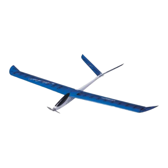
1.4M Electric Powered R/C Sailplane
No.4312 E-HAWK 1400
Wing Span: 55" (1400mm)
Wing Loading: 10oz./sq.ft.(31g/dm
Warranty
:This kit is guaranteed to be free from defects in material and workmanship at the date of
purchase.
It does not cover any damage caused by use or modification. The warranty does not extend
beyond the product itself and is limited only to the original cost of the kit. By the act of building this user-
assembled kit, the user accepts all resulting liability for damage caused by the final product. If the buyer
is not prepared to accept this liability, it can be returned new and unused to the place of purchase for a
refund.
Notice: Adult Supervision Required
product requires adult supervision. Read through this book completely and become familiar with the
assembly and flight of this airplane. Inspect all parts for completeness and damage. Customers in North
America please call 1-949-833-7498 for help if you encounter any problems.
A A l l m m o o s s t t R R e e a a d d y y T T o o F F l l y y
Length: 31" (787mm)
Wing Area: 300 sq.in.(19.4dm
2
)
Motor: 380PH Motor included
2
)
Prop: 6 x 3 Folding Prop included
:This is not a toy. Assembly and flying of this
Weight: 21oz.(600g)
Advertisement
Table of Contents

Related Manuals for THUNDER TIGER hawk 1400


Summary of Contents for THUNDER TIGER hawk 1400
- Page 1 A A l l m m o o s s t t R R e e a a d d y y T T o o F F l l y y 1.4M Electric Powered R/C Sailplane No.4312 E-HAWK 1400 Wing Span: 55" (1400mm) Length: 31”...
-
Page 2: Table Of Contents
INTRODUCTION All of us at Thunder Tiger want to thank you for choosing the E-Hawk.This Kit has been engineered to go together quickly and easily while still providing you with great looks and exceptional flying performance. The world of electric powered sailplanes can be an extremely challenging and rewarding experience. -
Page 3: Pre-Assembly Notes
ASSEMBLY INSTRUCTION PRE-ASSEMBLY NOTES 1. If you are not an experienced R/C pilot plan to have a fully competent pilot help you to learn to fly your E-Hawk. This ACE 8012 ACE 8007 will help you to be successful much faster and also avoid potential damage to your model. -
Page 4: Parts Drawing
PARTS DRAWING Open the box and check that you have all the parts as shown below. If anything is missing please contact your dealer AS6239 Main Wing (T. Magenta) AS6239L Main Wing (T. Blue) Wing Join Wire(1) AS6239Y Main Wing (T. Yellow) Aileron Servo Tray(1) 3x12mm Wood Screw(2) Wing Protector(1) -
Page 5: Wing
ASSEMBLY / WING Wing Assembly 4. Trial fit two wing halves with Wing Join Wire. When 1. Locate CA Hinges and use pins to center the satisfied, apply epoxy to two center wing ribs then hinges in place. accurately aligned and firmly press with each other until it cured. -
Page 6: Tail
ASSEMBLY / TAIL 9. CA the wing protector. Trial fit the main wing onto 6. Mark a centerline and wing mounting holes on the fuselage, then drill 3/64"(2mm) holes at the Wing Protector as shown. marks you drew before. Secure the main wing with furnished wing mounting wood screws. -
Page 7: Motor
ASSEMBLY / TAIL / MOTOR 11. Locate Elevator Control Horn (Back Plate, Control Horn Base, 2 x 25mm Screw, Nylon Horn). Position Back Plate on elevator then drill 3/64" (2mm) holes. Motor / Prop Installation 12. Secure and install the control horns as shown. 15. -
Page 8: Servo
ASSEMBLY / SERVO 19. Install the nylon horn to aileron torque rod. Thread clevis to pushrod then connect the clevis to nylon horn. Z-bend the pushrod at the proper position then connect to the servo horn. You will have to remove the servo horn from the servo to do this step. - Page 9 ASSEMBLY / SERVO 22. Install EZ Connector on servo horn. 25. Refer to manufacturer's Receiver and ESC manual then connect all connectors properly. The ESC and RX are located between battery and motor. You might need two servo extensions at this step. Install the switch on fuselage as shown.
-
Page 10: Canopy
CANOPY / CONTROL THROWS & BALANCING Control Throws Canopy Installation These control throws are merely a starting point for your radio setup and can be tailored to fit your flying style. 1/4" (6mm) Aileron-Low Rate 1/4" (6mm) 1/2" (12mm) Aileron-High Rate 27. -
Page 11: First Flights
FIRST FLIGHTS on the transmitter cause the plane to turn to your left FIRST FLIGHTS (which is the planes r ight). Get the picture? Checks You Should Make For tunately the up and down commands do not change. The easiest way to conquer this problem is to Before you attempt to fly your model you should try and always face your body near the direction the perform some final checks:... -
Page 12: Lauching & Landing
Thank you for purchasing sure that your frequency is not in use by someone this E-Hawk from Thunder Tiger and we look forward else which might cause you model to crash. to providing you with other great R/C products in the Always observe frequency control systems at future.