Table of Contents
Advertisement
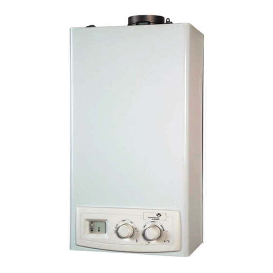
BRITONY SX 14 FF
INSTALLATION, SERVICING AND USER'S MANUAL
Fan Flued Instantaneous Multipoint Water Heater
I
: T
MPORTANT
HIS APPLIANCE IS A DOMESTIC HOT WATER APPLIANCE AND IS INTENDED FOR DOMESTIC USE ONLY
Manufacturers N°
Model Type
Gas Council N°
3675031
Britony SX 14 FF
52 - 980 - 25
c
Country of destination
GB
IE
Advertisement
Table of Contents

Related Manuals for Chaffoteaux & Maury BRITONY SX 14 FF


Summary of Contents for Chaffoteaux & Maury BRITONY SX 14 FF
- Page 1 BRITONY SX 14 FF INSTALLATION, SERVICING AND USER’S MANUAL Fan Flued Instantaneous Multipoint Water Heater MPORTANT HIS APPLIANCE IS A DOMESTIC HOT WATER APPLIANCE AND IS INTENDED FOR DOMESTIC USE ONLY Manufacturers N° Model Type Gas Council N° 3675031 Britony SX 14 FF...
-
Page 2: Table Of Contents
TABLE OF CONTENTS Access to the Gas System Page. 28 GENERAL INFORMATION Page. 3 7.5.1 Removing the gas valve Page. 28 Guarantee Page. 3 8. FAULT FINDING CHART Page. 29 USER INSTRUCTIONS Page. 3 Control Panel Page. 3 9. SHORT SPARES LIST Page. -
Page 3: Guarantee
1. GENERAL INFORMATION The Britony SX Water Heater is a room sealed, fanned flue, mulitpoint water heater. The appliance has been designed for domestic use only and to be connected to a mains cold water supply with a minimum pres- sure of 0.5 bar. -
Page 4: Initial Set-Up
2.2 Initial Set-Up IMPORTANT: The installing technician should explain to the user how the water heater works, the safety devices it includes and how to use it. Before turning the water heater on, it should be connected to the electrical mains via a double pole isolating switch with 3mm contact separation in both poles. -
Page 5: Maintenance
IMPORTANT: In the event that there is a risk of the appliance freezing, close the cold water inlet valve and drain the water heater by opening a hot water tap, see Section 2.5 Useful Information. 2.4 Maintenance Note: Before carrying out any maintenance or repair work on the appliance, the water heater MUST be disconnected from the electrical mains and the gas and water isolating valves MUST be closed. -
Page 6: Installation Instructions
3 INSTALLATION INSTRUCTIONS 3.1 Description of the Appliance SX water heaters are sealed electronic water heaters, with electronic ignition and ionisation safety devices, they have a modulat- ing burner and are connected to the mains water supply; they provide domestic hot water. Their self-contained combustion chambers with fans for the intake of external air and the extraction of combustion products, allow them to operate totally inde- pendently from the room in which they are installed. -
Page 7: Technical Specifications
3.2 Technical Specifications Model Standard, Category and Type SX 14FF Inspection certificate type number 0099BO814 Category 2H3P Destination country Type Degree of protection IP44 Model Symbol Units SX 14 FF Power rating and heat consumption Nominal power output Minimum power output Pmin. -
Page 8: Operating Principle
3.3 Operating Principle 1.- Gas inlet 2.- Cold water inlet 3.- Gas filter 4.- Lower body 5.- Upper body 6.- Water regulator 7.- Test nipple 8.- Water filter 9.- Power selector 10.- Solenoid-valve 11.- Injector 12.- Distributor 13.- Main body 14.- Electrode set 15.- Power supply circuit and control of extraction 16.- Burner... -
Page 9: Appliance Dimensions
3.5 Appliance Dimensions Agujero ø 110 Hole Tubo ø 100 Tube Dimensions (mm) Weight MODEL (kg) 14 litres 60/100 61.5 14.5 3.6 Clearances... -
Page 10: Reference Standards
3.7 Reference Standards In the United Kingdom, the installation and initial start up of the water heater must be by a CORGI Registered installer in accordance with the installation standards curently in effect, as well as with any and all local health and safety standards i.e. -
Page 11: Installing The Water Heater
3.8 Installing the Water Heater The following elements are supplied with the heater : The appliance must be provided with a means of isolation. If installed in a bathroom, the means of isolation must be external 1x Cold water inlet pipe 2x Plastic wall plugs to the bathroom or a double pole cord switch fitted. - Page 12 3.8 Installing the Water Heater Purging the Gas Supply Once all the above checks are complete, it will be necessary to purge the gas supply of air. Do not under any circumstances attempt to purge the gas pipe of air by continually pressing the On/Off button to reset.
-
Page 13: Fitting The Flue
4. FITTING THE FLUE The water heater must only be installed with a flue supplied by the manufacturer. These kits are supplied separately to the appliance in order to respond to different installation solutions. For more information with regard to the inlet/outlet accessories consult the flue brochure and the following instructions. The water heater is supplied ready for connection to a concentric gas intake and exhaust duct system. - Page 14 4.1 Fitting the Coaxial Flue ( 60/100 Horizontal) Continued/..Ø e.g. Clamp X = 508mm - 48mm = 460mm 823 - 460 = 363mm (Length to be cut from the plain end of the flue). Ensure that the inner flue is 23mm longer than the outer flue.
- Page 15 4.2 Fitting the Coaxial Flue ( 60/100 Vertical) Continued/..Ø DO NOT cut the vertical flue kit. To connect the vertical flue kit directly to the boiler, place the vertical starter kit (Part No. 3318008) (see Fig. 15) onto the exhaust manifold and secure with the clamp, fit the Ø125/100 adaptor onto the vertical starter kit (note: there is no need to use a clamp to secure this as it is a push fit con-...
- Page 16 4.3 Fitting the Coaxial Flue ( 60/100 Vertical) Continued/..Ø . 18 . 19 4.4 Fitting the Twin Pipe ( 80/80) Ø EE PAGE FOR MAXIMUM AND MINIMUM FLUE RUNS Where it is not possible to terminate the flue within the dis- tance permitted for coaxial flues, the twin flue pipe can be ARNING Consult the table on Page 18, to see if a restrictor...
- Page 17 4.4 Fitting the Twin Pipe ( 80/80) Continued/..Ø When siting the twin flue pipe, the air intake and exhaust ter- minals must terminate on the same wall, the centres of the 123,5 terminals must be a minimum of 280 mm apart and the air intake must not be sited above the exhaust terminal (refer to Fig.
-
Page 18: Permissible Flue Lengths
4.5 Permissible Flue Lengths Use the Do not use the Maximum Flue Reduction for Reduction for SX 14 FF Exhaust Type ø 85 mm Restrictor Length Bend Bend Restrictor Between Type 1 1 m - 3 m 0.5 m 0.3 m / 1 m Coaxial Between Type 2... - Page 19 5. Comissioning Once the water heater installation has been completed, it is nec- essary to commision the appliance as follows: Gas supply installation Inspect the entire installation including the meter, test for sound- ness and purge, as described in BS 6891. Checking electricity supply Carry out preliminary checks for earth continuity, polarity, resist- ance to earth and short circuit.
-
Page 20: Servicing Instructions
6. SERVICING INSTRUCTIONS To ensure efficient safe operation, it is recommended that the water heater is serviced annually by a competent per- son. Before starting any servicing work, ensure both the gas and electrical supplies to the water heater are isolated and the water heater is cool. -
Page 21: Access To The Combustion Chamber
7.2 Access to the Combustion Chamber 7.2.1 Removing the burner box 1. Carry out step 7.1.1; 4. Pull the burner box towards you 2. Remove the two clips, one on either side of the burner box (Fig. 31 & 32); (Fig. -
Page 22: Removing The Burner
7.2.3 Removing the burner 1. Carry out step 7.1.1 and 7.2.1; 3. Remove the 2 screws D from the 4. Remove the 2 screws E between 2. Disconnect the electrodes wire combustion chamber (Fig. 38); the elbow and the gas valve (Fig. -
Page 23: Removing The Fan
7.2.5 Removing the fan 1. Carry out step 7.1.1; 3. Remove air pressure switch con- 4. Pull the fan towards you (Fig. 2. Remove the fan wires (Fig. 45); nections K (noting position Fig. 43); 49); 4. Remove the screws J & L to free the 5. -
Page 24: Drain Down
7.3 Access to the Water Circuit Important! Before any component is removed, the water heater must be drained of all water. 7.3.1 Drain down 1. Carry out step 7.1.1; 2. Turn OFF the cold water inlet tap on the appliance; 3. -
Page 25: Removing The Water Valve
7.3.3 Removing the water valve 1. Carry out step 7.1.1; 3. Remove the nut between the water valve and the 2. Drain the water heater as in step 7.3.1 by remov- heat exchanger (Fig. 64); ing the screw P (Fig. 63) after turning OFF the water inlet tap and turning ON the water outlet tap;... -
Page 26: Access To The Control System
7.4 Access to the Control System 7.4.1 Removing the control box 1. Carry out step 7.1.1; 3. Remove the gas valve wires 4. Remove the screws R1 & R2 2. Disconnect the electrodes wires (Fig. 69); and pull the control box towards (Fig. -
Page 27: Removing The Fuse
7.4.3 Removing the fuse 4. Remove the fuse (Fig. 79); 1. Carry out step 7.1.1; 3. Remove electrical box cover 5. Reassemble in reverse order. 2. Remove the five screws S on (Fig. 78); the electrical box (Fig. 77); . 77 . -
Page 28: Access To The Gas System
7.5 Access to the Gas System 7.5.1 Removing the gas valve 1. Carry out steps 7.1.1 & 7.3.1; 3. Disconnect the gas valve (Fig. 4. Remove the water valve as in 2. Remove the microswitch as in 84); step 7.3.3 (Fig. 85); step 7.4.4 (Fig. -
Page 29: Fault Finding Chart
8. FAULT FINDING CHART PRELIMARY CHECKS MAKE SURE THAT: 1 - The mains water supply is turned on 2 - The gas is turned on 3 - The electrical supply is turned on PRESS THE ON/OFF BUTTON DRAW OF WATER > 2.3 L/min HAS THE MICROSWITCH CLOSED? - Page 30 FAULTS POSSIBLE CAUSES THERE STILL Drawing D.H.W: - check gas pressures A PROBLEM? insufficient hot water - check water flow rate temperature - check heat exchanger Drawing D.H.W: - heat exchanger faulty or lime-scale deposits noisy operation - low heating system water pressure NORMAL - check gas pressures OPERATION...
- Page 31 9. SHORT SPARES LIST SHORT LIST Manf. date K ey N ° Description G.C N ° Manf . Pt . N° T y p e from FRONT CASE 61400288 KNOB 61400289 FACIA FAN ASSEMBLY 61400261 FAN ASSY 61401861 FAN ASSY 61400262 AIR PRESSURE SWITCH 61401809...
-
Page 32: Commissioning
ERMS AND ONDITIONS OF UARANTEE Please read these terms and conditions which are in On the 12 month anniversary of the appliance installation, addition to any terms and conditions detailed in this book you must have it serviced to continue any guarantee or any registration card supplied with your appliance.
Need help?
Do you have a question about the BRITONY SX 14 FF and is the answer not in the manual?
Questions and answers