Table of Contents
Advertisement
Quick Links
Advertisement
Table of Contents

Related Manuals for Rosewill FBM-05


Summary of Contents for Rosewill FBM-05
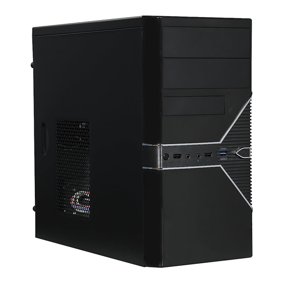
- Page 1 FBM-05...
- Page 2 Please register your product at : http://www.rosewill.com for complete warranty information and future support for your product. If you have any questions while using our products, please visit our website : www.rosewill.com for latest driver & user manual. Support Phone Number: 800-575-9885 Support Email: techsupport@rosewill.com...
-
Page 3: Product Diagram
USB 2.0 CONNECTOR USB 3.0 CONNECTOR HD CONNECTOR None PORT1L AUD GND VBUS VBUS SSRX1- SSRX2- PORT1R SSRX1+ PRESENCE# SSRX2+ ground ground SSTX1- SENSE1_RETURN PORT2R SSRX1+ SSTX2- SENSE_SEND ground SSTX2+ ground PORT2L SENSE2_RETURN None © All rights reserved by Rosewill... -
Page 4: Accessory Kit
User’s Manual CASE FBM-05 Accessory Kit Figure Part’s Name Function M/B Standoff Motherboard Power Supply Screw A Add-in Card Screw B 3.5” HDD Motherboard Screw C 5.25” Device Floppy Motherboard PC Speaker © All rights reserved by Rosewill... -
Page 5: Open The Unit
1-1. Untwist the thumbscrews and slide out panels R and L (Figure 1). Figure 1 2. Install the Power Supply 2-1. Secure the power supply under the top panel with Screw-A (Figure 2). Figure 2 © All rights reserved by Rosewill... -
Page 6: Install The Mainboard
FBM-05 User’s Manual 3. Install the Mainboard 3-1. Line up the standoffs with the screw holes on the mainboard (Figure 3a). Figure 3a 3-2. Screw the mainboard down with Screw-C (Figure 3b). Figure 3b © All rights reserved by Rosewill... -
Page 7: Install The Add-In Card
User’s Manual 4. Install the Add-in Card 4-1. Untwist the screws and remove the slot cover (Figure 4a). Figure 4a 4-2. Install the add-in card and secure with the Screw-B (Figure 4b). Figure 4b © All rights reserved by Rosewill... - Page 8 5-1. Pull the front panel out and remove it (Figure 5a). Figure 5a 5-2. Remove the slot covers (Figure 5b). Figure 5b 5-3. Insert the 5.25” drive and push it back into the case. Secure with Screw-C (Figure 5c). Figure 5c © All rights reserved by Rosewill...
- Page 9 6-1. Insert the external 3.5” device and push it back into the case. Secure with Screw B (Figure 6a). Figure 6a 6-2. Insert the internal 3.5” drive and push it back into the case. Secure with Screw B (Figure 6b). Figure 6b © All rights reserved by Rosewill...
- Page 10 FBM-05 User’s Manual CASE To prevent damage, all panels should remain closed and secured. 7-1. Slide the side panels back into place and secure with thumbscrews (Figure 7). Figure 7 © All rights reserved by Rosewill...
- Page 11 1 x USB 2.0, 1 x USB 3.0, Audio In/Out Front Ports Cooling System 80mm Fans 1 x Rear (pre-installed) 120mm Fans 1 x Top (pre-installed) Side Air duct Physical Specs Dimensions 6.89" x 13.86" x 14.96" (W x H x D) © All rights reserved by Rosewill...
- Page 12 www.rosewill.com...
Need help?
Do you have a question about the FBM-05 and is the answer not in the manual?
Questions and answers