Minuteman E28 User Manual
Hide thumbs
Also See for E28:
- Instruction manual (42 pages) ,
- User manual (38 pages) ,
- Service manual (83 pages)
Table of Contents
Advertisement
Quick Links
Advertisement
Table of Contents

Related Manuals for Minuteman E28


Summary of Contents for Minuteman E28
- Page 1 User Manual E28/E30/E33 (7062.12/.15/.18)
-
Page 2: Introduction
Please observe the unauthorized modification. safety provisions (see chapter "Safety Information”). Your authorized Minuteman dealer will be pleased to answer further questions regarding the vehicle or the operation and maintenance manual. -
Page 3: Notes Of Warranty
Each unit has been tested and through- The maintenance work has to be perfor- ly inspected before shipment. Any da- med by an authorized Minuteman ser- mage is the responsibility of the delivery vice center and confirmed in the carrier who should be notified immedia- "Maintenance certificate"... -
Page 4: Table Of Contents
Stop Machine ... . 11 Batteries ....29 Minuteman Limited Warranty After Work ....11 5.4.4 Remove Batteries. -
Page 5: Safety Information
Safety information Safety information Safety and Warning Symbols All paragraphs in this manual referring to your personal safety, the safety of your machine and the environment pro- tection are attributed one of the follo- wing warning symbols: Safety Symbols Description WARNING Indicates a hazardous situation which could result in death or serious injury. -
Page 6: General Provisions
• Persons being trained by qualified over obstacles (doorsteps). charging procedure and comply with Minuteman technicians only are au- • Only fold open empty recovery tank. the operating instructions of the thorized to operate, service and re- •... -
Page 7: Maintenance Instructions
Battery contact your local Minuteman ser- ting down before working in the area • Observe the operating instructions of vice center. of a lifted tank lid. -
Page 8: Information For Protection Of Environment
Safety information Information for Protection of Environment • For safe use of substances inheriting a danger to health and environment specific knowledge is required. • Observe the legal directives and lo- cal regulations for disposal of deter- gents. • Used batteries labelled as recyclable contain reusable economic goods. -
Page 9: Labels At The Machine
B = Maximum inclination of 2% ne. Replace missing or illegible labels immediately. C = Do not clean the machine by means of high-pressure cleaning equipment Minuteman nameplate (Fig. 1/1) Machine identification number (Fig. 1/2) Recovery tank drain hose (Fig. 1/3) Fig.1... -
Page 10: First Operation
First Operation First Operation maintenance chapter. 3. Install batteries and connect battery Instruction plug, see maintenance chapter. Only persons trained by qualified Minu- 4. Check battery charge and recharge teman technicians are authorized to if required. An initial charge is requi- operate, service and repair the machi- red before first operation of the ma- ne. -
Page 11: Operation
First Operation Operation After Work Transporting the machine 1. Switch on the machine. 1. Move machine to a suitable site for To transport the machine to the work ar- 2. Use lever (Fig5/4) to lower squee- maintenance. ea, switch it on, lift-out squeegee and gee. -
Page 12: Operation
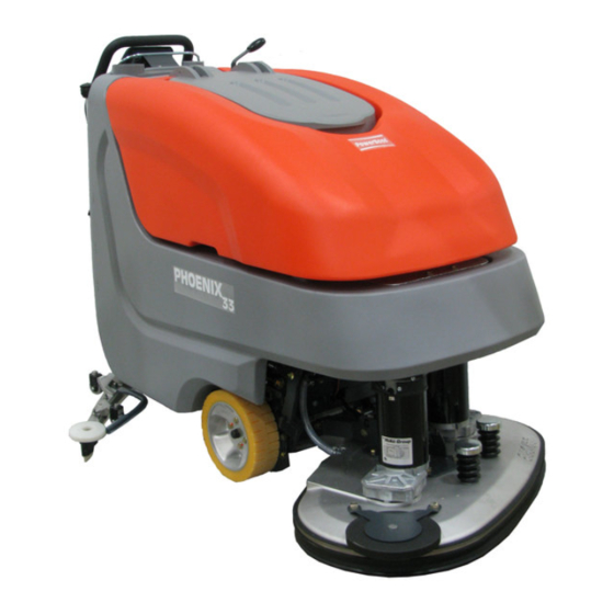
Operation Operation Method of Operation General The E 28/E30/E33 is a vacuum scrub- bing machine for wet cleaning of hard- surfaced floors. 3.1.1 Brush Deck Lower brush deck (Fig. 3/1) via pedal before scrubbing. The brushes rotate and solution supply switches on auto- matically. -
Page 13: Squeegee
Operation 3.1.3 Squeegee 3.1.5 Traction Drive Accessories such as brushes, The movable squeegee (Fig. 3/3) con- The machine features a continuous rollers, pads, pad holder with sists of the squeegee lift mechanism, traction drive (Fig. 3/6). The electronic centerlock and sealing strips the vacuum motor and squeegee bla- traction drive control realises modificati- are available. -
Page 14: Operating And Indicating Ele- Ments
Operation Operating and Indicating Ele- ments 3.2.1 Operating Panel 1 Display 2 Key switch 3 Battery charge indication 4 LDS indicator 5 Symbol brush drive 6 Symbol vacuum drive 7 Hourmeter 8 Symbol Service indicator 9 free 10 Symbol Silence Kit (optional) 11 Symbol solution flow 12 Tip-switch Silence Kit (optional) 13 Tip-switch solution dosage... - Page 15 Operation Display (Fig. 4/1) 1.1.1.1 This panel allows centralized monito- ring of functions and detection of all LDS indicator (Fig. 4/4) Hourmeter (Fig. 4/7) available operating modes. Upon switching on, the LDS indication Upon switching on, the hourmeter is output on the panel to show the cur- briefly displays the software version rent battery charge condition during and the last error code.
- Page 16 Operation free (Fig. 4/9) Solution flow tip-switch (Fig. 4/13) This tip-switch is used to regulate the amount of solution. Additionally, soluti- on amount is adapted to driving speed. The display shows a six-stage symbol Silence Kit tip symbol (optional) for the supplied amount of solution. (Fig.
-
Page 17: At The Machine
Operation 3.2.2 At the machine 1 Brush deck pedal 2 Opening of solution tank 3 Squeegee lever 4 Solution filter 5 Recovery drain hose 6 Solution level indication 7 Brush ejector 8 Power connection charger unit Fig.5... - Page 18 Operation Brush deck pedal(Fig. 5/1) Power connection charger unit (Fig. Use this pedal to lift and lower the brush 5/8) deck. The power connection supplies the charger unit with power. Opening of solution tank (Fig. 5/2) The solution tank is filled after folding up the opening.
- Page 19 Operation Dirt hopper guiding rail (Fig. 6/1) The dirt hopper located at the cylindrical brush deck is fastened by a guiding rail. This dirt hopper may be easily removed for cleaning. Lever for cylindrical brush seating (Fig. 6/2) This lever (both sides) is used to re- lease/lock the cylindrical brush seating.
-
Page 20: Technical Data
Technical Data Technical Data Disc brush deck Cylindrical brush deck 68.0 65.0 Machine length Machine height 43.7 43.7 Machine width without Squeegee 34.7 Machine width with Squeegee 43.3 43.3 Working width 33.5 27.6 Squeegee width 43.3 43.3 Surface performance theoretical 36600 ft²/h 3400... - Page 21 Technical Data Noise emission The sound pressure level measured under maximum conditions of use (LwA) according to DIN EN 60335-2-72 amounts to: dB (A) The sound pressure level measured (at the ear of the driver) under normal condi- tions of use (LpA) according to DIN EN 60335-2-72 amounts to: dB (A) Measurement inaccuracy (KpA): dB (A)
-
Page 22: Maintenance And Care
The Minuteman System Maintenance: To be performed by qualified personnel Before proceeding to mainte- • guarantees reliable operability of the of authorized Minuteman Service Cent- nance and care work you are Minuteman machines (preventive re in accordance with the machine-spe-... -
Page 23: Maintenance Document
Maintenance and Care Maintenance Document Handing over System Maintenance I System Maintenance II System Maintenance I 125 operating hours 250 operating hours 375 operating hours Upgrade Workshop stamp Workshop stamp Workshop stamp Test drive Handing over to the customer Instruction carried out on: carried out on: carried out on:... -
Page 24: Maintenance Schedule
Maintenance and Care Maintenance Schedule System Maintenance Customer The daily and weekly maintenance in- tervals must be performed by the custo- mer/operator. Interval To be performed daily weekly Fill solution tank and proceed to chemical agent dosage Charge batteries Check brush head and clean if required Check squeegee and clean if required Clean tank lid seal of the recovery tank Empty recovery tank. - Page 25 Maintenance and Care System Maintenance I The following maintenance work must be performed by an authorized Minute- man Service workshop. Interval To be performed every 125 hours of operation Check battery charger Check tank lid seal of the recovery tank and replace if required Check drain hose of the recovery tank and replace if required Grease joints at the brush lift-out Check wheel fixing screws and tighten (24 lb ft) if required...
- Page 26 Maintenance and Care System Maintenance II The following maintenance work must be performed by an authorized Minute- man Service workshop. Interval To be performed every 250 hours of operation Perform maintenance works according to System Maintenance I Inspect steering rollers for tread damages and bearing slackness and replace if required Check drain hose of the recovery tank and replace if required Check deflector roller of the brush head and replace if required...
- Page 27 Maintenance and Care System Maintenance S (Safety check) The following maintenance work must be performed by an authorized Minute- man Service workshop at least once a year. Interval To be performed every 500 hours of operation Perform maintenance works according to System Maintenance II Clean travel drive motor from carbon dust and check carbon brushes for smooth operation and wearing and replace carbon brushes if required Clean brush motors from carbon dust and check carbon brushes for smooth opera-...
-
Page 28: Battery Systems
Maintenance and Care Battery Systems 1 LDS display 2 Charger indicator 3 Charger 4 Mains cable charger 5 Battery connector 6 Batteries 7 Recovery tank 8 Support 9 Wiring diagram Handling and changing the batteries may be performed only by maintenance staff. Fig.7... -
Page 29: Charge Batteries
Used batteries labelled by the recycling before starting the machine for batteries. sign contain re-usable substances. the first time. Minuteman Such batteries must not be added to cannot be held liable for batte- 5.4.4 Remove Batteries normal household waste. Obtain local ry damage resulting from failu- 1. -
Page 30: Solution Tank
Maintenance and Care Solution tank 1 Solution tank 2 Marker 3 Fill level hose 4 Solution filter 5 Tank lid Fig.8... -
Page 31: Fill Solution Tank
Maintenance and Care 5.5.1 Fill solution tank 5.5.3 Solution Filter Fill solution tank (Fig. 8/1) before work Check solution filter (Fig. 8/4) at weekly or as required. Park vehicle on level intervals and clean or replace if requi- ground. Open tank lid (Fig. 8/5) and fill red. -
Page 32: Recovery Tank
Maintenance and Care Recovery tank 1 Recovery tank 2 Drain hose 3 Suction filter 4 Tank lid Fig.9... -
Page 33: Empty Recovery Tank
Maintenance and Care 5.6.1 Empty recovery tank 5.6.2 Clean recovery tank Clean recovery tank (Fig. 9/1) at daily Clean recovery tank (Fig. 9/1) at daily intervals, as required or upon acoustic intervals or as required. signal (increased suction turbine 1. Empty recovery tank, siehe Ab- speed). -
Page 34: Disc Brush Deck
Maintenance and Care Disc brush deck 5.7.1 Clean Brushes 5.7.2 Change Brushes Clean brushes of the brush deck (Fig. Check brushes of the brush deck for 1 Brush deck pedal 10/2) at daily intervals or as required. wearing at weekly intervals. Replace 2 Brush deck 1. -
Page 35: Cylindrical Brush Deck
Maintenance and Care Cylindrical Brush Deck 5.8.1 Clean dirt hopper 5.8.2 Remove brushes 1 Brush deck pedalt Clean dirt hopper (Fig. 11/2) at daily in- 1. Lift up cylindrical brush deck (Fig. 2 Dirt hopper tervals or as required. 11/3) by pedal (Fig. 11/1). 3 Cylindrical brush deck Remove dirt hopper from the right ma- 2. -
Page 36: Squeegee
Maintenance and Care Squeegee 5.9.1 Cleaning the Squeegee 5.9.2 Change the Squeegee Blades Check the squeegee (Fig. 12/1) daily Check the inner and outer squeegee 1 Squeegee and clean as necessary. blades on the squeegee (Fig. 12/1) 2 Star-shaped knob To clean it lift up the squeegee, pull off weekly for signs of wear. -
Page 37: Adjust Squeegee Blades
Maintenance and Care 5.9.3 Adjusting the Blades Angle Adjustment The angle adjustment is the decisive factor in ensuring that the squeegee blades on the squeegee lie evenly on the floor. 1. Park the machine on a level surface and lower the squeegee. 2. - Page 38 Maintenance and Care Height Adjustment The height adjustment is set to 3 mm at the factory. If streaks are produced, de- spite an optimum angle adjustment, the clearance between the casters and floor must be adjusted by changing the number of washers on the holder. 3 mm In cases of very smooth floors, e.g.
- Page 39 Maintenance and Care...
-
Page 40: Minuteman International Made Simple Commercial Limited Warranty
Minuteman International, Inc. warrants to the original purchaser/user that the product is free from defects in workmanship and materials under normal use. Minuteman will, at its option, repair or replace without charge, parts that fail under normal use and service when operated and maintained in accordance with the applicable operation and instruction manuals. All warranty claims must be submitted through and approved by factory authorized repair stations. - Page 41 Minuteman International Made Simple Commercial Limited Warranty If a difficulty develops with this machine, you should contact the dealer from whom it was purchased. This warranty gives you specific legal rights, and you may have other rights which vary from state to state. Some states do not allow the exclusion or limitation of special, incidental or consequential damages, or limitations on how long an implied warranty lasts, so the above exclusions and limitations may not apply to you.
- Page 42 Minuteman International Inc. · 14N845 U.S. ROUTE 20 · PINGREE GROVE, IL 60140-8893 · U.S.A. Phone: 630 627-6900 · Fax 630-627-1130 www.minutemanintl.com A Member of the Hako Group...
Need help?
Do you have a question about the E28 and is the answer not in the manual?
Questions and answers