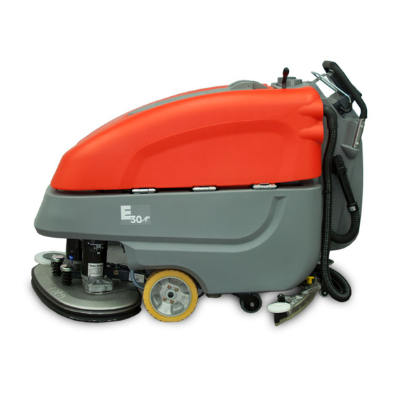
Minuteman E 28 Instruction Manual
Hide thumbs
Also See for E 28:
- User manual (42 pages) ,
- Service manual (83 pages) ,
- Instruction manual (42 pages)
Advertisement
Quick Links
Advertisement

Subscribe to Our Youtube Channel
Related Manuals for Minuteman E 28


Summary of Contents for Minuteman E 28
- Page 1 Instruction Manual E 28/30/33 (7311.44)
- Page 2 Preface Proper use...
- Page 4 Introduction ... . . 2 Safety information ..5 Technical Data ..20 Maintenance and Care ..22 First Operation .
-
Page 5: Safety Information
Safety information Safety and Warning Symbols... - Page 6 General Provisions Provisions for Operation...
- Page 7 Maintenance instructions...
- Page 8 Specific Hazards Information for Protection of Electric system Environment Battery...
- Page 9 Labels at the Machine Fig.1...
-
Page 10: First Operation
First Operation Operation Instruction Initial charging procedure Start Machine Before Putting into Operation... - Page 11 Stop Machine After Work Transporting the machine Tie-down points Fig.2...
-
Page 12: Operation
Operation Method of operation General 3.1.1 Brush Deck 3.1.2 Solution Tank Fig.3... - Page 13 3.1.3 Squeegee 3.1.5 Travel Drive 3.1.6 Batteries and Charger 3.1.7 Options 3.1.4 Recovery Tank...
- Page 14 Operating and Indicating Ele- ments 3.2.1 Operating Panel Fig.4...
- Page 15 Display (Fig. 4/1) LDS indicator (Fig. 4/4) Hourmeter (Fig. 4/7) Service indicator (Fig. 4/8) Symbol brush drive (Fig. 4/5) Battery charge indication (Fig. 4/3) Symbol suction turbine drive (Fig. 4/...
- Page 16 Drive direction control with speed control knob/bail handle (Fig. 4/16) free (Fig. 4/9) Solution dosage tip-switch (Fig. 4/ Silence Kit tip symbol (optional) (Fig. 4/10) Solution supply ON/OFF tip-switch (Fig. 4/14) Solution dosage symbol (Fig. 4/11) free (Fig. 4/15) Silence Kit tip-switch (optional) (Fig. 4/12)
- Page 17 3.2.2 At the machine Fig.5...
- Page 18 Pedal brush deck (Fig. 5/1) Power connection charger unit (Fig. 5/8) Opening of solution tank (Fig. 5/2) Pedal brush deck pressure (Fig. 5/9) Hand lever for squeegee lift-out (Fig. 5/3) Solution filter (Fig. 5/4) Recovery tank drain hose (Fig. 5/5) Solution tank drain hose (Fig.
- Page 19 Dirt hopper guiding rail (Fig. 6/1) Lever for cylindrical brush seating (Fig. 6/2) Swing aside squeegee Fig.6...
-
Page 20: Technical Data
Technical Data... - Page 21 Noise emission Vibration...
-
Page 22: Maintenance And Care
Maintenance and Care System Maintenance System Maintenance I : General System Maintenance II: System Maintenance S: System Maintenance K:... - Page 23 Maintenance Document...
- Page 24 Maintenance Schedule System Maintenance Customer Interval To be performed daily weekly...
- Page 25 System Maintenance I Interval To be performed every 125 hours of operation...
- Page 26 System Maintenance II Interval To be performed every 250 hours of operation...
- Page 27 System Maintenance S (Safety check) Interval To be performed every 500 hours of operation...
- Page 28 Battery Systems Fig.7...
- Page 29 5.4.1 Charge Batteries 5.4.2 Low Discharge Signal sender 5.4.5 Install Batteries (LDS) 5.4.3 Maintenance of Drive Batter- 5.4.6 Disposal of Batteries 5.4.4 Remove Batteries...
- Page 30 Solution Tank Fig.8...
- Page 31 5.5.1 Fill Solution Tank 5.5.3 Clean Solution Filter 5.5.2 Empty Solution Tank...
- Page 32 Recovery Tank Fig.9...
- Page 33 5.6.1 Empty Recovery Tank 5.6.2 Clean Recovery Tank 5.6.3 Clean Suction Filter...
- Page 34 Disc brush deck 5.7.1 Clean Brushes 5.7.2 Change Brushes 5.7.3 Change Deflector Roller 5.7.4 Change Sealing Strip Fig.10...
- Page 35 Cylindrical brush deck 5.8.1 Clean dirt hopper 5.8.2 Remove brushes 5.8.3 Clean brushes 5.8.4 Fit brushes 5.8.5 Change deflector roller Fig.11...
- Page 36 Squeegee 5.9.1 Cleaning the Squeegee 5.9.2 Changing the Sealing Strips Fig.12...
- Page 37 5.9.3 Adjusting the Sealing Strips Angle Adjustment Fig.13...
- Page 38 Height Adjustment Fig.14...
Need help?
Do you have a question about the E 28 and is the answer not in the manual?
Questions and answers