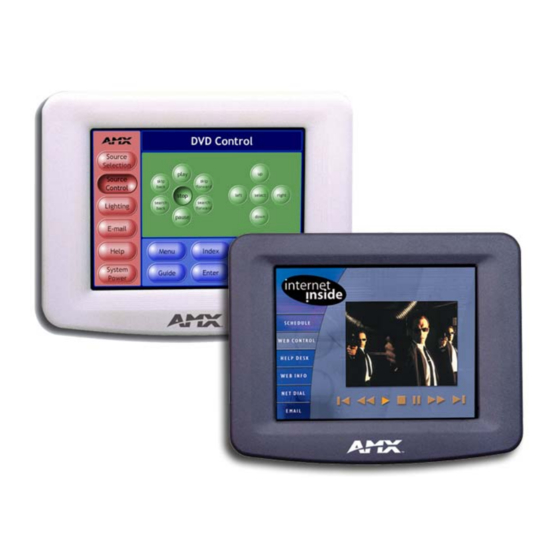
AMX AXD-CV6 Instruction Manual
6" color video
wall panel
Hide thumbs
Also See for AXD-CV6:
- Specifications (3 pages) ,
- Instruction manual (152 pages) ,
- Product catalog (118 pages)

Related Manuals for AMX AXD-CV6


Summary of Contents for AMX AXD-CV6
- Page 1 instruction manual 6" Color Video Wall Panel (Firmware version G3 or higher) Tou c h Pa n els an d A cc e ss o r ie s...
- Page 2 This warranty extends only to products purchased directly from AMX Corporation or an Authorized AMX Dealer. AMX Corporation is not liable for any damages caused by its products or for the failure of its products to perform. This includes any lost profits, lost savings, incidental damages, or consequential damages. AMX Corporation is not liable for any claim made by a third party or by an AMX Dealer for a third party.
-
Page 3: Table Of Contents
Table of Contents Table of Contents Product Information ....................1 Specifications ........................1 Cleaning the Touch Overlay....................2 Installation .........................3 Mounting Decor-style Panels .................... 3 Mounting the Decor-style panel into a pre-wall conduit box (BB-CV6) ........3 Mounting the Decor-style panel on a flat or solid surface ............4 Mounting the Decor-style panel on plasterboard (dry wall)............ - Page 4 Variable Text Send_Commands ..................38 Shorthand Variable Text Commands ................40 Button String Commands ....................43 Upgrading the Firmware ..................45 Configuration........................45 Downloading the Firmware ..................... 45 Replacing the Battery .................... 47 AXD-CV6 Battery Replacement ..................47 6” Color Video Wall Panel...
-
Page 5: Product Information
Product Information Product Information The AMX™ Color Video Wall Panel (AXD-CV6) contains a 6" (14.40 cm visible area) 256-color active-matrix liquid crystal display (LCD). The self-contained enclosure uses a microprocessor to control a wide range of multimedia equipment. The TPDesign3 touch panel design program makes it possible to create custom pages with buttons, icons, sliders, bargraphs, time displays, logos, and drawings. -
Page 6: Cleaning The Touch Overlay
• Detachable magnetic front panel bezel Installation Cutout Cutout Template for the AXD-CV6 is available as drawing number 62-5924-06 and inserted in the product packaging. This file provides 1:1 cutout dimensions for the CV6 conduit/wallbox. For replacement of the cutout, contact your AMX sales repre- sentative. -
Page 7: Installation
Installation Installation Mounting Decor-style Panels The following paragraphs describe mounting the Decor-style touch panel using the different types of available methods and surfaces. Mounting the Decor-style panel into a pre-wall conduit box (BB-CV6) The CV6 Conduit/wallbox is an optional metallic housing that is installed onto a beam in a pre-wall setting. -
Page 8: Mounting The Decor-Style Panel On A Flat Or Solid Surface
Installation 7. Verify that the panel is receiving power and functioning properly. This should be done to prevent repetition of the installation. 8. Disconnect the AXlink connector from the Central Controller until the installation of the panel is complete. 9. Connect the data and power wiring to the rear of the touch panel. 10. - Page 9 Installation Solid surface Install the #4-40 (can include a machine screws wall, podium, or into the holes other level shown below. surface) These 4 screws are removed Screw length to access or depends on the replace the installation surface. battery. - Decor faceplate B - Main AXD unit consists of...
- Page 10 Installation CUT-OUT TEMPLATE AXD-CV6 (NOT FOR USE WITH BB-CV6 CONDUIT BOX) If something happens to the template, contact DRYWALL CLIPS (2) 2" LONG SCREWS (2) your sales representative NOTE ORIENTATION - REAR CONNECTORS for another copy. TOWARDS TOP THESE 4 HOLES ARE REQUIRED...
-
Page 11: Mounting The Decor-Style Panel On Plasterboard (Dry Wall)
FIG. 8 Decor-style panel installation configuration for drywall surfaces The drywall clip set must be re-ordered from AMX if the drywall clip is bent accidentally during an installation or removed during a re-installation. 2. Cut out the install surface using the dimensions shown in FIG. 9. Be sure to cut out the two notches along the side of the CV6 to accommodate the two provided drywall expansion clips. -
Page 12: Wiring The Touch Panel
Installation 3. Thread the incoming AXlink wiring through the cutout in the wall. 4. Disconnect the AXlink connector from the Central Controller and thread the terminal end of the 4-pin AXlink cable through the circular cutout provided on the wallbox. 5. -
Page 13: Preparing Captive Wires
DB-9 RS-232 connector connector AXD-CV6 (Rear view) FIG. 11 Rear views of the AXD-CV6 wall panel Preparing captive wires You will need a wire stripper and flat-blade screwdriver to prepare and connect the captive wires. 1. Strip 0.25 inch of wire insulation off all wires. -
Page 14: Using Axlink For Data And Power
AXlink connector. Using a BNC video cable to provide video input Connect the control system’s video connector to the rear of the AXD-CV6 using a BNC cable to provide a video feed, as seen in FIG. 14. Some installations may require a 90° right-angle BNC adapter to accomodate a sharp bend in the video cable. -
Page 15: Using The (Db-9) Rs-232 Connector For Mouse Control Or Data
Female video view AXD-CV6 source connector FIG. 14 BNC cable connection from the AXD-CV6 to the video source Using the (DB-9) RS-232 connector for mouse control or data The dual-function (DB-9) RS-232 connector supports most standard serial mouse control devices and RS-232 communication protocols for PC data transmission. - Page 16 Installation 6" Color Video Wall Panel...
-
Page 17: Designing Touch Panel Pages
Designing Touch Panel Pages Designing Touch Panel Pages There are two ways to approach creating touch panel pages: TPDesign3 - Refer to the TPDesign3 Touch Panel Program (Version 3. 16) instruction manual for more information. On-board editor This document describes basic use of the on-board editor to create pages and buttons. Refer to the G3 Firmware Design and Reference instruction manual for more detailed firmware information. -
Page 18: Activating Edit Mode
Designing Touch Panel Pages General Button Categories (Cont.) Status buttons Status buttons always have a dark fill with light letters and have no functionality except to display information. Operation bars Operation bars appear in the place of the Editor bar, after selecting a button or page edit operation. - Page 19 Designing Touch Panel Pages FIG. 17 Setup page 4. Press to enable Edit mode. The button is highlighted in the Protected Setup EDITOR EDITOR page when enabled, as shown in FIG. 18. FIG. 18 Protected Setup page with the active EDITOR button 5.
-
Page 20: Setting The Device Base
Designing Touch Panel Pages Setting the Device Base Press the option, in the Protected Setup page (FIG. 18), to assign a base (starting) DEVICE BASE device address to the touch panel. 1. Enter the base address for the touch panel. The base address range is from 1 - 255. Standard device addresses begin at 128. -
Page 21: Defining On-Screen And External Button Properties
Designing Touch Panel Pages Defining On-Screen and External Button Properties External pushbuttons are configured with features similar to on-screen buttons. Their functionality can be set just as any other button on the touch panel. Use the option of the menu in the Edit bar to set button borders, page flips, PROPERTIES BUTTON button colors for channel on/off conditions, channel/variable text codes, and string/macro... -
Page 22: Setting The Variable Text Code
Designing Touch Panel Pages Setting the variable text code The variable text buttons set the device and button channel codes for the buttons. 1. Press to open the keypad and set the device number. 2. Enter 1, 2, 3, or 4 in the keypad. The source code uses device codes 1 - 4 to identify the touch panel. -
Page 23: Using Tpdesign3 To Download Bitmaps, Icons, And Fonts
Designing Touch Panel Pages 4. Go through each option and set as desired: sets the text for the button's Off and On state. TEXT OFF TEXT ON sets the icon for the button's Off and On state. ICON OFF ICON ON sets the bitmap for the button's Off and On state. -
Page 24: Adding A Bargraph Or Joystick Button
Designing Touch Panel Pages Adding a bargraph or joystick button\ Create a new button using the Add operation bar in the menu. BUTTON 1. Press in the Edit bar to open the menu. BUTTON BUTTON 2. Press in the menu to open the operation bar. -
Page 25: Programming
Programming Programming You can program the touch panel, using the commands in this section, to perform a wide variety of operations using Axcess Send_Commands and variable text commands. Use the commands described in this section to program the touch panel. Serial Commands Serial Commands are used in the AxcessX Terminal Emulator mode. - Page 26 Programming Serial Commands (Cont.) ECHO ON Syntax: Turns On charac- "ECHO ON" ter echo. Example: ECHO ON The character echo is sent back to the computer. ECHO OFF Syntax: Turns Off charac- "ECHO OFF" ter echo. Example: ECHO OFF The character echo is not sent back to the computer. GET CAL Syntax: Gets the calibra-...
-
Page 27: System Send_Commands
Programming Serial Commands (Cont.) SETUP Syntax: Puts the touch "SETUP" panel on the Example: Setup Page. SETUP Flips the touch panel to the Setup page. Syntax: Restores the cur- "VER" rent version. Example: Returns the current version of the main firmware. WORKING? Syntax: Verifies the com-... - Page 28 Programming System Send_Commands (Cont.) ADBEEP Syntax: Outputs a double "’ADBEEP’" beep even if the Example: double beep value SEND_COMMAND TP,"’ADBEEP’" is set to 0 in the Setup page. Double beeps the panel. AKEYB The keyboard string is set to null during power-up and stored until power-down. Opens the touch Syntax: panel keyboard...
- Page 29 Programming System Send_Commands (Cont.) BRIT Syntax: Adjusts brightness "’BRIT-<level>’" of display. Variable: level = 1 - 8 (1 = minimum; 8 = maximum) Example: SEND_COMMAND TP,"’BRIT-8’" Sets to highest brightness level. CALIBRATE Syntax: Starts the touch "’CALIBRATE’" panel calibration Example: sequence.
- Page 30 Programming System Send_Commands (Cont.) MOUSE Syntax: Turns on serial "’MOUSE <mouse condition>’" mouse or other Variables: touch devices. mouse condition = 00: Mouse cursor Off ® 01: Microsoft serial mouse/cursor On Example: SEND_COMMAND TP,"’MOUSE 01’" ® Turns on Microsoft compatible serial mouse. Refer to the @MOU section on page 34 for the chart describing the BIT information and definitions.
- Page 31 Programming System Send_Commands (Cont.) RESET Syntax: Cycles power on "RESET" the touch panel. Example: RESET Cycles the power on the touch panel. Once the firmware is downloaded, send this com- mand to recycle power to the panel. This command prevents the user from having to phys- ically re-cycling power on the unit.
- Page 32 TPAGEON Syntax: Activates page "’TPAGEON’" tracking. Example: SEND_COMMAND TP,’TPAGEON’ DEFINE_DEVICE TP1 = 128 (*AMX Touch Panel*) TP2 = 129 (*AMX Touch Panel*) DEFINE_VARIABLE TP1_BUFFER[100] (*Buffer for TP1*) TP2_BUFFER[100] (*Buffer for TP2*) TRASH[50] (*For Parsing Above*) DEFINE_START CREATE_BUFFER TP1,TP1_BUFFER CREATE_BUFFER TP2,TP2_BUFFER SEND_COMMAND TP1,’TPAGEON’...
-
Page 33: Video Send_Commands
Programming System Send_Commands (Cont.) ZAP! Syntax: Clears all mem- "’ZAP!’" ory; erases but- Example: tons, pages, SEND_COMMAND TP,"’ZAP!’" drawings, and symbols. Clears all memory and erases all buttons, pages, drawings, and symbols. Only use the ZAP! command to erase the saved data in the touch panel; data cannot be recovered after it is erased. - Page 34 Programming Video Send_Commands (Cont.) @VDD Syntax: Sets the video "’@VDD <ASCII settings for video detection>’" setting for auto- Variables: detection or man- ASCII detection settings = 1: Auto-detect video input ual detection of the video stan- 2: Manual set NTSC dard.
-
Page 35: Programming Numbers
Programming Programming Numbers The following information provides the programming numbers for colors, fonts, and borders. Colors can be used to set the colors on buttons, sliders, gauges, and pages. The lowest color number represents the lightest color-specific display; the highest number represents the darkest display. For example, 0 represents light red, and 5 is dark red. -
Page 36: Shorthand Send_Commands
AMX products. However, shorthand commands are smaller byte-for-byte, and are processed more efficiently. The table below lists the shorthand Send_Commands you can use with the AXD-CV6 touch panel. The shorthand command data is 1-byte, non-ASCII format except for pages, passwords, text, and bitmap names. - Page 37 Programming Shorthand Send_Commands (Cont.) @CPG This only works if the new background color is not the same as the current color. Sets the specified Syntax: page’s back- "’@CPG’,<color_number>,’<page name>’" ground color to Variables: the specified color. color number = See the Colors and Programming Numbers table on page 31. page name = 1 –...
- Page 38 Programming Shorthand Send_Commands (Cont.) @IDP Syntax: Queries the touch "’@IDP’" panel to return a Example: string with the SEND_COMMAND TP,"’@IDP’" TPDesign3 project name. The touch panel returns a string containing the TPDesign3 project name. @MOU When changing the serial touch device, you must connect the hardware before setting the device type.
- Page 39 Programming Shorthand Send_Commands (Cont.) @PPN If a page name is empty the current page is used. Activates a popup Syntax: page on a touch "’@PPN-<popup page name>;<page name>’" panel page. Variables: popup page name = popup page name page name = page name Example: SEND_COMMAND TP,"’@PPN-Laser Disc 2 Transport Control;...
-
Page 40: Color Send_Commands
Programming Shorthand Send_Commands (Cont.) @SWK Syntax: Changes the "’@SWK-<string>’" Wakeup string Variable: sent to the Con- string = alphanumeric characters troller when the touch panel is Example: activated. SEND_COMMAND TP,"’@SWK-Touch Panel Activated’" Sends Touch Panel Activated to the Central Controller. Color Send_Commands Use the color Send_Commands to set the colors for text, buttons, and pages. - Page 41 Programming Color Send_Commands (Cont.) CBOFF Syntax: Sets the OFF "’CBOFF<variable text address>-<color_number>’" feedback border Variables: color to the speci- variable text address = 1 - 255 fied color. color number = See the Colors and Programming Numbers table on page 31. Example: SEND_COMMAND TP,"’CBOFF1-72’"...
-
Page 42: Variable Text Send_Commands
Programming Color Send_Commands (Cont.) CTOFF Syntax: Sets the OFF "’CTOFF<variable text address>-<color_number>’" feedback text Variables: color to the speci- variable text address = 1 - 255 fied color. color number = See the Colors and Programming Numbers table on page 31. Example: SEND_COMMAND TP,"’CTOFF1-87’"... - Page 43 Programming Variable Text Send_Commands (Cont.) Syntax: Sets the border, "’!C’,<variable text address>,<border style>,<font font, and text in size>,’<new button text>’" one command. Variables: variable text address = 1 - 255 border style = See the Border Styles and Programming Numbers table on page 31. font size = See the Font Styles and Programming Numbers table on page 31.
-
Page 44: Shorthand Variable Text Commands
Programming Variable Text Send_Commands (Cont.) Syntax: Shorthand ver- "’!T’,<variable text address>,’<new button text>’" sion of 'TEXT' Variables: command. variable text address = 1 - 255 new button text = 1 - 60 characters Example: SEND_COMMAND TP,"’!T’,1,’VCR PLAY’" Changes the title on variable text button one to VCR PLAY. TEXT Use the | character to display text on multiple lines. - Page 45 Programming Shorthand Variable Text Commands (Cont.) @BMF This command allows you to program up to 12 attributes on one command line. Sets multiple Syntax: attributes to a but- "’@BMF’,<variable text address>,’<attribute data>’" ton, slider, or Variables: gauge. variable text address = 1 - 255 attribute data: ’%R,<left>, <top>, <right>, <bottom>’...
- Page 46 Programming Shorthand Variable Text Commands (Cont.) @FON Syntax: Sets the text font "’@FON’,<variable text address>,<font style>" on a button. Variables: variable text address = 1 - 255 font style = See the Font Styles and Programming Numbers table on page 31. Example: SEND_COMMAND TP,"'@FON',56,32"...
-
Page 47: Button String Commands
Programming Shorthand Variable Text Commands (Cont.) @TXT Use the | character to display text on multiple lines. Adds text to a but- Syntax: ton. "’@TXT’,<variable text address>,’<text>’" Variables: variable text address = 1 - 255 text = Enter button text to appear on the button. Example: SEND_COMMAND TP,"’@TXT’,2,’VCR|PLAY’"... - Page 48 Programming Button String Commands (Cont.) Syntax: Activates sleep "$SL" mode on the Example: touch panel. Activates sleep mode on the touch panel. Syntax: Sends data out "$SP"<data>"" through the serial Variables: port of the source data = Serial string command panel to a destina- tion panel.
-
Page 49: Upgrading The Firmware
RAM to flash memory, the unit will not operate at all when power returns. If you have not already installed the SoftROM program, do so by following the steps on the AMX Control Disc. - Page 50 Upgrading the Firmware Firmware can be downloaded to multiple device numbers automatically. If multiple devices are selected, the bottom half of the loading bar indicates the percentage complete for the selected devices. 7. Press F10 to exit the SoftROM program. 6"...
-
Page 51: Replacing The Battery
Once these drywall clips are separated from their screws, the drywall clip set must be re-order from AMX before the unit can be mounted to this type of surface again. Refer to FIG. 8 on page 7 for more information. - Page 52 Replacing the Battery 5. Place the touch panel facedown onto a soft cloth and begin unscrewing the four screws securing the housing to the main unit. Refer to FIG. 4 on page 5 for more information. 6. Remove the touch overlay’s ribbon cable connectors from the circuit card. 7.
- Page 53 Replacing the Battery 6" Color Video Wall Panel...
- Page 54 AMX reserves the right to alter specifications without notice at any time. brussels • dallas • los angeles • mexico city • philadelphia • shanghai • singapore • tampa • toronto* • york 3000 research drive, richardson, TX 75082 USA • 469.624.8000 • 800.222.0193 • fax 469.624.7153 • technical support 800.932.6993...
Need help?
Do you have a question about the AXD-CV6 and is the answer not in the manual?
Questions and answers