AMX AXD-MCP Instruction Manual
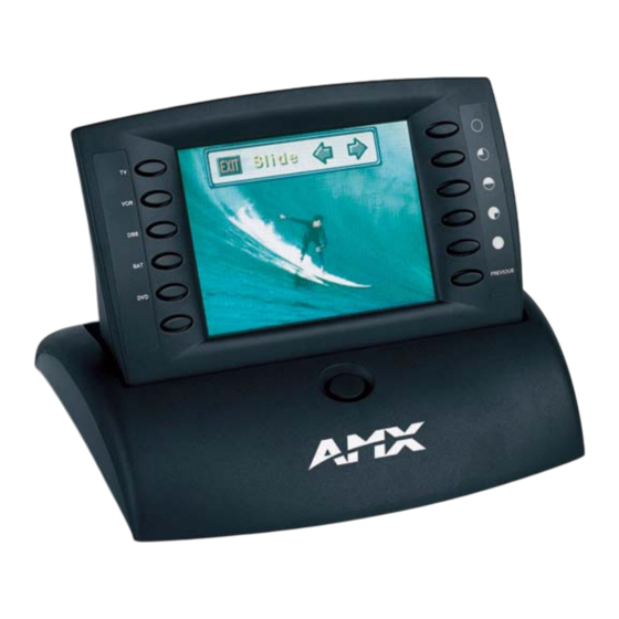
5.5" color passive mini-touch panels
Hide thumbs
Also See for AXD-MCP:
- Product catalog (118 pages) ,
- Dimensional drawing (1 page) ,
- Specifications (2 pages)

Related Manuals for AMX AXD-MCP


Summary of Contents for AMX AXD-MCP
- Page 1 instruction manual 5.5" Color Passive Mini-Touch Panels (Firmware version G3) Tou c h Pa n els an d A cc e ss o r ie s...
- Page 2 RMA number. AMX Corporation is not liable for any damages caused by its products or for the failure of its products to perform. This includes any lost profits, lost savings, incidental damages, or consequential damages. AMX Corporation is not liable for any claim made by a third party or by an AMX Dealer for a third party.
-
Page 3: Table Of Contents
Using the AXlink mini-XLR connector for data and power (AXT-MCP)........9 Using the AXlink mini-XLR connector and external 12 VDC power supply (AXT-MCP) ..9 Using AXlink for data and power (AXD-MCP and AXM-MCP)..........10 Using AXlink for data with an external 12 VDC power supply..........10 Designing Touch Panel Pages ................11... - Page 4 Button String Commands ....................42 Upgrading the Firmware ..................45 Configuration........................45 Downloading the Firmware ..................... 45 Replacing the Batteries ..................47 AXD-MCP (/PB) and AXM-MCP (/PB) Battery Replacement.......... 47 AXT-MCP (/PB) Battery Replacement ................48 5.5" Color Passive Mini-Touch Panels...
-
Page 5: Product Information
AXM-MCP/PB TiltScreen AXT-MCP AXT-MCP/PB Specifications The table below lists the AXD-MCP (/PB), AXM-MCP (/PB), and AXT-MCP (/PB) specifications. Specifications Dimensions (HWD): AXD-MCP • 5.00" x 6.98" x 2.17" (12.7 cm x 17.73 cm x 5.51 cm [low-profile Back Box]) • 4.17" x 6.98" x 2.94" (10.59 cm x 17.73 cm x 7.47 cm [CB-MTP Back Box]) AXT-MCP •... -
Page 6: Cleaning The Touch Overlay
• PSN6.5 Power supply (recommended to power the MCP) (FG423-41) • Up to 6 pushbuttons per side • 4-pin mini-XLR/cable assembly (AXD-MCP only) (64-1080) • External pushbuttons (AXD-MCP (/PB)) • UniMount Back Box (CB-MTP) (FG027-10) and faceplate bezel security plates Cleaning the Touch Overlay You should clean the touch screen overlay after each day’s use. -
Page 7: Installation
Installation Installation Mounting the Mini-Touch Panels The following paragraphs describe mounting the Decor and rack-mount touch panels. TiltScreen touch panels can be placed on any flat surface. Decor style panels with low-profile Back Boxes The touch panel must always be installed with the release slot located at the bottom. 1. -
Page 8: Installing Touch Panels And A Cb-Mtp Back Box (Solid Surfaces)
12. Reconnect the AXlink wiring to the Central Controller. The touch panel beeps when power is applied. Installing touch panels and a CB-MTP Back Box (solid surfaces) FIG. 2 shows an AXD-MCP/PB and CB-MTP UniMount Back Box for solid surfaces. CB-MTP Unimount BackBox enclosure... - Page 9 Installation FIG. 3 Decor style (AXD) and CB-MTP cutout dimensions (solid surfaces) 6. Disconnect the AXlink connector from the Central Controller. 7. Remove one or more knockouts to accommodate the wiring as required. 8. Thread the incoming AXlink wiring through the knockouts. 9.
-
Page 10: Installing Touch Panels And A Cb-Mtp Back Box (Plasterboard)
Installation Installing touch panels and a CB-MTP Back Box (plasterboard) The touch panel must always be installed with the release slot located at the bottom. FIG. 4 shows the AXD-MCP/PB and CB-MTP UniMount Back Box for plasterboard. CB-MTP Unimount Knockout... -
Page 11: Rack-Mount Panel (Axm-Mcp/Pb)
Installation FIG. 5 Decor-style (AXD) and CB-MTP cutout dimensions for plasterboard 14. Remove the backing from the adhesive tape strips; press the engraved overlay onto the faceplate. Once attached to the faceplate, the security screws cannot be replaced without removing the overlay. 15. -
Page 12: Wiring The Mini-Touch Panels
FIG. 7 illustrates the location of the rear panel AXlink connector on the panels. 4-pin (male) AXlink connector FIG. 7 AXD-MCP (/PB) and AXM-MCP (/PB) (top view) Preparing captive wires You will need a wire stripper, soldering iron, and flat-blade screwdriver to prepare and connect the captive wires. -
Page 13: Using The Axlink Mini-Xlr Connector For Data And Power (Axt-Mcp)
Installation Central Controller’s power supply. Refer to the Specifications section on page 1 for more information. Wiring Guidelines Wire Size Maximum Wiring Length 18 AWG 121.00 feet (36.88 m) 20 AWG 153.11 feet (46.67 m) 22 AWG 95.46 feet (29.10 m) 24 AWG 60.17 feet (18.34 m) If you install the touch panel farther away from the Central Controller than recommended in the... -
Page 14: Using Axlink For Data And Power (Axd-Mcp And Axm-Mcp)
Installation Using AXlink for data and power (AXD-MCP and AXM-MCP) Connect the Central Controller’s AXlink connector to the AXlink connector on the touch panel for data and 12 VDC power as shown in FIG. 10. PWR (+) PWR (+) Touch... -
Page 15: Designing Touch Panel Pages
Designing Touch Panel Pages Designing Touch Panel Pages There are two ways to approach creating touch panel pages: TPDesign3 - Refer to the TPDesign3 Touch Panel Program (Version 3. 16) instruction manual for more information. On-board editor This section describes the basics of using the on-board editor to create pages and buttons. For more information, refer to the G3 Firmware Design and Reference instruction manual. -
Page 16: Activating Edit Mode
Designing Touch Panel Pages General Button Categories (Cont.) Status buttons Status buttons always have a dark fill with light letters and have no functionality except to display information. Operation bars Operation bars appear in the place of the Editor bar, after selecting a button or page edit operation. - Page 17 CCFL tube, which runs around the edge. AMX has increased the range of the contrast adjustment to allow for this nature of the panel.
-
Page 18: Setting The Device Base
Designing Touch Panel Pages Edit bar FIG. 15 Main page with Edit bar Setting the Device Base Press the option, in the Protected Setup page (FIG. 14), to assign a base (starting) DEVICE BASE device address to the touch panel. 1. -
Page 19: Adding A Button
Designing Touch Panel Pages Adding a Button To add a button to the current page: 1. Press on the Edit bar to open the menu. BUTTON BUTTON 2. Press to open the operation bar. On the LCD screen, touch and drag to ADD BUTTON create a button. -
Page 20: Setting The Variable Text Code
Designing Touch Panel Pages 2. Enter 1, 2, 3, or 4 in the keypad. The programming software uses device codes 1 - 4 to identify the touch panel. Refer to the G3 Firmware Design and Reference instruction manual for more information. -
Page 21: Setting The Button Colors For Channel-Off Conditions
Designing Touch Panel Pages Setting the button colors for channel-off conditions 1. Press any button to open the Button Properties page. 2. Press under in the Button Properties page. The color palette appears. BORDER CHANNEL OFF Select a color to set as the border. 3. -
Page 22: Creating A Bargraph And Joystick
Designing Touch Panel Pages 6. In the What To Send area, select one or more of the available options (All Bitmaps, All Icons, All Fonts). 7. Select the mode of communication with the touch panel (RS-232 and AXlink). Confirm that the correct panel is selected by verifying the ID values with the Base Address assigned to the touch panel in the Protected Setup page. - Page 23 Designing Touch Panel Pages 4. Press to open a keypad and set the level number assigned to the device. 5. Enter a number 1 – 8. Each device can have from 1 – 8 levels except joysticks, where the range is 1 –...
- Page 24 Designing Touch Panel Pages 5.5" Color Passive Mini-Touch Panels...
-
Page 25: Programming
Programming Programming You can program the touch panel, using the commands in this section, to perform a wide variety of operations using Axcess Send_Commands and variable text commands. Use the commands described in this section to program the touch panel. Serial Commands Serial Commands are used in the AxcessX Terminal Emulator Mode. - Page 26 Programming Serial Commands (Cont.) ECHO OFF Syntax: Turns Off charac- "ECHO OFF" ter echo. Example: ECHO OFF The character echo is not sent back to the computer. GET CAL Syntax: Gets the calibra- "GET CAL" tion variables. Example: GET CAL Gets the calibration variables on the touch panel.
-
Page 27: System Send_Commands
Programming Serial Commands (Cont.) SETUP Syntax: Puts the touch "SETUP" panel on the Example: Setup Page. SETUP Flips the touch panel to the Setup page. Syntax: Restores the cur- "VER" rent version. Example: Returns the current version of the main firmware. WORKING? Syntax: Verifies the com-... - Page 28 Programming System Send_Commands (Cont.) The entered number is not valid if there is no WAV-PK connected to the AXT panels. Sets the power Syntax: time-out for "’$ST <number in minutes>’" TiltScreen pan- Variable: els. The command is followed by 1, 2, number in minutes = 1 - 120 or 3 ASCII digits.
- Page 29 Programming System Send_Commands (Cont.) BAUD The baud rate can also be set in the Protected Setup page’s BAUD level indicator. Sets the program Syntax: port baud rate. "’BAUD <baud rate>’" Variable: baud rate = 38400, 19200, 9600, 4800, 2400, 1200, 600, and 300 Example: SEND_COMMAND TP,"’BAUD 38400’"...
- Page 30 Programming System Send_Commands (Cont.) CLOCK Syntax: Sets the time and "’CLOCK <mm-dd-yy> <hh:mm:ss>’" date. Variables: mm = 01 - 12, dd = 01 - 31, yy = 00 - 99 hh = 00 - 23, mm = 00 - 59, ss = 00 - 59 Example: SEND_COMMAND TP,"’CLOCK 02-08-98 19:16:00’"...
- Page 31 Programming System Send_Commands (Cont.) PAGE Syntax: Flips to a page "’PAGE-<page name>’" with a specified Variable: page name. page name = 1 - 50 ASCII characters Example: SEND_COMMAND TP,"’PAGE-MAIN PAGE’" Flips the touch panel to the page named MAIN PAGE. PKEYP Syntax: Displays aster-...
- Page 32 Programming System Send_Commands (Cont.) SETUP Syntax: Goes to the Setup "’SETUP’" page. Example: SEND_COMMAND TP,"’SETUP’" Flips the touch panel to the Setup page. SLEEP Syntax: Forces the touch "’SLEEP’" panel to screen Example: saver mode. SEND_COMMAND TP,"’SLEEP’" Activates the screen saver mode. TPAGEOFF Syntax: Deactivates page...
- Page 33 TPAGEON Syntax: Activates page "’TPAGEON’" tracking. Example: SEND_COMMAND TP,’TPAGEON’ DEFINE_DEVICE TP1 = 128 (*AMX Touch Panel*) TP2 = 129 (*AMX Touch Panel*) DEFINE_VARIABLE TP1_BUFFER[100] (*Buffer for TP1*) TP2_BUFFER[100] (*Buffer for TP2*) TRASH[50] (*For Parsing Above*) DEFINE_START CREATE_BUFFER TP1,TP1_BUFFER CREATE_BUFFER TP2,TP2_BUFFER...
-
Page 34: Programming Numbers
Programming Programming Numbers The following information provides the programming numbers for colors, fonts, and borders. Colors can be used to set the colors on buttons, sliders, gauges, and pages. The lowest color number represents the lightest color-specific display; the highest number represents the darkest display. For example, 0 represents light red, and 5 is dark red. -
Page 35: Shorthand Send_Commands
Shorthand Send_Commands The shorthand commands operate control equipment just like standard Send_Commands still used in a wide variety of AMX products. However, shorthand commands are smaller byte-for-byte, and are processed more efficiently. The table below lists the shorthand Send_Commands you can use with the MCP touch panels. The shorthand command data is 1-byte, non-ASCII format except for pages, passwords, text, and bitmap names. - Page 36 Programming Shorthand Send_Commands (Cont.) @CPG This only works if the new background color is not the same as the current color. Sets the page with Syntax: specified page "’@CPG’,<color_number>,’<page name>’" name back- Variables: ground color to the specified color number = See the Colors and Programming Numbers table on page 30. color.
- Page 37 Programming Shorthand Send_Commands (Cont.) @IDP Syntax: Queries the touch "’@IDP’" panel to return a Example: string with the SEND_COMMAND TP,"’@IDP’" TPDesign3 project name. The touch panel returns a string containing the TPDesign3 project name. @MOU When changing the serial touch device, you must connect the hardware before setting the device type.
- Page 38 Programming Shorthand Send_Commands (Cont.) @PPN If a page name is empty, the current page is used. Activates a popup Syntax: page on a touch "’@PPN-<popup page name>;<page name>’" panel page. Variables: popup page name = popup page name page name = page name Example: SEND_COMMAND TP,"’@PPN-Laser Disc 2 Transport Control;...
-
Page 39: Color Send_Commands
Programming Shorthand Send_Commands (Cont.) @SWK Syntax: Changes the "’@SWK-<string>’" Wakeup string Variable: sent to the Con- string = alphanumeric characters troller when the touch panel is Example: activated. SEND_COMMAND TP,"’@SWK-Touch Panel Activated’" Sends Touch Panel Activated to the Central Controller. Color Send_Commands Use the color Send_Commands to set the colors for text, buttons, and pages. - Page 40 Programming Color Send_Commands (Cont.) CBON Syntax: Sets the ON feed- "’CBON<variable text address>-<color_number>’" back border color Variables: to the specified variable text address = 1 - 255 color. color number = See the Colors and Programming Numbers table on page 30. Example: SEND_COMMAND TP,"’CBON1-48’"...
-
Page 41: Variable Text Send_Commands
Programming Color Send_Commands (Cont.) CTON Syntax: Sets the ON feed- "’CTON<variable text address>-<color_number>’" back text color to Variables: the specified variable text address = 1 - 255 color. color number = See the Colors and Programming Numbers table on page 30. Example: SEND_COMMAND TP,"’CTON1-72’"... - Page 42 Programming Variable Text Send_Commands (Cont.) Syntax: Sets the border, "’!C’,<variable text address>,<border style>,<font font, and text in size>,’<new button text>’" one command. Variables: variable text address = 1 - 255 border style = See the Border Styles and Programming Numbers table on page 30. font size = See the Font Styles and Programming Numbers table on page 30.
-
Page 43: Shorthand Variable Text Commands
Programming Variable Text Send_Commands (Cont.) ICON Syntax: "’ICON<variable text address>-<border style>’" Changes the border style of a Variables: specific button. variable text address = 1 - 255 border style = See the Border Styles and Programming Numbers table on page 30. Example: SEND_COMMAND TP,"’ICON25-6’"... - Page 44 Programming Shorthand Variable Text Commands (Cont.) @BMF This command allows you to program up to 12 attributes on one command line. Sets multiple Syntax: attributes to a but- "’@BMF’,<variable text address>,’<attribute data>’" ton, slider, or Variables: gauge. variable text address = 1 - 255 attribute data: ’%R,<left>, <top>, <right>, <bottom>’...
- Page 45 Programming Shorthand Variable Text Commands (Cont.) @ENA Syntax: Enables/disables "’@ENA’,<variable text address>,<disable button on/off>" buttons based on Variables: the variable text variable text address = 1 – 255 channel. disable button on/off= 1 : button disabled 0 : button enabled Example: SEND_COMMAND TP,"’@ENA’,128,1"...
-
Page 46: Button String Commands
Programming Shorthand Variable Text Commands (Cont.) @SHO Syntax: Sets a specific "’@SHO’,<variable text address>,<button on/off>" button to on or off. Variables: variable text address = 1 - 255 button on/off= 0 : button Off 1 : button On Example: SEND_COMMAND TP,"’@SHO’,128,0" Sets button 128 off. - Page 47 Programming Button String Commands (Cont.) Syntax: Sets the group ID "$ID,<group ID>" number. Variable: group ID = 0 (Off) - 15 Example: $ID 15 Sets the Group ID to 15. Syntax: Sends a serial "$SC <device offset>,"’<send_command>,<variable port text #>,<data>’"" send_command Variables: within a panel, as...
- Page 48 Programming Button String Commands (Cont.) WORKING? Responding touch panels tell the sending touch panel to change its Main page to the color white. Verifies the com- munication Syntax: between touch "WORKING?" panels through Example: the use of the on- panel editor. •...
-
Page 49: Upgrading The Firmware
RAM to flash memory, the unit will not operate at all when power returns. If you have not already installed the SoftROM program, do so by following the steps on the AMX Control Disc. - Page 50 Upgrading the Firmware Firmware can be downloaded to multiple device numbers automatically. If multiple devices are selected, the bottom half of the loading bar indicates the percentage complete for the selected devices. 7. Press F10 to exit the SoftROM program. 5.5"...
-
Page 51: Replacing The Batteries
Phillips screwdriver and a non-conducting flat-blade tool to slip under the battery to pry it up and out of the socket. AXD-MCP (/PB) and AXM-MCP (/PB) Battery Replacement To remove the lithium batteries from the touch panel: 1. -
Page 52: Axt-Mcp (/Pb) Battery Replacement
Replacing the Batteries AXT-MCP (/PB) Battery Replacement Remove the lithium batteries from the AXT-MCP (/PB): 1. Discharge the static electricity from your body by touching a grounded metal object. 2. Remove the 2-pin power connector from the rear side of the panel. If you are using power via AXlink, remove the AXlink connector. - Page 53 Replacing the Batteries 5.5" Color Passive Mini-Touch Panels...
- Page 54 ATLANTA • BOSTON • CHICAGO • CLEVELAND • DALLAS • DENVER • INDIANAPOLIS • LOS ANGELES • MINNEAPOLIS • PHILADELPHIA • PHOENIX • PORTLAND • SPOKANE • TAMPA 3000 RESEARCH DRIVE, RICHARDSON, TX 75082 USA • 800.222.0193 • 469.624.8000 • 469-624-7153 fax • 800.932.6993 technical support • www.amx.com...
Need help?
Do you have a question about the AXD-MCP and is the answer not in the manual?
Questions and answers