Table of Contents
Advertisement
Quick Links
Advertisement
Table of Contents

Related Manuals for Asus P5RD2-VM


Summary of Contents for Asus P5RD2-VM
- Page 1 P5RD2-VM...
- Page 2 Product warranty or service will not be extended if: (1) the product is repaired, modified or altered, unless such repair, modification of alteration is authorized in writing by ASUS; or (2) the serial number of the product is defaced or missing.
-
Page 3: Table Of Contents
Contents Notices ... vi Safety information ... vii About this guide ...viii Typography ... ix P5RD2-VM specifications summary ... x Chapter 1: Product introduction Welcome! ... 1-2 Package contents ... 1-2 Special features ... 1-2 1.3.1 Product highlights ... 1-2 1.3.2... - Page 4 Creating a bootable floppy disk ... 2-2 2.1.2 ASUS EZ Flash utility ... 2-3 2.1.3 AFUDOS utility ... 2-4 2.1.4 ASUS CrashFree BIOS 2 utility ... 2-6 2.1.5 ASUS Update utility ... 2-8 BIOS setup program ... 2-11 2.2.1 BIOS menu screen ... 2-12 2.2.2...
- Page 5 Drivers menu ... 3-3 3.2.3 Utilities menu ... 3-4 3.2.4 Make Disk ... 3-5 3.2.5 Manual menu ... 3-6 3.2.6 ASUS Contact information ... 3-6 Appendix: CPU features Intel EM64T ... A-2 ® Using the Intel ® Enhanced Intel SpeedStep A.2.1...
-
Page 6: Federal Communications Commission Statement
Notices Federal Communications Commission Statement This device complies with Part 15 of the FCC Rules. Operation is subject to the following two conditions: • This device may not cause harmful interference, and • This device must accept any interference received including interference that may cause undesired operation. -
Page 7: Electrical Safety
Safety information Electrical safety • To prevent electrical shock hazard, disconnect the power cable from the electrical outlet before relocating the system. • When adding or removing devices to or from the system, ensure that the power cables for the devices are unplugged before the signal cables are connected. -
Page 8: Where To Find More Information
Refer to the following sources for additional information and for product and software updates. ASUS websites The ASUS website provides updated information on ASUS hardware and software products. Refer to the ASUS contact information. Optional documentation Your product package may include optional documentation, such as warranty flyers, that may have been added by your dealer. -
Page 9: Conventions Used In This Guide
Conventions used in this guide To make sure that you perform certain tasks properly, take note of the following symbols used throughout this manual. DANGER/WARNING: Information to prevent injury to yourself when trying to complete a task. CAUTION: Information to prevent damage to the components when trying to complete a task. -
Page 10: P5Rd2-Vm Specifications Summary
P5RD2-VM specifications summary Chipset Front Side Bus Memory Expansion slots Storage Audio Rear panel LGA775 socket for Intel Pentium ® or Intel Celeron processors ® ® Compatible with Intel PCG 05B/05A processors ® Supports Enhanced Intel SpeedStep Supports Intel Hyper-Threading Technology ®... - Page 11 Micro-ATX form factor: 9.6 in x 8.6 in Support CD Device drivers contents ASUS PC Probe II ASUS Live Update utility Anti-virus software (OEM version) *Specifications are subject to change without notice. SM BIOS 2.3, ASUS EZ Flash Chassis Intrussion...
- Page 13 This chapter describes the motherboard features and the new technologies it supports. Product introduction ASUS P5RD2-VM...
-
Page 14: Welcome
T h a n k y o u f o r b u y i n g a n A S U S The motherboard delivers a host of new features and latest technologies, making it another standout in the long line of ASUS quality motherboards! Before you start installing the motherboard, and hardware devices on it, check the items in your package with the list below. - Page 15 Serial ATA interfaces and the ULI M1575 chipset. The SATA 3Gb/s specification provides twice the bandwidth of the current Serial ATA products. Additionally, Serial ATA allows thinner, more flexible cables with lower pin count, and reduced voltage requirement. See pages 1-28. ASUS P5RD2-VM...
-
Page 16: Innovative Asus Features
2-33. ASUS EZ Flash BIOS With the ASUS EZ Flash, you can easily update the system BIOS even before loading the operating system. No need to use a DOS-based utility or boot from a floppy disk. See page 2-3 for details. -
Page 17: Onboard Led
This is a reminder that you should shut down the system and unplug the power cable before removing or plugging in any motherboard component. The illustration below shows the location of the onboard LED. P5RD2-VM ® P5RD2-VM Onboard LED ASUS P5RD2-VM SB_PWR Standby Powered Power... -
Page 18: Motherboard Overview
Place eight (6) screws into the holes indicated by circles to secure the motherboard to the chassis. Do not overtighten the screws! Doing so can damage the motherboard. Place this side towards the rear of the chassis P5RD2-VM ® Chapter 1: Product introduction... -
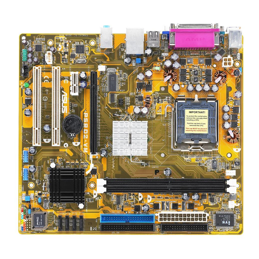
Page 19: Motherboard Layout
B: Keyboard COM1 ATX12V VGA1 USB12 LAN_USB34 Top:Line In CHA_FAN1 Center:Line Out Below:Mic In RTL8111B PCIEX1_1 SPDIF_OUT AD1986A AAFP SB_PWR ASUS P5RD2-VM 24.3cm (9.6in) CPU_FAN LGA775 RC410 TV_C PCIEX16 P5RD2-VM CR2032 3V Lithium Cell CMOS Power ® PCI1 PCI2 USB56 USB78... -
Page 20: Central Processing Unit (Cpu)
Contact your retailer immediately if the PnP cap is missing, or if you see any damage to the PnP cap/socket pins/motherboard components. ASUS will shoulder the cost of repair only if the damage is shipment/ transit-related. •... - Page 21 The socket alignment key should fit into the CPU notch. ASUS P5RD2-VM This side of the cam box should face you. Load plate Alignment key Gold triangle mark...
- Page 22 Close the load plate (A), then push the load lever (B) until it snaps into the retention tab. The CPU fits in only one correct orientation. DO NOT force the CPU into the socket to prevent bending the connectors on the socket and damaging the CPU! The motherboard supports Intel LGA775 processors with the Intel...
-
Page 23: Installling The Cpu Heatsink And Fan
CPU, making sure that the four fasteners match the holes on the motherboard. Motherboard hole Make sure each fastener is oriented as shown, with the narrow groove directed outward. ASUS P5RD2-VM Pentium ® ® Pentium 4 LGA775 heatsink and fan assembly comes in ®... - Page 24 Push down two fasteners at a time in a diagonal sequence to secure the heatsink and fan assembly in place. When the fan and heatsink assembly is in place, connect the CPU fan cable to the connector on the motherboard labeled CPU_FAN. Do not forget to connect the CPU fan connector! Hardware monitoring errors can occur if you fail to plug this connector.
-
Page 25: Uninstalling The Cpu Heatsink And Fan
To uninstall the CPU heatsink and fan: Disconnect the CPU fan cable from the connector on the motherboard. Rotate each fastener counterclockwise. Pull up two fasteners at a time in a diagonal sequence to disengage the heatsink and fan assembly from the motherboard. ASUS P5RD2-VM 1-13... - Page 26 Remove the heatsink and fan assembly from the motherboard. Rotate each fastener clockwise to reset the orientation. The narrow end of the groove should point outward after resetting. (The photo shows the groove shaded for emphasis.) 1-14 Narrow end of the groove Chapter 1: Product introduction...
-
Page 27: Ddr2 Qualified Vendors List
DDR DIMM socket. The following figure illustrates the location of the sockets: P5RD2-VM ® P5RD2-VM 240-pin DDR DIMM Sockets 1.7.2 Memory configurations You may install 256 MB, 512 MB, and 1 GB unbuffered non-ECC DDR2 DIMMs into the DIMM sockets using the memory configurations in this section. -
Page 28: Ddr Qualified Vendors List
DDR Qualified Vendors List The following table lists the memory modules that have been tested and qualified for use with this motherboard. Visit the ASUS website (www.asus. com) for the latest DDR2 DIMM modules for this motherboard. DDR2 667 Qualified Vendors List... - Page 29 A : Supports one module inserted in any slot as Single-channel memory configuration B : Supports one pair of modules inserted into eithor the blue slots or the black slots as one pair of Dual-channel memory configuration ASUS P5RD2-VM Brand Side(s)
-
Page 30: Installing A Dimm
1.7.4 Installing a DIMM Unplug the power supply before adding or removing DIMMs or other system components. Failure to do so can cause severe damage to both the motherboard and the components. Unlock a DIMM socket by pressing the retaining clips outward. -
Page 31: Expansion Slots
Turn on the system and change the necessary BIOS settings, if any. See Chapter 2 for information on BIOS setup. Assign an IRQ to the card. Refer to the tables on the next page. Install the software drivers for the expansion card. ASUS P5RD2-VM 1-19... -
Page 32: Interrupt Assignments
1.8.3 Interrupt assignments Standard interrupt assignments Standard Function System Timer Keyboard Controller Re-direct to IRQ#9 Communications Port (COM1)* IRQ holder for PCI steering* Floppy Disk Controller Printer Port (LPT1)* System CMOS/Real Time Clock IRQ holder for PCI steering* IRQ holder for PCI steering* IRQ holder for PCI steering* PS/2 Compatible Mouse Port* Numeric Data Processor... -
Page 33: Pci Slots
1.8.6 PCI Express x1 This motherboard supports PCI Express x1 network cards, SCSI cards and other cards that comply with the PCI Express specifications. The figure shows a network card installed on the PCI Express x1 slot. ASUS P5RD2-VM 1-21... -
Page 34: Clear Rtc Ram
Removing the cap will cause system boot failure! P5RD2-VM ® P5RD2-VM Clear RTC RAM You do not need to clear the RTC when the system hangs due to overclocking. For system failure due to overclocking, use the C.P.R. (CPU Parameter Recall) feature. -
Page 35: Usb Device Wake-Up
The USBPWR56 and USBPWR78 jumpers are for the internal USB connectors that you can connect to additional USB ports. P5RD2-VM ® P5RD2-VM USB Device Wake-Up • The USB device wake-up feature requires a power supply that can provide 500mA on the +5VSB lead for each USB port; otherwise, the system would not power up. -
Page 36: Keyboard Power (3-Pin Kbpwr)
(the default is the Space Bar). This feature requires an ATX power supply that can supply at least 1A on the +5VSB lead, and a corresponding setting in the BIOS. KBPWR +5VSB (Default) P5RD2-VM ® P5RD2-VM Keyboard Power Setting 1-24 Chapter 1: Product introduction... -
Page 37: Lan Port Led Indications
USB 2.0 ports 3 and 4. These two 4-pin Universal Serial Bus (USB) ports are available for connecting USB 2.0 devices. Refer to the audio configuration table below for the function of the audio ports in 2, 4, or 6-channel configuration. ASUS P5RD2-VM SPEED LED Status Description... -
Page 38: 1.10.2 Internal Connectors
floppy disk drive. Pin 5 on the connector is removed to prevent incorrect cable connection when using an FDD cable with a covered Pin 5. P5RD2-VM ® P5RD2-VM Floppy Disk Drive Connector 1-26 Headset 4-channel 2-channel... - Page 39 IDE cable. • Use the 80-conductor IDE cable for Ultra DMA 100/66 IDE devices. P5RD2-VM ® P5RD2-VM IDE Connectors ASUS P5RD2-VM NOTE: Orient the red markings (usually zigzag) on the IDE ribbon cable to PIN 1.
-
Page 40: Serial Ata Connectors
This connector is for the S/PDIF audio module to allow digital sound output. Connect one end of the S/PDIF audio cable to this connector and the other end to the S/PDIF module. P5RD2-VM ® P5RD2-VM Digital Audio Connector The S/PDIF out module is purchased separately. 1-28 SATA4 SATA3... -
Page 41: Cpu And Chassis Fan Connectors
By default, the pins labeled “Chassis Signal” and “Ground” are shorted with a jumper cap. Remove the jumper caps only when you intend to use the chassis intrusion detection feature. P5RD2-VM ® P5RD2-VM Chassis Intrusion Connector ASUS P5RD2-VM CHA_FAN2 CPU_FAN CPU FAN PWM... - Page 42 • Make sure that your power supply unit (PSU) can provide at least the minimum power required by your system. P5RD2-VM ® P5RD2-VM ATX Power Connectors 1-30 ATX12V EATXPWR +12V DC +12V DC +3 Volts...
-
Page 43: Internal Audio Connectors
USB 2.0 specification that supports up to 480 Mbps connection speed. P5RD2-VM ® P5RD2-VM USB 2.0 Connectors Internal audio connectors (4-pin CD [black], 4-pin AUX [white]) These connectors allow you to receive stereo audio input from sound sources such as a CD-ROM, TV tuner, or MPEG card. -
Page 44: Front Panel Audio Connector (10-1 Pin Aafp)
HD Audio or legacy ACʼ97 audio standard. P5RD2-VM ® P5RD2-VM Analog Front Panel Connector It is recommended that you connect a high-definition front panel audio module to this connector to avail of the motherboardʼs high-definition audio capability. -
Page 45: System Panel Connector
12. System panel connector (10-1 pin F_PANEL) This connector supports several chassis-mounted functions. P5RD2-VM ® P5RD2-VM System Panel Connector The sytem panel connector is color-coded for easy connection. Refer to the connector description below for details. • System power LED (Green 3-pin PLED) This 3-pin connector is for the system power LED. - Page 46 1-34 Chapter 1: Product introduction...
-
Page 47: Chapter 2: Bios Setup
This chapter tells how to change the system settings through the BIOS Setup menus. Detailed descriptions of the BIOS parameters are also provided. BIOS setup ASUS P5RD2-VM... -
Page 48: Managing And Updating Your Bios
The following utilities allow you to manage and update the motherboard Basic Input/Output System (BIOS) setup. ASUS AFUDOS (Updates the BIOS in DOS mode using a bootable floppy disk.) ASUS EZ Flash (Updates the BIOS using a floppy disk during POST.) ASUS CrashFree BIOS 2 (Updates the BIOS using a bootable floppy... -
Page 49: Asus Ez Flash Utility
2.1.2 ASUS EZ Flash utility The ASUS EZ Flash feature allows you to update the BIOS without having to go through the long process of booting from a floppy disk and using a DOS-based utility. The EZ Flash utility is built-in the BIOS chip so it is accessible by pressing <Alt>... -
Page 50: Afudos Utility
2.1.3 AFUDOS utility The AFUDOS utility allows you to update the BIOS file in DOS environment using a bootable floppy disk with the updated BIOS file. This utility also allows you to copy the current BIOS file that you can use as backup when the BIOS fails or gets corrupted during the updating process. -
Page 51: Updating The Bios File
Updating the BIOS file To update the BIOS file using the AFUDOS utility: Visit the ASUS website (www.asus.com) and download the latest BIOS file for the motherboard. Save the BIOS file to a bootable floppy disk. Write the BIOS filename on a piece of paper. You need to type the exact BIOS filename at the DOS prompt. -
Page 52: Asus Crashfree Bios 2 Utility
2.1.4 ASUS CrashFree BIOS 2 utility The ASUS CrashFree BIOS 2 is an auto recovery tool that allows you to restore the BIOS file when it fails or gets corrupted during the updating process. You can update a corrupted BIOS file using the motherboard support CD or the floppy disk that contains the updated BIOS file. -
Page 53: Recovering The Bios From The Support Cd
Restart the system after the utility completes the updating process. The recovered BIOS may not be the latest BIOS version for this motherboard. Visit the ASUS website (www.asus.com) to download the latest BIOS file. ASUS P5RD2-VM... -
Page 54: Asus Update Utility
2.1.5 ASUS Update utility The ASUS Update is a utility that allows you to manage, save, and update the motherboard BIOS in Windows allows you to: • Save the current BIOS file • Download the latest BIOS file from the Internet •... -
Page 55: Updating The Bios Through The Internet
Updating the BIOS through the Internet To update the BIOS through the Internet: Launch the ASUS Update utility from the Windows Start > Programs > ASUS > ASUSUpdate > ASUSUpdate. The ASUS Update main window appears. Select Update BIOS from... -
Page 56: Updating The Bios Through A Bios File
Updating the BIOS through a BIOS file To update the BIOS through a BIOS file: Launch the ASUS Update utility from the Windows clicking Start > Programs > ASUS > ASUSUpdate > ASUSUpdate. The ASUS Update main window appears. Select Update BIOS from a file option from the drop-down menu, then click Next. -
Page 57: Bios Setup Program
The BIOS setup screens shown in this section are for reference purposes only, and may not exactly match what you see on your screen. • Visit the ASUS website (www.asus.com) to download the latest BIOS file for this motherboard and . ASUS P5RD2-VM 2-11... -
Page 58: Bios Menu Screen
2.2.1 BIOS menu screen Menu items Menu bar System Time System Date Legacy Diskette A Primary IDE Master Primary IDE Slave Secondary IDE Master Secondary IDE Slave Third IDE Master Third IDE Slave Fourth IDE Master Fourth IDE Slave System Information Boot delay time Sub-menu items 2.2.2... -
Page 59: Menu Items
2.2.9 General help At the top right corner of the menu screen is a brief description of the selected item. ASUS P5RD2-VM System Time [11:10:19] Use [ENTER], [TAB] System Date [Thu 03/27/2003] or [SHIFT-TAB] to Legacy Diskette A [1.44M, 3.5 in]... -
Page 60: Main Menu
Main menu When you enter the BIOS Setup program, the Main menu screen appears, giving you an overview of the basic system information. Refer to section “2.2.1 BIOS menu screen” for information on the menu screen items and how to navigate through them. System Time System Date Legacy Diskette A... -
Page 61: Primary, Third And Fourth Ide Master/Slave
When set to [Disabled], the data transfer from and to the device occurs one sector at a time. Configuration options: [Disabled] [Auto] ASUS P5RD2-VM [Auto] [Auto] [Auto]... -
Page 62: 32Bit Data Transfer [Enabled]
PIO Mode [Auto] Selects the PIO mode. Configuration options: [Auto] [0] [1] [2] [3] [4] DMA Mode [Auto] Selects the DMA mode. Configuration options: [Auto] [SWDMA0] [SWDMA1] [SWDMA2] [MWDMA0] [MWDMA1] [MWDMA2] [UDMA0] [UDMA1] [UDMA2] [UDMA3] [UDMA4] [UDMA5] SMART Monitoring [Auto] Sets the Smart Monitoring, Analysis, and Reporting Technology. -
Page 63: Jumperfree Configuration
USB 2.0 Controller Mode BIOS EHCI Hand-Off The Module Version and USB Devices Enabled items show the auto-detected values. If no USB device is detected, the item shows None. ASUS P5RD2-VM Configure CPU. Enter Go to Sub-screen [USB OHCI + EHCI] [Auto]... -
Page 64: Legacy Usb Support [Auto]
USB Controller [USB OHCI + EHCI] Configuration options: [Disabled] [USB OHCI] [USB OHCI + EHCI] Legacy USB Support [Auto] Allows you to enable or disable support for USB devices on legacy operating systems (OS). Setting to Auto allows the system to detect the presence of USB devices at startup. -
Page 65: Jumperfree Configuration
400. Refer to the table below for the correct Front Side Bus and CPU External Frequency settings. FSB/CPU External Frequency Synchronization Front Side Bus FSB 1066 FSB 800 FSB 533 ASUS P5RD2-VM Select the target CPU frequency, and the [Auto] relevant parameters [Manual] will be auto-adjusted. - Page 66 Memory Clock Mode [Manual] Allows you to synchronize the Memory frequency with the CPU frequency. Configuration options: [Auto] [Manual] Refer to the DDR2 documentation before adjusting the memory voltage. Setting a very high memory voltage may damage the memory module(s)! OverClock Memory Clock [XXX] Allows you to set the Memory frequency.
-
Page 67: Cpu Configuration
Max CPUID Value Limit [Disabled] Enable this item to boot legacy operating systems that cannot support CPUs with extended CPUID functions. Configuration options: [Disabled] [Enabled] ASUS P5RD2-VM Sets the ratio between CPU Core Clock and the FSB Frequency. NOTE: If an invalid... - Page 68 Execute Disable Function [Disabled] Allows you to enable or disable the no execution on page protection technology. When enabled, the system forces the XD feature flag to always return to zero. Configuration options: [Disabled] [Enabled] Enhanced C1 Control [Auto] When set to [Auto], the BIOS automatically checks CPU capability to enable the C1E support.
-
Page 69: Chipset
Allow you to set the Device that used to display video. Configuration options: [Auto] [CRT Only] [TV Only] TV Standard [NTSC] This option allow you to set the TV Standard. Configuration options: [NTSC] [PAL] ASUS P5RD2-VM [PEG/IGD] :274MHz [Disabled] [64MB]... -
Page 70: Configure Dram Timing By Spd [Enabled]
Advanced NB If you select the option of Advanced NB, the following options will appearred. Configure DRAM Timing by SPD DRAM CAS Select DRAM tRP Select DRAM tRCD Select DRAM tRAS Select Refresh Rate Select Configure DRAM Timing by SPD [Enabled] When this item is enabled, the DRAM timing parameters are set according to the DRAM SPD (Serial Presence Detect). -
Page 71: Southbridge Configuration
Onboard LAN Boot ROM [Disabled] Allows you to enable or disable the option ROM in the onboard LAN controller. This item appears only when the Onboard LAN item is set to Enabled. Configuration options: [Disabled] [Enabled] ASUS P5RD2-VM [Enabled] [Disabled] [Emulated PATA mode]... -
Page 72: Onboard Devices Configuration
2.4.5 Onboard Devices Configuration Configure ITE8712 Super IO Chipset Serial Port1 Address Parallel Port Address Parallel Port Mode EPP Version ECP Mode DMA Channel Parallel Port IRQ Serial Port1 Address [3F8/IRQ4] Allows you to select the Serial Port1 base address. Configuration options: [Disabled] [3F8/IRQ4] [2F8/IRQ3] [3E8/IRQ4] [2E8/IRQ3] Parallel Port Address [378]... -
Page 73: Pci Pnp
Palette Snooping [Disabled] When set to [Enabled], the pallete snooping feature informs the PCI devices that an ISA graphics device is installed in the system so that the latter can function correctly. Configuration options: [Disabled] [Enabled] ASUS P5RD2-VM [No] [64] [Yes]... -
Page 74: Power Menu
Power menu The Power menu items allow you to change the settings for the Advanced Configuration and Power Interface (ACPI) and the Advanced Power Management (APM). Select an item then press <Enter> to display the configuration options. Suspend Mode Repost Video on S3 Resume ACPI 2.0 Support ACPI APIC Support APM Configuration... -
Page 75: Apm Configuration
Power On By External Modems [Disabled] This allows either settings of [Enabled] or [Disabled] for powering up the computer when the external modem receives a call while the computer is in Soft-off mode. Configuration options: [Disabled] [Enabled] ASUS P5RD2-VM Enabled or disable APM. [Power Off]... -
Page 76: Hardware Monitor
The computer cannot receive or transmit data until the computer and applications are fully running. Thus, connection cannot be made on the first try. Turning an external modem off and then back on while the computer is off causes an initialization string that turns the system power on. -
Page 77: Chassis Fan Speed [Xxxxrpm] Or [N/A]
The onboard hardware monitor automatically detects the voltage output through the onboard voltage regulators. Q-Fan Control [Disabled] Allows you to enable or disable the ASUS Q-Fan feature that smartly adjusts the fan speeds for more efficient system operation. Configuration options: [Disabled] [Enabled]... -
Page 78: Boot Menu
Configuration options: [xxxxx Drive] [Disabled] 2-32 Enter Go to Sub-screen [1st FLOPPY DRIVE] [PM-ST330620A] [PS-ASUS CD-S360] Enter Go to Sub-screen Chapter 2: BIOS setup Select Screen Select Item General Help Save and Exit... -
Page 79: Boot Settings Configuration
This allows you to enable or disable the full screen logo display feature. Configuration options: [Disabled] [Enabled] Set this item to [Enabled] to use the ASUS MyLogo™ feature. Add On ROM Display Mode [Force BIOS] Sets the display mode for option ROM. -
Page 80: Interrupt 19 Capture [Disabled]
Interrupt 19 Capture [Disabled] When set to [Enabled], this function allows the option ROMs to trap Interrupt 19. Configuration options: [Disabled] [Enabled] 2.6.3 Security The Security menu items allow you to change the system security settings. Select an item then press <Enter> to display the configuration options. Security Settings Supervisor Password User Password... -
Page 81: Change User Password
Select this item to set or change the user password. The User Password item on top of the screen shows the default Not Installed. After you set a password, this item shows Installed. ASUS P5RD2-VM [Full Access] [Setup] Select Screen... -
Page 82: Exit Menu
To set a User Password: Select the Change User Password item and press <Enter>. On the password box that appears, type a password composed of at least six letters and/or numbers, then press <Enter>. Confirm the password when prompted. The message “Password Installed” appears after you set your password successfully. -
Page 83: Discard Changes
Setup menus. When you select this option or if you press <F5>, a confirmation window appears. Select Ok to load default values. Select Exit & Save Changes or make other changes before saving the values to the non-volatile RAM. ASUS P5RD2-VM 2-37... - Page 84 2-38 Chapter 2: BIOS setup...
-
Page 85: Chapter 3: Software Support
This chapter describes the contents of the support CD that comes with the motherboard package. Software support ASUS P5RD2-VM... -
Page 86: Installing An Operating System
The contents of the support CD are subject to change at any time without notice. Visit the ASUS website(www.asus.com) for updates. 3.2.1 Running the support CD Place the support CD to the optical drive. -
Page 87: Drivers Menu
Drivers menu The drivers menu shows the available device drivers if the system detects installed devices. Install the necessary drivers to activate the devices. ASUS InstAll-Drivers Installation Wizard Installs the ASUS InstAll-Drivers Installation Wizard. ATI Radeon XPress 200 Chipset Driver ®... -
Page 88: Utilities Menu
This utility helps you keep your computer in healthy operating condition. ASUS Update The ASUS Update utility allows you to update the motherboard BIOS in a Windows environment. This utility requires an Internet connection either through ®... -
Page 89: Make Disk
The Manuals menu contains a list of supplementary user manuals. Click an item to open the folder of the user manual. Most user manual files are in Portable Document Format (PDF). Install the Adobe Acrobat ® user manual file. ASUS P5RD2-VM Reader from the Utilities menu before opening a ®... -
Page 90: Asus Contact Information
3.2.6 ASUS Contact information Click the Contact tab to display the ASUS contact information. You can also find this information on the inside front cover of this user guide. Chapter 3: Software support...
Need help?
Do you have a question about the P5RD2-VM and is the answer not in the manual?
Questions and answers