
Related Manuals for LevelOne FSW-2441TX


Summary of Contents for LevelOne FSW-2441TX
-
Page 1: User Guide
FSW-1641TX/2441TX 16/24 10/100Base-TX Web Smart Switch User Guide FSW-1641TX 16 port 10/100Base-TX Web Smart Switch FSW-2441TX 24 port 10/100Base-TX Web Smart Switch... -
Page 2: Table Of Contents
Contents 1. PRODUCT INTRODUCTION ...................1 Key Features......................1 Software Features.....................2 Package Contents.....................2 Ethernet Switching Technology.................3 2. HARDWARE DESCRIPTION ...................5 Physical Dimension....................5 Front Panel .......................5 LED Indicators......................5 Rear Panel ........................6 Desktop Installation....................7 3. NETWORK APPLICATION ..................10 4. WEB MANAGEMENT ....................12 About Web-based Management ................12 Preparing for Web Management ................12 System Login ......................13 Port Status ......................14... -
Page 3: Product Introduction
1. Product Introduction LevelOne FSW-1641TX/2441TX, 16/24 10/100Base-TX Web Smart Switch, is a multi-port Switch that can be used to build high-performance switched workgroup networks. This switch is a store-and-forward device that offers low latency for high-speed networking and allows the switch to auto-learn and store source address in a 4K-entry MAC address table. -
Page 4: Software Features
Software Features Management Web interface management Link speed, Link mode, Port disable/Enable, Port configuration Port Flow control disable/Enable, Port Auto negotiation Port Based VLAN, VLAN entry up to 16/24 Port Base VLAN groups System provide 2 queues for High and Low Port Based Priority priority. -
Page 5: Ethernet Switching Technology
Four Rubber Feet Rack-mounted Kit Power Cord This User Guide Figure 1-2. Package Contents Compare the contents of the Switch package with the standard checklist above. If any item is missing or damaged, please contact your local dealer for service. Ethernet Switching Technology Ethernet Switching Technology dramatically boosted the total bandwidth of a network, eliminated congestion problems inherent with CSMA/CD (Carrier... - Page 6 capability of both devices. Flow-control allows transmission from a 100Mbps node to a 10Mbps node without loss of data. Auto-negotiation and flow-control may require disablement for some networking operations involves legacy equipment. Disabling the auto-negotiation is accomplished by fixing the speed or duplex of a port. Ethernet Switching Technology supplied higher performance at costs lower than other solutions.
-
Page 7: Hardware Description
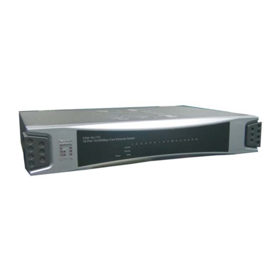
LED Indicators. Figure 2-1. The Front panel of the FSW-1641TX 16-port 10/100Base-TX Web Smart Switch Figure 2-2. The Front panel of the FSW-2441TX 24-port 10/100Base-TX Web Smart Switch LED Indicators The LED Indicators gives real-time information of systematic operation status. -
Page 8: Rear Panel
Status Description Green Power On Power Power is not connected Green In 100Mbps connection speed 100M In 10Mbps connection speed or no device connect Green The port is connecting with the device. LNK/ACT Blinks The port is receiving or transmitting data. No device attached. -
Page 9: Desktop Installation
Figure 2-2. The Rear Panel of FSW-1641TX Web Smart Switch Figure 2-2. The Rear Panel of FSW-2441TX Web Smart Switch Desktop Installation Set the Switch on a sufficiently large flat space with a power outlet nearby. The surface where you put your Switch should be clean, smooth, level and sturdy. - Page 10 Rack. The Switch can be placed in a wiring closet with other equipment. Perform the following steps to rack mount the switch: Position one bracket to align with the holes on one side of the switch and secure it with the smaller bracket screws. Then attach the remaining bracket to the other side of the Switch.
- Page 11 supply of the Switch works with voltage range of AC in the 100-240VAC, frequency 50~60Hz. Check the power indicator on the front panel to see if power is properly supplied.
-
Page 12: Network Application
3. Network Application This section provides you a few samples of network topology in witch the Switch is used. In general, FSW-1641TX/2441TX Web Smart Switch is designed as a segment switch. That is, with its address table (4k MAC address) and high performance, it is ideal for interconnecting networking segments. - Page 13 In the illustration below, two Ethernet switches with PCs, print server, and local server attached, are both connect to the Switch. All the devices in this network can communicate with each other through the Switch. Connecting servers to the Switch allow other users to access the data on server.
-
Page 14: Web Management
4. Web Management This section introduces the configuration and functions of the Web-Based management. About Web-based Management Inside the CPU board of the switch exists an embedded HTML web site residing in flash memory. It offers advanced management features and allow users to manage the switch from anywhere on the network through a standard browser such as Microsoft Internet Explorer. -
Page 15: System Login
System Login Install the switch on your network. Launch the Internet Explorer. Type http:// and the IP address of the switch. Press “Enter”. The login screen appears. Login Interface Key in the user name and password. The default user name “root” and password “... -
Page 16: Port Status
Port Status In Port status function, you can view all ports current status. Link Status: green means the port active. Gray means the port inactive. Speed: the port transmitting speed. Duplex: the port duplex mode. Flow Control: the port flow control status. - Page 17 Port Status interface Select the port and click Counters button, you can see the port counter information as the following figure shown. Click Refresh button to reset...
-
Page 18: Port Configuration
the counters. Click Cancel button will bring the screen back to previous page. Port Counter Information Interface Port Configuration You can configure speed, status, flow control, duplex mode, port base priority, port priority mapping and back pressure of each port. After configuration, click Apply button to apply the new configuration. -
Page 19: Vlan Setting
“Speed” and “Duplex” selection. Speed: set the port speed is 100M or 10M. Duplex: set the port duplex mode. Port Priority Mapping: set per port priority level. Back Pressure Support: enable or disable back pressure function. Port configuration interface VLAN Setting The system supports 16/24 VLAN groups. -
Page 20: Trunk Configuration
VLAN Setting Interface Trunk Configuration The system supports only one trunk group. The trunk group supports up to 4 port members. If the port members more than 4, it will cause the system abnormal. Mark the port number and click Apply button to apply the setting. -
Page 21: System Configuration
port 1, 2, 3, and 4. The trunk group members is port 1,2, 3 and 4 and port 1, 2, 3, and 4 are all in the VLAN group 1. System Configuration You can configure the IP, subnet mask, gateway, and firmware version that may vary with the factory firmware release period. - Page 22 firmware is. 5. Go to the Firmware Update interface and click Update button to star firmware loading. 6. After updated, please power off the switch and then power on the switch. Firmware Update Interface...
-
Page 23: Troubleshooting
5. Troubleshooting This section is intended to help you solve the most common problems on the FSW-1641TX/2441TX Web Smart Switch. Incorrect connections The switch port can auto detect straight or crossover cable when you link switch with other Ethernet device. For the RJ-45 connector should use correct UTP or STP cable, 10/100Mbps port use 2 pairs twisted cable and Gigabit 1000T port use 4 pairs twisted cable. -
Page 24: Diagnosing Led Indicators
between end nodes. In addition, you should make sure that your network topology contains no data path loops. Between any two ends nodes, there should be only one active cabling path at any time. Data path loops will cause broadcast storms that will severely impact your network performance. Diagnosing LED Indicators The Switch can be easily monitored through panel indicators to assist in identifying problems, which describes common problems you may encounter... -
Page 25: Technical Specification
6. Technical Specification This section provides the specifications of FSW-1641TX/2441TX Web Smart Switch. IEEE 802.3 10BASE-T Ethernet, Standard IEEE 802.3u 100BASE-TX Fast Ethernet IEEE802.3x Flow Control and Back-pressure Protocol CSMA/CD Technology Store and forward switching architecture Per port: Link/Activity, Full duplex/Collision, LED Indicators 100M Per unit: Power... - Page 26 MAC address 4K Mac with Auto Learning Memory 1.25Mbits Power Supply 100-240 VAC, 50~60Hz, 3.3V/4A Power 16 port: 14Watts(Maximum) Consumption 24 port: 18.5Watts(Maximum) Operation Temp. 0℃ to 45℃ (32℉ to 113℉) Operation Humidity 10% to 90% (Non-condensing) Storage Temp. -10℃ to 70℃ 266 mm (W) x 193 mm (D) x 44 mm (H);11 inch Dimensions size...
Need help?
Do you have a question about the FSW-2441TX and is the answer not in the manual?
Questions and answers