Panasonic DP-3030 Service Manual
Digital imaging systems
Hide thumbs
Also See for DP-3030:
- Specification sheet (4 pages) ,
- Specifications (2 pages) ,
- Service handbook (312 pages)
Table of Contents
Advertisement
Quick Links
Download this manual
See also:
Service Handbook
This service information is designed for experienced repair technicians only and is not intended for use by the general public.
It does not contain warnings or cautions to advise non-technical individuals of potential dangers in attempting to service a product.
Products powered by electricity should be serviced or repaired only by experienced professional technicians. Any attempt to service
or repair the product or products dealt within this service information by anyone else could result in serious injury or death.
Digital Imaging Systems
WARNING
© 2005 Panasonic Communications Co., Ltd.
All rights reserved. Unauthorized copying and distribution is
a violation of law.
Order Number: MGCS040801C0
DP-2310/3010
DP-2330/3030
[ Version 2.1 ]
H21
Advertisement
Table of Contents
Troubleshooting

Related Manuals for Panasonic DP-3030


Summary of Contents for Panasonic DP-3030
- Page 1 Order Number: MGCS040801C0 Digital Imaging Systems DP-2310/3010 DP-2330/3030 [ Version 2.1 ] WARNING This service information is designed for experienced repair technicians only and is not intended for use by the general public. It does not contain warnings or cautions to advise non-technical individuals of potential dangers in attempting to service a product. Products powered by electricity should be serviced or repaired only by experienced professional technicians. Any attempt to service or repair the product or products dealt within this service information by anyone else could result in serious injury or death. © 2005 Panasonic Communications Co., Ltd. All rights reserved. Unauthorized copying and distribution is a violation of law.
- Page 2 URL: http://www.senju-m.co.jp) is recommended when repairing PbF PCBs. The contents of this Service Manual and the Specifications are subject to change without notice. Panasonic Communications Co., Ltd. reserves the right to make improvements in the product design without reservation and without notice. Published in Japan.
-
Page 3: Important Notice
(similar to Windows OS when the power is abruptly interrupted), it is important to follow the step sequence below when turning OFF the Power Switches on the machine. 1. Turn the Power Switch on the Left Side of the machine to the OFF position first. 2. Wait approximately 10 seconds while the machine writes the closing status onto the Hard Disk Drive Unit. 3. Turn the Main Power Switch on the Back of the machine to the OFF position. (This interrupts all the power to the machine) 4. Unplug the AC Power Cord. * The specifications are subject to change without notice. Panasonic Communications Co., Ltd. reserves the right to make improvements in the product design without reservation and without notice. - Page 4 <Beispiel: DP-2330/3030> Hinweis:...
-
Page 5: For Your Safety
Precautions For Your Safety To prevent severe injury and loss of life, read this section carefully before servicing the Panasonic machine to ensure proper and safe operation of your machine. Please ensure that the machine is installed near a wall outlet and is easily accessible. -
Page 6: Operating Safeguards
Once a month, unplug the machine and check the power cord for the following. If you notice any unusual condition, contact the authorized Panasonic dealer The power cord is plugged firmly into the receptacle. The plug is not excessively heated, rusted, or bent. - Page 7 CAUTION Operating Safeguards Do not place a magnet near the safety switch of the machine. A magnet can activate the machine accidentally, resulting in injuries. Do not use a highly flammable spray or solvent near the machine. It can cause fire. When copying a thick document, do not use excessive force to press it against the scanning glass.
- Page 8 memo...
-
Page 9: Table Of Contents
Table of Contents Specifications Table ......11 System Description ......233 1.1. Copy Function.........11 6.1. Printing Process ........233 1.2. Fax, Printer and Internet Fax 6.2. Precaution with Consumables....234 Functions ..........20 6.3. New Image Stabilizing 1.3. System Combination.......29 Technology........... 236 1.4. -
Page 10: Table Of Contents
Table of Contents General Network Information ..... 391 8.15. Installing the Expansion F-ROM Board (DA-EM600) .......317 9.1. Network Protocol ........391 8.16. Installing the Sorting Image Memory 9.2. Layer Functions and Technology ..393 16 / 64 / 128 MB 9.3. -
Page 11: Specifications Table
DP-2310/3010 DP-2330/3030 1 Specifications Table 1.1. Copy Function Description Items Remarks DP-2310/2330 DP-3010/3030 Basic Specifications 1 Type Desktop 2 Platen Fixed 3 Original Position Platen Left / Rear ADF / i-ADF Left / Center 4 Recording Paper Path Center 5 Face Up / Face Down Face Down 6 Drum Organic Photo Conductor (OPC) - Page 12 DP-2310/3010 DP-2330/3030 Description Items Remarks DP-2310/2330 DP-3010/3030 17 Paper Feed Front Loading Universal Paper Tray Paper Tray Capacity 550 sheets x 2 Auto Size Setting USA and Canada Low Level Warning Empty Only LTR : 20 lb (75 g/m Bypass Capacity 50 sheets Other Destinations...
- Page 13 DP-2310/3010 DP-2330/3030 Description Items Remarks DP-2310/2330 DP-3010/3030 2 Cabinet Stand for Option Base Plate with Casters 4-Paper Tray Configuration Stand for Option Low Plain Stand 3-Paper Tray Configuration Stand for Option High Plain Stand 2-Paper Tray Configuration For EU and Other 3 Platen Cover Option Destinations...
- Page 14 DP-2310/3010 DP-2330/3030 Description Items Remarks DP-2310/2330 DP-3010/3030 Tray Position Outer Number of Bins Face Up / Face Down Face Down Bin Capacity 500 sheets LTR, LTR-R, A4, A4-R, B5 250 sheets LDR, LGL, A3, B4, FLS Max. 3 way using Optional Multi Tray Function Exit Tray (Inner) and Exit Tray (Outer) or Finisher.
- Page 15 DP-2310/3010 DP-2330/3030 Description Items Remarks DP-2310/2330 DP-3010/3030 Additional Optional Sorting Image Memory (Minimum 16 15 Hard Disk Drive Option MB) is required for the Hard Disk Drive to function. (For Tandem, Remote Copy, etc.) Features 1 Automatic Features Auto Magnification Selection Auto Paper Selection Auto Paper Tray Selection Reservation while Power On...
- Page 16 DP-2310/3010 DP-2330/3030 Description Items Remarks DP-2310/2330 DP-3010/3030 2-Sided Copy Inverse Mode (Negative / Positive) Centering Mode With Digital Sky Shot Mirror Mode Image Repeat Others (Inverting ADF & ADU) LDR → LTR x 2 2-Page Copy Mode (A3 → A4 x 2, B4 → B5 x 2) 2 in 1 4 in 1 6 in 1...
- Page 17 DP-2310/3010 DP-2330/3030 Description Items Remarks DP-2310/2330 DP-3010/3030 Job Complete Notice Trial Copy Mode Weekly Timer Function Mode Interrupt Electronic Counter Digital Sky Shot Mode Check / Slip Mode 3 Control Panel Display Wide Touch Panel LCD GREEN : Scanning / Status Lamp Printing : Alarm / Warning...
- Page 18 DP-2310/3010 DP-2330/3030 Description Items Remarks DP-2310/2330 DP-3010/3030 Number of Copies JOB Build and SADF / Multi Size Feed Mode Error Code Finishing Warning Indicators Add Toner Toner Waste Container Full Add Paper (No Paper) Add Paper (Under 50 sheets) Paper Jam Indication Paper Jam Location Service Alert Call User Error...
- Page 19 DP-2310/3010 DP-2330/3030 Description Items Remarks DP-2310/2330 DP-3010/3030 100% Inverting ADF 100% ADU Copy Productivity Throughput (LTR / A4) Transport Method Stack less When exiting to lower Inner 1→2 Tray from 1st Tray. 1 copy When LSU is ready. 5 copies 10 copies PM Cycle 1 PM Cycle...
-
Page 20: Fax, Printer And Internet Fax Functions
DP-2310/3010 DP-2330/3030 1.2. Fax, Printer and Internet Fax Functions 1.2.1. Fax Function Description Items Remarks DP-2310/2330 DP-3010/3030 Main Specifications 1 Compatibility ITU-T Std & Non-Std 2 PSTN Line Port 1-Line Only 3 Leased Line Port 4 V.24 Line Port 5 Modem Speed 33.6 - 2.4kbps T.30/V.34/V.17/V.29/V.27ter 6 Coding Scheme... - Page 21 DP-2310/3010 DP-2330/3030 Description Items Remarks DP-2310/2330 DP-3010/3030 5 Effective Scanning Width LDR (11.5 in) / A3 (292 mm) 6 A3 Size TX/RX Conforms to ITU-T A3 7 Reduction XMT A3 to B4 / A3 to A4 / B4 to A4 8 ADF Capacity 50 sheets Face-Up, feed from top page...
- Page 22 DP-2310/3010 DP-2330/3030 Description Items Remarks DP-2310/2330 DP-3010/3030 Full Number Dialing Max. 70 stations (Buffered Dialing) Direct Dialing Voice mode (Monitor Dialing) 9 Automatic Redialing Up to 15 times at 0 to 15 min. intervals 10 Manual Redialing Pressing the REDIAL/PAUSE button 11 Line Monitor Speaker 12 Chain Dialing (Hybrid Dial) In Monitor Dialing mode only...
- Page 23 DP-2310/3010 DP-2330/3030 Description Items Remarks DP-2310/2330 DP-3010/3030 Distinctive Ring Detector (DRD) 90 Degree Rotation Reception 8 Duplex Printing Polling 1 Polling 2 Turnaround Polling 3 Multi-Station Polling Max. 270 stations 4 Deferred Polling Max. 50 timers Deferred Multi-Station Max. 50 timers / 270 stations Polling 6 Direct Polling Tx 7 Memory Polling Tx...
- Page 24 DP-2310/3010 DP-2330/3030 Description Items Remarks DP-2310/2330 DP-3010/3030 Special Communications 1 Password XMT / RCV 2 Selective Reception TSI Check 3 Relay XMT Request 4 Relay XMT Center 5 Confidential XMT / Polling 6 Confidential Center 7 Mailbox XMT / Polling 8 Mailbox Center 9 File XMT Received File Transfer...
-
Page 25: Printer Function
DP-2310/3010 DP-2330/3030 1.2.2. Printer Function Description Items Remarks DP-2310/2330 DP-3010/3030 Interface 1 Centronics Parallel I/F Ethernet 10Base-T/ 2 LAN (Network) 100Base-TX 3 USB Port 4 IEEE-1394 Printer Function LDR, LGL, LTR, LTR-R, INV-R For USA and Canada 1 Printing Size A3, A4, A4-R, A5, A5-R, B4, FLS For EU A3, B4, A4, A4-R, B5, B5-R For Other Destinations... - Page 26 DP-2310/3010 DP-2330/3030 1.2.3. Network Scanner Function Description Items Remarks DP-2310/2330 DP-3010/3030 Interface 1 Centronics Parallel I/F Ethernet 10Base-T/ 2 LAN (Network) 100Base-TX 3 USB Port 4 IEEE-1394 Firewire Network Scanning Function 1 Scanning Device CCD (i-ADF / Platen) ITU-T Image No. 1 (A4, Std 2 Scanning Speed (ADF) 30 opm Resolution), JBIG, 600 dpi...
- Page 27 DP-2310/3010 DP-2330/3030 1.2.4. Internet Fax Function Description Items Remarks DP-2310/2330 DP-3010/3030 Main Specifications 1 Communication Protocols SMTP / POP3 / MIME 2 Max. Modem Speed 3 Coding Scheme JBIG/MMR/MR/MH Selectable (PDF format can be used for Scan- to-Email when sending to a PC. 4 File Format TIFF / PDF However, since current Internet Fax...
- Page 28 Emulation Kit 8 DHCP Client 9 LDAP Lightweight Directory Access Protocol 10 TIFF Viewer Selectable, PDMS / TIFF Viewer Certainty Email from RCV side to Panasonic 1 Comm. Journal (w / Image) Internet FAX's only 1 Email Address Ver.2.1 MAR 2005...
-
Page 29: System Combination
DP-2310/3010 DP-2330/3030 1.3. System Combination Inverting ADF (i-ADF) ADF PC Board Scanner Unit Document Sensor (SDR PC Board) Motor Panel Main PC Board PCL6 Fax Communication (PNL PC Board) (SC PC Board) Emulation Option Option (FXB) PS/PCL6 Printer Emulation Option Network Scanner Option Interface... -
Page 30: Options List
DP-2310/3010 DP-2330/3030 1.4. Options List Options Option Name Option Number Remarks Printer Controller Module for PCL6 DA-PC300 For DP-2310 / 3010 Multi Page Description Language DA-MC300 Controller Module for PS/PCL6 Printer Controller Module for PCL6-IPX/ DA-PC301 For DP-2330 / 3030 (For USA and Canada, can also be used Multi Page Description Language for DP-2310 / 3010 without IPX/SPX) - Page 31 DP-2310/3010 DP-2330/3030 Supplies Part Name Part Number Remarks Toner DQ-TU15E 15 k Staple Cartridge FQ-SS32 OPC Drum DQ-H60E Developer DQ-Z120E Note: PCL6 is a Page Description Language of the Hewlett-Packard Company. PS3 is a Page Description Language of the Adobe Systems Company. Available in Specified Destinations Ver.
-
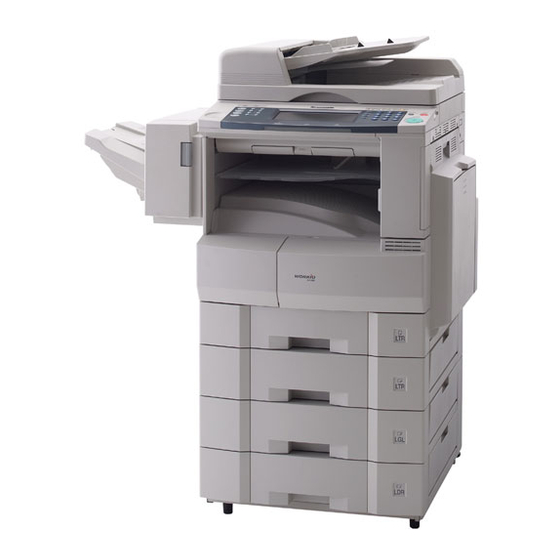
Page 32: External View
DP-2310/3010 DP-2330/3030 1.5. External View 1. Standard Configuration (For USA Only) Product complies with DHHS Rules 21 CFR Subchapter J in effect at date of manufacture. Top View Manufacturer's Name and Address Factory ID 27.83 in (707 mm) 23.58 in (599 mm) Left View Front View Right View... - Page 33 DP-2310/3010 DP-2330/3030 3. Space Requirements With Options Copier 3.94 in (100 mm) 14.2 in (379 mm) 23.58 in (599 mm) 3.94 in (100 mm) 51.65 in (1312 mm) 15.94 in (405 mm) 3.94 in (100 mm) 46.38 in (1178 mm) Copier + Outer Exit Tray 3.94 in (100 mm) 3.46 in (88 mm)
- Page 34 For Example: = DP-2310-PU = DP-2310-PB = DP-3010-PU DP-3010-PB = DP-2330-PU = DP-2330-PB = DP-3030-PU DP-3030-PB Production Facility Production Year Starting with Year 2001, the last 2-digits of the year is represented as: A ~ T A : 01 (2001)
-
Page 35: Control Panel
DP-2310/3010 DP-2330/3030 1.6. Control Panel DP-2310/3010 DP-2330/3030 Ver. 2.1 MAR 2005... -
Page 36: Fans And Motors
DP-2310/3010 DP-2330/3030 1.7. Fans and Motors Transport Motor (1320) ADF Motor (1801) Scanning Motor (201) Main Motor (907) Fan (459) LVPS Fan (322) Toner Motor (958) LSU Fan (315) Lift DC Motor (1152) 1.8. Clutches and Switches ADF Roller Clutch (1788) Intermediate Clutch (969) Feed 2 Roller... -
Page 37: Pc Boards
DP-2310/3010 DP-2330/3030 1.9. PC Boards SDR PCB (1903) SNS PCB (1981) LFB PCB (1969) ADF PCB (1907) PNL4 PCB (114) PNL3 PCB (113) CCD (207) EXFD PCB (1978) PNL1 PCB (1908) MJR PCB (1915) PNL2 PCB (123) FXB PCB (1916) CDS PCB (1986) DC PCB (1905) ACD PCB (1904) -
Page 38: Disassembly Instructions
DP-2310/3010 DP-2330/3030 2 Disassembly Instructions 2.1. General Disassembly Pertinent Disassembly Instruction sections are shown below. Ver.2.1 MAR 2005... - Page 39 DP-2310/3010 DP-2330/3030 2.2. Disassembly Instructions 2.2.1. Inverting-Automatic Document Feeder (i-ADF) Unit (1) Open the ADF Cover (1831). (2) Remove 4 Silver Screws (B1). (3) Lift the ADF Input Tray (1604). (4) Slightly pull the right edge of the ADF Rear Cover upward.
- Page 40 DP-2310/3010 DP-2330/3030 (15) Remove the Snap Ring (S9). (16) Remove the Pin (744). (17) Remove the ADF Shaft (1724). (18) Remove the ADF Roller (1728). (19) Remove the Snap Ring (S9). (20) Remove the Pre-Feed Roller Shaft (1730). (21) Remove the Pre-Feed Roller (1731). (22) Remove 1 Silver Screw (B1).
- Page 41 DP-2310/3010 DP-2330/3030 (30) Disconnect all Connectors on the ADF PC Board. (31) Remove 2 Screws (19). (32) Remove the ADF PC Board (1907). (33) Remove 2 Screws (24). (34) Remove the ADF Motor (1801). (35) Remove 6 Screws (19). (36) Remove the Sensor Bracket (1663). (37) Remove 4 Screws (19).
- Page 42 DP-2310/3010 DP-2330/3030 < Cleaning ADF Roller, Pre-Feed Roller, Drive Roller and Feed 2 Roller> (1) Open the ADF Cover (1831). (2) Clean the ADF Roller (1728), Pre-Feed Roller (1731), Drive Roller (1872) and the Feed 2 Roller (1753) with a soft cloth, saturated with isopropyl alcohol.
- Page 43 DP-2310/3010 DP-2330/3030 2.2.2. Control Panel Unit (1) Pull the Battery Holder (104) part of the way out. (2) Release the Latch and remove the Battery Holder (104) out. (3) Remove 6 Silver Screws (B1). (4) Remove the Left Platen Cover (514) and the Right Platen Cover (516).
- Page 44 DP-2310/3010 DP-2330/3030 (11) Remove 4 Screws (F10). (12) Remove the PNL1 PC Board (1908). (13) Remove 7 Screws (F10). (14) Disconnect the Harness on the PNL2 PC Board (CN251). (15) Remove the PNL2 PC Board (123). Note: After reassembling the Control PNL2 PC Board, make sure that the Battery Holder is reinstalled.
- Page 45 DP-2310/3010 DP-2330/3030 (21) Remove 1 Screw (P5). (22) Remove the PNL4 PC Board (114). (23) Remove 4 Screws (P5). (24) Remove the PNL3 PC Board (113). (25) Remove 2 Screws (H4). (26) Remove 2 Screws (H4). (27) Remove the LCD Module (128). (28) Remove the Touch Panel (127).
-
Page 46: Scanner Unit
DP-2310/3010 DP-2330/3030 2.2.3. Scanner Unit (1) Remove the Left and Right Platen Covers (514, 516) and the Control Panel Assembly. (Refer to 2.2.2.) (2) Remove 2 Screws (19). (3) Remove the Glass Assembly (557). (4) Remove the Glass S (559). (5) Holding by the center, slowly move the Lamp Base Assembly to the center of the Scanner Base Frame in the direction shown by the arrow. - Page 47 DP-2310/3010 DP-2330/3030 (8) Remove 2 Screws (19). (9) Remove the 2 Lamp Plate Springs (232). (10) Disconnect the Harness on the LFB PC Board (CN181). (11) Remove the Scanning Lamp (204). (12) Remove 2 Mirror Plate Springs (230). (13) Remove Mirror 1 (264). Note: Observe the position of the Mirror 1 before removing it.
- Page 48 DP-2310/3010 DP-2330/3030 (19) Remove 2 Red Screws (D24). (20) Remove the FPC Cable Holder A (215) Assembly. (21) Holding by the center, slowly move the Lamp Base Assembly towards the left of the Scanner Base Frame. (22) Disconnect the Harness on the LFB PC Board (CN181).
- Page 49 DP-2310/3010 DP-2330/3030 (31) Remove the E-Ring (5Y). (32) Remove the Synchro Belt (208). (33) Remove the MXL34 Pulley (217). (34) Remove 1 Screw (6P). (35) Remove the Fan (459). (36) Disconnect the Harness on the Scanning Motor. (37) Remove 3 Screws (19). (38) Remove the Motor Bracket (249) Assembly.
- Page 50 DP-2310/3010 DP-2330/3030 (41) Disconnect the Harness on the SC PC Board (CN106). (42) Release 2 Latch Clips and remove the Ferrite Core. (43) Remove 3 Red Screws (D24). (44) Remove the CCD Assembly (207). Note: When reinstalling the CCD Assembly, align the hole with the Red Mark on the CCD Assembly with the hole on the Scanner Base Frame as illustrated and secure it with 3 Red Screws.
- Page 51 DP-2310/3010 DP-2330/3030 (47) Remove 2 Screws (19). (48) Remove the SDR PC Board (1903). (49) Remove 6 Screws (19). (50) Remove the F/R Scanner Frame (240). (51) Remove 2 Red Screws (D24). (52) Remove the Rear Lamp Belt Lock (228). (53) Remove the Front Lamp Belt Lock (227).
- Page 52 DP-2310/3010 DP-2330/3030 (56) Remove 2 Screws (18). (57) Remove the Rear Mirror Belt Lock (238). (58) Remove the Front Mirror Belt Lock (236). (59) Remove the Mirror 2 Bracket (233) Assembly. (60) Remove the 4 Mirror 2 Plate Springs (206). (61) Remove the two Mirror 2 (265).
- Page 53 DP-2310/3010 DP-2330/3030 (3) Install the Mirror 2 Bracket (233) Assembly. (4) Reinstall the 2 Inner Timing Belts (202). Note: The Bracket must be adjusted by moving it towards the center until it stops against the notches in the frame. (5) While holding each side of the Bracket against the notch, secure the Rear Mirror Belt Lock (238) and the Front Mirror Belt Lock (236) with 2 Screws (18).
- Page 54 DP-2310/3010 DP-2330/3030 (8) Clean the Mirror 1 (264) and both the Mirror 2 (265) with a soft cloth, saturated with isopropyl alcohol. Ver.2.1 MAR 2005...
-
Page 55: Process Unit
DP-2310/3010 DP-2330/3030 2.2.4. Process Unit (1) Open the Right Cover (1201). (2) Remove 1 Screw (6P). (3) Remove the Harness Cover (1525). (4) Unlock the Angled Rear Arm (1218) and the Front Arm (1217). (5) Open the Right Cover and hook the Angled Rear Arm into the lower Hook Hole. - Page 56 DP-2310/3010 DP-2330/3030 (11) Disconnect the Harness. (12) Loosen the Process Unit Screw (743). (13) Slide the Process Unit out. Caution: To prevent damage to the Process Unit, ensure the Right Cover is still open before pulling the Process Unit out. Caution: Exercise caution not to scratch the surface of the OPC Drum (Green), and not to touch it with bare...
- Page 57 DP-2310/3010 DP-2330/3030 (19) Remove the Harness from clamp, disconnect the Connector. (20) Remove 2 Screws (51) and 1 Snap Ring (G6). (21) Remove the Hopper Unit. Note: When reinstalling the Hopper Unit, insert the hooks into the recessed holes on the Developer Unit as illustrated.
- Page 58 DP-2310/3010 DP-2330/3030 (26) Shake the Developer Bottle thoroughly (approx. 30 seconds). (27) Pour the appropriate developer evenly into the developer unit. Make sure to empty the bottle. (28) Close the Developer Cover. Note: When reinstalling the Developer Cover, ensure that 2 Magnet Roller Sheets are outside as illustrated.
- Page 59 DP-2310/3010 DP-2330/3030 (33) Remove the Cleaning Roller (706). (34) Remove 2 Bias Charge Roller Holder (728) Assemblies. Note: When reinstalling the Bias Charge Roller Holder Assembly on the rear side, install the Bias Charge Roller Holder (728) first and then the Bias Charge Roller Bushing (726) with the Bushing Coil Spring (727) as illustrated.
-
Page 60: Fuser Unit
DP-2310/3010 DP-2330/3030 2.2.5. Fuser Unit CAUTION: To prevent from getting burned, do not install, remove, clean or make adjustments when the Fuser Unit is hot. (1) Open the Right Cover (1201). (2) Remove 1 Screw (6P). (3) Remove the Harness Cover (1525). (4) Unlock the Angled Rear Arm (1218) and the Front Arm (1217). - Page 61 DP-2310/3010 DP-2330/3030 (10) Disconnect 2 Harnesses. (11) Remove 4 Screws (4N). (12) Remove the Fuser Unit. (13) Remove 4 Screws (6P). (14) Remove the Dual-Path Exit Guide. (15) Clean the Feed Roller (1510) with a soft cloth, saturated with isopropyl alcohol. (16) Clean the Feed Roller (1510) with a soft cloth, saturated with isopropyl alcohol.
- Page 62 DP-2310/3010 DP-2330/3030 (17) Remove 3 Screws (4N). (18) Remove the Lower Fuser Cover (1003). <Removing the Web Cleaning Roller> (19) Remove 2 Screws (21). (20) Disconnect the Harness. (21) Remove the Cleaning Web Roller Unit. (22) Remove 1 Screw (21). (23) Remove the Rear Web Bracket (1071).
- Page 63 DP-2310/3010 DP-2330/3030 (31) Remove 3 Screws (23). (32) Remove 2 Screws (19). (33) Remove the Harness Guide (1004). (34) Remove 1 Screw (21). (35) Remove the Rear Lamp Holder (1021). (36) Remove 2 Screws (16). (37) Remove 1 Screw (21). (38) Remove the Front Lamp Holder (1018).
- Page 64 DP-2310/3010 DP-2330/3030 (39) Remove 2 Fuser Lamps (1043 and 1044). Note: Make sure to check the wattage of each Fuser Lamp when replacing. <Fuser Lamps Handling Precautions> Note: 1. When reinstalling, route the Harnesses along the hooks as illustrated. 2. Be sure to install the longer Harness to the Gear side and the shorter Harness to the other side.
- Page 65 DP-2310/3010 DP-2330/3030 (42) Remove the Fuser Roller (1026) Assembly. (43) Remove the 2 C-Rings (1078). (44) Remove the E40 Heat Roller Gear (1014). (45) Remove the Plate Spacer (1023). (46) Remove the 2 Insulation Bushings (1006). (47) Remove the 2 Bearings (1046). Note: 1.
- Page 66 DP-2310/3010 DP-2330/3030 (51) Remove the Exit Roller (1028). (52) Remove the Turn Guide (1007). (53) Remove 1 Screw (19). (54) Remove the Upper Guide (1001). (55) Remove 5 Upper Fingers (1067). (56) Remove the Pressure Roller (1027). Ver.2.1 MAR 2005...
- Page 67 DP-2310/3010 DP-2330/3030 (57) Remove 2 Bearings (1039). Note: 1. When reinstalling, make sure to install with Bearing's Retainer Ring facing towards the Roller. 2. Do not scratch the surface of the Pressure Roller when removing or reinstalling it. <Cleaning Pressure Roller> Clean the surface of the Pressure Roller with a soft cloth, saturated with isopropyl alcohol.
-
Page 68: Drive Unit
DP-2310/3010 DP-2330/3030 2.2.6. Drive Unit (1) Remove 4 Silver Screws (S6). (2) Open the Rear Cover (302). (3) Remove 4 Silver Screws (S6). (4) Remove the Rear Right Cover (507) and the Right Rear Cover (518). (5) Remove 2 Silver Screws (B1). (6) Remove the Lower Rear Cover (506). - Page 69 DP-2310/3010 DP-2330/3030 (12) Disconnect the MT Harness (1926) on the Main Motor (CN1 and CN2). (13) Remove 5 Screws (4N). (14) Remove the Main Motor (907). (15) Disconnect the Connector on each of the 3 Clutches. (16) Remove 3 Snap Rings (S9). (17) Remove 3 Clutches (969, 1105 x 2).
- Page 70 DP-2310/3010 DP-2330/3030 (23) Remove 3 Screws (19). (24) Remove the Motor Bracket (908). Ver.2.1 MAR 2005...
-
Page 71: Right Cover
DP-2310/3010 DP-2330/3030 2.2.7. Right Cover (1) Open the Right Cover (1201). (2) Remove 1 Screw (6P). (3) Remove the Harness Cover (1525). (4) Unlock the Angled Rear Arm (1218) and the Front Arm (1217). (5) Hook the Angled Rear Arm (1218) into the lower hook hole. - Page 72 DP-2310/3010 DP-2330/3030 (11) Remove 1 Screw (19). (12) Remove the Registration Pinch Roller (1222). <Cleaning Registration Pinch Roller> Clean the surface of the Registration Pinch Roller with a soft cloth, saturated with isopropyl alcohol. (13) Remove the Roller Cleaner (1229). Note: When installing the Roller Cleaner, make sure that turn a felt of black side upwards as illustrated.
- Page 73 DP-2310/3010 DP-2330/3030 (16) Remove the BTR Gear (1234). (17) Remove the Bias Transfer Roller (1221). <Cleaning Bias Transfer Roller> Clean the surface of the Bias Transfer Roller only with a soft dry cloth. Ver. 2.1 MAR 2005...
-
Page 74: Sheet Bypass
DP-2310/3010 DP-2330/3030 2.2.8. Sheet Bypass (1) Remove 1 Screw (19). (2) Remove 1 Screw (1Y). (3) Remove the Snap Ring (S9). (4) Remove the P6L5 Conductive Bushing (972). (5) Remove the Dual-Path Guide (1203). (6) Remove 1 Screw (19). (7) Remove the Feed Roller (1244). <Cleaning Feed Roller>... - Page 75 DP-2310/3010 DP-2330/3030 (10) Remove 1 Screw (X6). (11) Remove the Reverse Roller Guide (1294). (12) Remove the Reverse Roller (1291) Assembly. (13) Remove the Bushing (1286). (14) Remove the Washer (1288). (15) Remove the E-Ring (J7). (16) Remove the Reverse Roller (1291). <Cleaning Reverse Roller>...
- Page 76 DP-2310/3010 DP-2330/3030 2.2.9. Paper Feed Module (1) Remove the Process Unit. (Refer to 2.2.4.) (2) Remove the Clutch (1105). (Refer to 2.2.6.) (3) Remove the Snap Ring (S9). (4) Remove the Registration Roller (1121). <Cleaning Registration Roller> Clean the surface of the Registration Roller with a soft cloth, saturated with isopropyl alcohol.
- Page 77 DP-2310/3010 DP-2330/3030 (11) Remove the Reverse Clutch (1132) and Spring D (1178). (12) Remove the C25 Gear Roller (1145). <Cleaning C25 Gear Roller> Clean the surface of the C25 Gear Roller with a soft cloth, saturated with isopropyl alcohol. (13) Slide the 2nd Paper Tray out. (14) Open the Jam Access Cover (2307).
-
Page 78: Lsu Unit
DP-2310/3010 DP-2330/3030 2.2.10. LSU Unit (1) Remove the Process Unit. (Refer to 2.2.4.) (2) Slide the 1st Paper Tray out. (3) Remove 1 Screw (19) and 2 Screws (6P). (4) Remove the Front Left Cover (534). (5) Remove the Blind Cover (530). (6) Remove 2 Screws (S6). -
Page 79: Paper Transport Unit
DP-2310/3010 DP-2330/3030 2.2.11. Paper Transport Unit <Cleaning the Pinch Roller> (1) Remove the Inner Tray (1522). (2) Push open the Paper Transport Jam Cover (1302). (3) Clean 6 Pinch Rollers (1518) with a soft cloth, saturated with isopropyl alcohol. Ver. 2.1 MAR 2005... - Page 80 DP-2310/3010 DP-2330/3030 2.2.12. PC Board (1) Remove 7 Screws (6P). (2) Disconnect all the Harnesses on the SC PC Board. (3) Remove the SC PC Board (1901). (4) Remove 3 Screws (6P). (5) Disconnect all the Harnesses on the SPC PC Board.
- Page 81 DP-2310/3010 DP-2330/3030 (10) Remove 6 Screws (6P). (11) Disconnect all the Harnesses on the ACD PC Board. (12) Remove the ACD PC Board (1904). (13) Remove 2 Screws (6P). (14) Disconnect all the Harnesses on the DC PC Board. (15) Remove the DC PC Board (1905). (16) Remove 9 Screws (6P).
-
Page 82: Screw Identification Template
DP-2310/3010 DP-2330/3030 2.3. Screw Identification Template * For DP-2330/3030 Ref. No. Part No. Figure Remark Screw XYN3+J8FJ Screw * XYN3+J8 Screw XYN3+J6FJ Screw * XYN3+J6 XTB3+8JFJ Screw Screw * XTB3+8J XTB3+8FFJ Screw Screw * XTB3+8F XTB3+6FFJ Screw Screw * XTB3+6F Screw XYN3+F8FJ Screw *... - Page 83 DP-2310/3010 DP-2330/3030 Figure Ref. No. Part No. Remark Screw XSN3+W8FJ Screw (For DP-2310/3010 only) XSN3+W8FC XYN3+F4FJ Screw Screw (For DP-2310/3010 only) XYN3+F4 E-Ring XUC4FJ E-Ring (For DP-2310/3010 only) XUC4 E-Ring XUC6FJ E-Ring (For DP-2310/3010 only) XUC6 Screw XTW3+6LFJ Screw (For DP-2310/3010 only) XTW3+6LFC Screw XTB26+6JFJ...
- Page 84 DP-2310/3010 DP-2330/3030 Ref. No. Part No. Figure Remark DZPA000063 Screw DZPK000021 Washer XSN4+W10FN Silver Screw XTN3+10G Screw Screw XTB3+8GFJ XTB3+8G Screw (For DP-2310/3010 only) FFPFJ0039B Snap Ring Screw XTB26+8JFJ Screw (For DP-2310/3010 only) XTB26+8J FFPFJ0033B Snap Ring FFPFJ0041B Snap Ring XUC3VM E-Ring XUC4VM...
- Page 85 DP-2310/3010 DP-2330/3030 Ref. No. Part No. Figure Remark DZPA000064 Tumb Screw Screw XTB4+10FFJ Screw (For DP-2310/3010 only) XTB4+10F Screw XTB3+6FFJ-RP Screw (For DP-2310/3010 only) B3x6TTS-RP XTB3+12JFJ Screw Screw (For DP-2310/3010 only) XTB3+12J XTN3+8G Screw FFPFA0152 Screw DZPA000086 Screw XTB3+12FFJ Screw XTB3+12F Screw (For DP-2310/3010 only) DZJM000171...
-
Page 86: Check Points
DP-2310/3010 DP-2330/3030 3 Maintenance, Adjustments and Check Points 3.1. Preventive Maintenance Preventive maintenance is performed at specific intervals and consists of machine cleaning and parts replacement. It is essential to perform these service activities properly and at the specified intervals for customer satisfaction. - Page 87 DP-2310/3010 DP-2330/3030 Laser Handling Precautions The optical laser system employed by this photocopier is completely sealed by a protective housing and an external cover. Therefore, the laser beam will not stray or leak during photocopying operation. However, when servicing the photocopier, take the following precautions: 1.
-
Page 88: Required Tools
DP-2310/3010 DP-2330/3030 3.2. Required Tools Tools Tools Soft Cloth Pliers Isopropyl Alcohol Cotton Swab Phillips Screwdriver (#2) Brush KS-660 - Conductive Grease Stubby Phillips Screwdriver (#2) (Available from Shin-Etsu Silicones of America, Inc. URL: http://www.shinetsusilicones.com) Molykote EM-50L Grease Slotted Screwdriver (3/32 in) (Available from Dow Corning, URL: http://www.dowcorning.com) Tweezer... -
Page 89: Preventive Maintenance Points
DP-2310/3010 DP-2330/3030 3.3. Preventive Maintenance Points DETAIL B DETAIL A 12 14 15 12 14 15 Ver. 2.1 MAR 2005... - Page 90 DP-2310/3010 DP-2330/3030 26 27 28 DETAIL A 30 31 DETAIL B Ver.2.1 MAR 2005...
-
Page 91: Preventive Maintenance Check List
DP-2310/3010 DP-2330/3030 3.4. Preventive Maintenance Check List Cleaning Replacement/Adjustment Ref. Ref. Mechanical Parts Cycle Cycle Counter Method Procedure (Sheet) (Sheet) i-ADF/ADF Unit 1 ADF Roller 1728 Alcohol 120K Refer to F7-02-03 2.2.1. 2 Pre Feed Roller 1731 Alcohol 120K 3 Separation Roller 1740 Alcohol 120K... - Page 92 To verify the counter information, print the Total Counter List using the Service Mode: F7 - Electronic Counter - 00 (List Print). 3. Cleaning, Replacement and Adjustment Cycle (Sheet) are based on using Panasonic's recommended standard paper and supplies. These cycles may vary with the kind of paper used and/or ambient conditions.
-
Page 93: Resetting The P/M Preventive Maintenance) Counter
DP-2310/3010 DP-2330/3030 3.5. Resetting the P/M (Preventive Maintenance) Counter When the machine reaches the preset P/M Cycle, it will show "Call for P/M" or "Replace The Toner Waste Container" on the LCD Display. The PM Counter can be reset by following the procedures below. 3.5.1. -
Page 94: Lubrication Point List
DP-2310/3010 DP-2330/3030 3.6. Lubrication Point List This information is used for routine Preventive Maintenance (PM) calls to ensure the highest degree of reliability. Inspect the following areas and lubricate as required. The inspection interval is usually 120K copies or more, however the interval may be reduced due to environmental conditions. Ref. - Page 95 DP-2310/3010 DP-2330/3030 Ref. Mechanical Parts Grease Lubrication Point Idle Roller Plate 1509 EM-50L Spring Idle Roller 1511 Roller Shaft 1313 EM-50L Pinch Roller 1518 Paper Transportation Drive Roller 1314 EM-50L P6L8 Bushing 1322 Roller Shaft 1313 EM-50L Pinch Roller 1518 Ver.
- Page 96 DP-2310/3010 DP-2330/3030 Ref. Mechanical Parts Grease Lubrication Point Automatic Duplex Unit Bias Transfer Roller 1221 EM-50L (BTR) KS-660 Registration Pinch 1222 Roller Front Bushing 1231 Rear Bushing 1233 Roller Shaft 1313 EM-50L Pinch Roller 1518 Drive Roller 1409 EM-50L P6L5 Bushing 1150 Pinch Spring 1411...
-
Page 97: Updating The Firmware
Tool (FUP) using Ethernet LAN Port and a Crossover Cable. The Network FUP Tool version must be 3.XX or higher, and it can be found on the Panasonic Document Management System CD-ROM included with the main unit or on the CD-ROM included with the PCL or PS/PCL options. - Page 98 DP-2310/3010 DP-2330/3030 (2) For PCL Option The PCL Control Program (2) must be written into the 4 MB onboard, which is assigned as ROM Code (B). The PCL Control Program (3) and PCL Font data (4) are written into the 8 MB in the SLOT 1.
- Page 99 LAN. 1) Install the Network Firmware Update Tool to your PC The option CD-ROM or the Panasonic Document Management System CD-ROM includes the Network Firmware Update Tool and the Main Unit Firmware Code are located in the Option CD-ROM only.
- Page 100 If the device is not connected to the LAN, upgrade the firmware code using the USB Port. 1) Install the Local Firmware Update Tool to your PC The option CD-ROM or the Panasonic Document Management System CD-ROM includes the Local Firmware Update Tool and the Main Unit Firmware Code are located in the Option CD-ROM only.
- Page 101 4) Upgrading the Main Unit's Firmware Code Start the Local Firmware Update Tool and select the following Firmware Code Parent File Folder in the C:\Panasonic\Panasonic-FUP\Data folder, and select the Firmware Code Type then follow the display instructions to upgrade the Main Unit's Firmware Codes.
- Page 102 A. Utilizing the Firmware Update Kit 1) Install the Local Firmware Update Tool to your PC The option CD-ROM or the Panasonic Document Management System CD-ROM includes the Local Firmware Update Tool and the Main Unit Firmware Code are located in the Option CD-ROM only.
- Page 103 DP-2310/3010 DP-2330/3030 OFF position. (See 3.7.7.) 2. Insert the Flash Memory Card (4 MB or 8 MB) into the machine. 3. Turn the Main Power Switch on the back and the Power Switch on the left side of the machine to the ON position.
- Page 104 DP-2310/3010 DP-2330/3030 3.7.7. Notice after installing the HDD option After the Hard Disc Drive Unit is installed, to prevent a Disc Scan Function from being performed (similar to Windows OS when the power is abruptly interrupted), it is important to follow the step sequence below when turing OFF the Power Switches on the machine.
-
Page 105: Firmware Version
DP-2310/3010 DP-2330/3030 3.7.9. Firmware Version DP-2310/3010 DP-SFDL2 A A Vxxxxx (AU) Destination Code (Fax) AU : USA/Canada AB : UK Destination Code (Copier) PU : USA/Canada PB : UK Division Soft (When it is divided into (a) and (b)) Firmware Version (V1xxxx) Language Code A : A-English, C-French &... - Page 106 DP-2310/3010 DP-2330/3030 SFDL2 SPC A A Vxxxxx Firmware Version (V1xxxx) AA: Fixed Model Number DP-2330/3030 SFD L25R A A Vxxxxx (AU) Destination Code (Fax) AU : USA/Canada AB : UK Destination Code (Copier) PU : USA/Canada PB : UK Division Soft (When it is divided into (a) and (b)) Firmware Version (V1xxxx) Language Code...
- Page 107 DP-2310/3010 DP-2330/3030 L25R PNL A A Vxxxxx (AU) Destination Code (Fax) AU : USA/Canada AB : UK Destination Code (Copier) PU : USA/Canada PB : UK Division Soft (When it is devided into (a) and (b)) Firmware Version (V1xxxx) Language Code A : A-English, C-French &...
-
Page 108: Adjusting The Printer Registration Lsu Image Side To Side
DP-2310/3010 DP-2330/3030 3.8. Adjusting the Printer Registration, LSU Image Side to Side When installing the Paper Tray option, the following LSU Image Side to Side adjustment must be performed. The Printer registration is adjusted at the factory. If copy image is abnormal, specially in the Rotation Copy mode, adjust it by the following procedure. 3.8.1. - Page 109 DP-2310/3010 DP-2330/3030 5. Perform the Service Mode F6-16 (ADU Side Adjust), to adjust the gap to be 5 mm. 6. If the gap is less than 5 mm, input a (+) value. If more than 5 mm, input a (-) value. 7.
-
Page 110: Calibrating The Lcd
DP-2310/3010 DP-2330/3030 standby. Note: This is the size adjustment and do not worry about the positioning. 3.8.7. ADF Original Read Edge & ADF Main Scan Adjustments 1. Place the Original Document on the ADF. 2. Insert Ledger or A3 size paper into the 1st tray and change the tray setting to the appropriate paper size. -
Page 111: Troubleshooting
DP-2310/3010 DP-2330/3030 4 Troubleshooting 4.1. Initial Troubleshooting Flowchart START Plug the Power Cord in and turn the Power Switches ON. Does the unit power up normally? Does the LCD display the function correctly? Troubleshoot Improper LCD Display Troubleshoot any 3-digit CODE displayed Does the unit produce normal copies? -
Page 112: Improper Lcd Display
DP-2310/3010 DP-2330/3030 4.2. Improper LCD Display START Check connectors: CN52 (SC PCB) and CN220 (PNL1 PCB). Does the display appear normal? Is LED/LCD displayed? Does CN52, pin 3 on the SC PCB measure +5 VDC? Replace the LCD Replace the Replace the SC PCB. -
Page 113: Printed Copy Quality Problems
DP-2310/3010 DP-2330/3030 4.3. Printed Copy Quality Problems 4.3.1. Black Copy START Is the Test Pattern printout in Copier F1 Mode or Fax Service Mode 3 normal? Check the Scanner mechanism. Is the OPC Drum/Developer Unit operational? Replace the OPC Drum/Developer Unit. Is the PS normal? 1. - Page 114 DP-2310/3010 DP-2330/3030 4.3.2. Blank Copy START Is the Test Pattern printout in Copier F1 Mode or Fax Service Mode 3 normal? Check the Scanner mechanism. Is the OPC Drum/Developer Unit operational? Replace the OPC Drum/Developer Unit. Are there any foreign particles or stains in the Charge Unit? 1.
-
Page 115: Vertical White Lines
DP-2310/3010 DP-2330/3030 4.3.3. Vertical White Lines START Is the Test Pattern printout in Copier F1 Mode normal? Check the Scanner mechanism. Is the recording paper damp? Replace the recording paper. Is the Drum/Developer Unit operational? Replace the Drum/Developer Unit. Are there any foreign particles or stains blocking the Laser Beam path? 1. -
Page 116: Ghost Images
DP-2310/3010 DP-2330/3030 4.3.4. Ghost Images A A A START Is the Test Pattern printout in Copier F1 Mode or Fax Service Mode 3 normal? Check the Scanner mechanism. Is the recording paper damp? Replace the recording paper. Is the OPC Drum/Developer Unit operational? Replace the OPC Drum/Developer Unit. - Page 117 DP-2310/3010 DP-2330/3030 4.3.5. Vertical Dark Lines START Is the Test Pattern printout in Copier F1 Mode or Fax Service Mode 3 normal? Check the Scanner mechanism. Is the OPC Drum/Developer Unit operational? Replace the OPC Drum/Developer Unit. Is the LSU normal? Replace the LSU.
- Page 118 DP-2310/3010 DP-2330/3030 4.3.6. Horizontal Dark Lines START Is the Test Pattern printout in Copier F1 Mode or Fax Service Mode 3 normal? Check the Scanner mechanism. Is the OPC Drum/Developer Unit operational? Replace the OPC Drum/Developer Unit. Is the LSU normal? Replace the LSU.
- Page 119 DP-2310/3010 DP-2330/3030 4.3.7. Dark Background START Is the Test Pattern printout in Copier F1 Mode or Fax Service Mode 3 normal? Check the Scanner mechanism. Is the recording paper damp? Replace the recording paper. Is the OPC Drum/Developer Unit operational? Replace the OPC Drum/Developer Unit.
-
Page 120: Light Print
DP-2310/3010 DP-2330/3030 4.3.8. Light Print START Is the Test Pattern printout in Copier F1 Mode or Fax Service Mode 3 normal? Check the Scanner mechanism. Is the recording paper damp? Replace the paper. Is the OPC Drum/Developer Unit operational? Replace the OPC Drum/Developer Unit. Are there any foreign particles or stains blocking the Laser Unit 1. -
Page 121: Horizontal White Lines
DP-2310/3010 DP-2330/3030 4.3.9. Horizontal White Lines START Is the Test Pattern printout in Copier F1 Mode or Fax Service Mode 3 normal? Check the Scanner mechanism. Is the recording paper damp? Replace the recording paper. Is the OPC Drum/Developer Unit operational? Replace the OPC Drum/Developer Unit. - Page 122 DP-2310/3010 DP-2330/3030 4.3.10. Improper Fusing (Printed image does not bond to the paper) START Is the recording paper damp? Replace the recording paper. Is the Fuser Unit normal? Replace the Fuser Unit. (See Note) Note: Replace the entire Fuser Unit when the Thermostat and/or the Thermistor fail (open-circuit). Ver.2.1 MAR 2005...
- Page 123 DP-2310/3010 DP-2330/3030 4.3.11. Voids in Solid Areas START Is the recording paper damp? Replace the recording paper. Is the OPC Drum/Developer Unit operational? Replace the OPC Drum/Developer Unit. Are the Fuser and Pressure Roller surfaces clean? Clean or replace the rollers. 4.3.12.
- Page 124 DP-2310/3010 DP-2330/3030 4.3.13. Recording Paper Creases START Is the recording paper damp? Replace the recording paper. Are there any foreign particles or stains in the paper path? Remove any obstructions and / or clean the paper path. Is the recording paper skewing? Ensure the paper is set correctly in the Paper Tray and that the Paper Guides are properly adjusted.
- Page 125 DP-2310/3010 DP-2330/3030 4.3.14. Poor Printed Copy Quality START Is the Test Pattern printout in Copier F1 Mode or Fax 1. Replace the SPC PCB. Service Mode 3 normal? 2. Replace the LSU. 3. Replace the PS. 4. Replace the Developer Unit. Make a local copy.
- Page 126 DP-2310/3010 DP-2330/3030 4.3.15. Document Skewing START Is the Test Pattern printout Check the Scanner in Copier F1 Mode normal? or ADF/iADF mechanism. Is the LSU normal? Check or replace LSU. Ver.2.1 MAR 2005...
- Page 127 DP-2310/3010 DP-2330/3030 4.3.15.1. LSU Skew Adjustment (1) Open the Front Cover and the Right Cover. (2) Slide the Process Unit out. (Refer to 2.2.4.) Caution: Exercise caution not to scratch the surface of the OPC Drum (Green), and not to touch it with bare hands.
-
Page 128: Abnormal Printing
Is the recording paper size and thickness within specification? Replace with correct paper. Is the Panasonic Toner being used? Replace with the Panasonic Toner. Are all switches and sensors operating properly? Adjust, clean or replace. Are there any foreign particles... - Page 129 DP-2310/3010 DP-2330/3030 4.3.17. Scanned Copy Quality Problems START Is the Scanning Lamp abnormal? Replace the Scanning Lamp. Are there any foreign particles or paper pieces in the scanning area? Remove the foreign particles or paper pieces from the scanning area. Is the scanning area dirty? 1.
- Page 130 DP-2310/3010 DP-2330/3030 4.3.18. Print Skew Adjustment for Platen Glass Scanning Follow the procedures below to adjust for the skewing when scanning original(s) from the Platen Glass. (1) Make sure that the Scanner Unit is in the Standby Mode. (2) Remove 3 Screws and the Left Platen Cover. (3) Loosen the Left Screw (A).
-
Page 131: Document Feeder (Adf)
DP-2310/3010 DP-2330/3030 4.4. Document Feeder (ADF) 4.4.1. No Document Feed START Is the Document set Set the Document properly. properly? Is the Document Set the Document on thickness or size the Platen Glass. within specifications? Does the NP Sensor Does the LCD activate Adjust or replace the Actuator move when a Doument is set? -
Page 132: Document Jam
DP-2310/3010 DP-2330/3030 4.4.2. Document Jam START Remove any obstacles Are there any obstacles in blocking the path. the document path? Check the ADF Motor Does the ADF Roller connector. rotate? Is the trouble resolved? Replace the ADF Motor or the ADF PCB. Does the document feed Check the Gear and normally? -
Page 133: Document Skew
DP-2310/3010 DP-2330/3030 4.4.3. Document Skew START Are there any obstacles Remove any obstacles in the document path? from the document path. Are the Pre-Feed and ADF Replace the Pre-Feed Rollers operational? and / or ADF Roller. Replace any worn out / Are the components of the defective component. - Page 134 DP-2310/3010 DP-2330/3030 4.4.3.1. ADF / i-ADF Feed Skew Adjustment Pinch Roller (1838) (Feed Skew Adjustment "A") Pinch Roller (1838) (Reverse Registration or Feed Skew Adjustment "B") 1. Front Page Skew Adjustment Using a lined original (about 20 lb (80 g/m ) weight pager), make a copy from the ADF / i-ADF to check for feeding alignment.
- Page 135 DP-2310/3010 DP-2330/3030 2. Back Page Skew Adjustment (i-ADF Only) Using a lined original (about 20 lb (80 g/m ) weight pager), make a copy from the i-ADF to check for feeding alignment. Adjust the Feed Skew Adjustment "B" downwards and recheck the feeding alignment. Readjust as <...
-
Page 136: Troubleshooting The Lan Interface
DP-2310/3010 DP-2330/3030 4.5. Troubleshooting the LAN Interface 4.5.1. Checking Network Configuration START Print the current Internet Parameters List Ask the customer for the Pre-Installation Information form filled out by the Network Administrator. Verify this information with the Internet Parameters List that you just printed. Re-enter the Internet Parameters correctly. - Page 137 Server Server sv2.labo.pcc.com sv1.labo.pcc.com [192.168.1.2] [192.168.1.1] Network A [192.168.3.0] [192.168.3.254] [192.168.1.253] Router (R1) PC Client Network B "ping" [192.168.1.4] [192.168.1.0] ec5.labo.pcc.com PC Client [192.168.3.4] PC Client ec4.labo.pcc.com Network C [192.168.4.1] [192.168.4.0] Panasonic Device fmrt7.labo.pcc.com [192.168.3.5] ef1.labo.pcc.com Ver. 2.1 MAR 2005...
- Page 138 DP-2310/3010 DP-2330/3030 2. Checking Current Configuration Print the current unit Internet Parameters configuration. Locate a PC connected to the same Subnet Mask as the unit, then from the DOS Prompt, type the following command-line utility: "ipconfig /all" for Windows 98/Me/2000/NT/XP. Verify that the displayed Network configuration on the PC, matches the following Internet Parameter settings of the unit: Default Gateway IP Address:...
- Page 139 DP-2310/3010 DP-2330/3030 PINGing the Unit C:\WINDOWS>ping ef1.labo.pcc.com Pinging ef1.labo.pcc.com [192.168.3.5] with 32 bytes of data: Reply from 192.168.3.5: bytes=32 time=5ms TTL=253 Reply from 192.168.3.5: bytes=32 time=4ms TTL=253 Reply from 192.168.3.5: bytes=32 time=4ms TTL=253 Reply from 192.168.3.5: bytes=32 time=4ms TTL=253 PINGing the Default Gateway (Default Router IP Address) C:\WINDOWS>ping 192.168.3.254 Pinging 192.168.3.254 with 32 bytes of data: Reply from 192.168.3.254: bytes=32 time=5ms TTL=253...
- Page 140 DP-2310/3010 DP-2330/3030 If the physical destination is far and it's connected by WAN (Wide Area Network), the PING option command default value must be changed to compensate for the expected delayed response. e.g. -n 10 : The number of echo requests that the command should send. -w 2000 : Specifies the period PING will wait for the reply before deciding that the host is not responding.
- Page 141 DP-2310/3010 DP-2330/3030 5. Managing Network Route Tables In the simplest case a router connects two network segments. In this model, the system used to join the two segments needs to know only about these segments. The routing table for router R1 in this case is simple; the following table shows its key routes: Network Address Netmask Gateway...
- Page 142 DP-2310/3010 DP-2330/3030 When the packet does not reach the specified destination even when the physical connection is properly made, check the registered persistent routes on the same subnet as the Unit by typing "route print" in the DOS command-line. The output display is shown below: C:\WINDOWS>route print Active Routes: Network Address...
- Page 143 250 Sender OK rcpt to:fax@labo.pcc.com 250 Receipient OK data 354 Email, end with "CRLF . CR LF" [Press the Enter Key] Panasonic Internet Fax test test [Press the Enter Key] [Press the Enter Key] [Press the Enter Key] 250 OK, Mail accept...
-
Page 144: Error Codes (For Copier)
DP-2310/3010 DP-2330/3030 4.6. Error Codes (For Copier) The self-diagnostic functions detect troubles in the important components of the copier. When any trouble occurs, the copier stops. 4.6.1. User Error Codes (U Code) Note: Uxx and a message will appear on the Panel Display. User Error Codes (U Code) Table Code Item... - Page 145 DP-2310/3010 DP-2330/3030 User Error Codes (U Code) Table Code Item Possible Cause(s) Add Toner 1. Toner Bottle incorrectly installed. 2. Low Toner. 3. Toner Sensor disconnected. 4. Toner Sensor defective. 5. SPC PCB connector disconnected. 6. SPC PCB defective. Replace Toner Waste 1.
- Page 146 DP-2310/3010 DP-2330/3030 4.6.2. Jam Error Codes (J Code) Section Jam Location Finisher Paper Transport Area Paper entry area 2nd Paper Feed Unit 3rd Paper Feed Unit 4th Paper Feed Unit ADF/i-ADF • J Code Log View Mode The 5 most recent J Codes can be displayed on the Panel Display by pressing "Function" and "3" keys in Standby mode.
- Page 147 DP-2310/3010 DP-2330/3030 • Jam Sensor Location of Printer Automatic Duplex Unit Sensor 1 Paper Transport Automatic Duplex Unit Sensor 4 Unit Sensor 2 Paper Transport Dual-Path Unit Sensor 3 Exit Sensor Paper Transport Automatic Duplex Unit Sensor 2 Unit Sensor 3 Exit Sensor Paper Transport Unit Sensor 1...
- Page 148 DP-2310/3010 DP-2330/3030 • Jam Sensor Location of Finisher Finisher Exit Sensor Finisher Registration Sensor Stapler • Jam Sensor Location of i-ADF Read Point Sensor Eject Sensor Duplex Eject Sensor • Jam Sensor Location of ADF Original Detection Sensor Read Point Sensor Eject Sensor Ver.2.1...
- Page 149 DP-2310/3010 DP-2330/3030 Jam Error Codes (J Code) Table Code Contents Section The Registration Sensor does not detect paper within a predetermined time after the paper starts feeding. (Sheet Bypass) The Registration Sensor does not detect paper within a predetermined time after the Paper Feed Roller starts rotating.
- Page 150 DP-2310/3010 DP-2330/3030 Jam Error Codes (J Code) Table Code Contents Section The Dual-Path Exit Sensor does not detect paper within a predetermined time after the Fuser Unit Paper Exit Sensor is activated. The Paper Transport Unit Sensor 2 does not detect paper within a predetermined B, C time after eject paper Sensor of dual-path exit guide unit is activated.
- Page 151 DP-2310/3010 DP-2330/3030 <J70~79, 92, 93 and 94 Codes> DP-2330/ DP-2310/ Contents Section 3030 3010 Read Point Sensor does not detect paper within a predetermined time in the ADF. (Information Code 030 is printed on the Transaction Journal instead.) Read Point Sensor keeps detections paper after a predetermined time in the ADF.
- Page 152 DP-2310/3010 DP-2330/3030 4.6.3. Mechanical Error Codes (E Code) E1: Optical Unit Error Code Function Possible Cause(s) E1- 01 Abnormal Platen Glass 1. Home Position Sensor connector disconnected. Scanning 2. Home Position Sensor defective. 3. Scanner Motor connector disconnected. 4. Scanner Motor defective. 5.
- Page 153 DP-2310/3010 DP-2330/3030 E2: Lift DC Motor Error Code Function Possible Cause(s) E2- 01 Lift Motor Rotation 1. Level Sensor connector disconnected. (1st Paper Tray) 2. Level Sensor defective. 3. Lift Mechanism defective. 4. Lift Motor connector disconnected. 5. Lift Motor defective. 6.
- Page 154 DP-2310/3010 DP-2330/3030 E3: Development System Error Code Function Possible Cause(s) E3- 01 Toner Bottle Motor Rotation 1. Toner Bottle Motor connector disconnected. 2. Toner Bottle Motor defective. 3. Toner Bottle Motor Drive Mechanism defective. 4. Toner Bottle installed incorrectly. 5. SPC PCB connector disconnected. 6.
- Page 155 DP-2310/3010 DP-2330/3030 E4: Fuser Unit Error Code Function Possible Cause(s) E4- 10 Fuser Fan Motor Rotation 1. Fuser Fan connector disconnected. 2. Fuser Fan defective. 3. SPC PCB connector disconnected. 4. SPC PCB defective. 5. LVPS defective. E5: System Error Code Function Possible Cause(s)
- Page 156 DP-2310/3010 DP-2330/3030 E7: Optional Unit Error (DA-FS300) Code Function Possible Cause(s) E7- 27 Finisher Tray Shift Motor 1. Motor Connector disconnected. 2. Motor defective. 3. Paper Height Sensor Connector disconnected. 4. Paper Height Sensor defective. 5. Gear defective. E7- 59 Finisher Upper Limit 1.
- Page 157 DP-2310/3010 DP-2330/3030 4.7. Information Codes Table (For Facsimile) Fax Information Codes Code Mode Phase Description of Problem Possible Cause(s) C, D The length of the received document is over 2 m. Read Point Sensor does not Document not set properly. activate within 4 seconds after the Defective Read Point Sensor.
- Page 158 DP-2310/3010 DP-2330/3030 Fax Information Codes Code Mode Phase Description of Problem Possible Cause(s) Transmitter received FTT after it Line quality poor. (TCF is damaged due transmitted TCF at 2400 bps. to line noise) Received RTN after Receiver defective. (Modem, MJR PCB, communicating at 2400 bps.
- Page 159 DP-2310/3010 DP-2330/3030 Fax Information Codes Code Mode Phase Description of Problem Possible Cause(s) Receiver transmitted PIN in Line quality poor. (There are excessive response to PRI-Q from errors in received data) transmitter. (Transmitting operator FXB PCB or MJR PCB defective. requests voice contact) T1 timer (35 sec.) elapsed without Wrong number dialed.
- Page 160 DP-2310/3010 DP-2330/3030 Fax Information Codes Code Mode Phase Description of Problem Possible Cause(s) XMT/ B, C, D CS of modem is not able to turn FXB PCB defective. RCV(V.34) ON during training. Line disconnected. RCV/V.34 Polling is rejected from the remote No polling original set.
- Page 161 DP-2310/3010 DP-2330/3030 Fax Information Codes Code Mode Phase Description of Problem Possible Cause(s) PSTN Redial count over with no response or busy tone was not detected. Note: U.S.A. and Canadian models will redial only once if a busy tone is not detected. PSTN Power turned Off with applicable Power switched off.
- Page 162 DP-2310/3010 DP-2330/3030 Fax Information Codes Code Mode Phase Description of Problem Possible Cause(s) Received an Error or No Remote Internet Fax Errors: Busy or Response from the Remote Job Number Overflow for Relay XMT. Internet Fax. (SMTP Direct XMT) (Retry is possible) Remote Internet Fax Errors: Memory Overflow or No Power.
-
Page 163: Diagnostic Codes (For Facsimile)
DATE TIME DIAGNOSTIC 00:00'42 123 456 789 01:55 C8649003C0000 1st digit 13th digit - PANASONIC MACHINE ****************************** - PANASONIC MACHINE- ***** -12345678901234567890- ******* 1st Digit: Manufacturer Code -: Not used/defined Fax Diagnostic Codes Definition Data Manufacturer Code Casio Canon Sanyo... - Page 164 DP-2310/3010 DP-2330/3030 2nd Digit -: Not used/defined Fax Diagnostic Codes Definition Data ID (TSI, CSI, CIG) STOP Button Received Received Received Received Received Received Received Received Received Received Received Received Pressed Received Pressed Received Pressed Received Received Pressed Received Pressed Received Received Pressed...
- Page 165 DP-2310/3010 DP-2330/3030 4th Digit -: Not used/defined Fax Diagnostic Codes Definition Data Scanning Rate Resolution 20 ms/line 5 ms/line 10 ms/line 40 ms/line 0 ms/line 20 ms/line Fine 5 ms/line Fine 10 ms/line Fine Fine 40 ms/line Fine Fine Fine 0 ms/line Fine 5th Digit...
- Page 166 DP-2310/3010 DP-2330/3030 6th Digit -: Not used/defined Fax Diagnostic Codes Definition Data Password Polling XMT/RCV Selective Comm. Comm. 7th Digit -: Not used/defined Fax Diagnostic Codes Definition Data Sub-Address Confidential Turnaround Relayed Comm. Comm. Comm. Polling Ver.2.1 MAR 2005...
- Page 167 DP-2310/3010 DP-2330/3030 8th Digit -: Not used/defined Fax Diagnostic Codes Definition Data Advanced Cover Sheet Comm. Report XMT Check & Call Memory Transfer Report XMT Check & Call Memory Transfer 9th Digit -: Not used/defined Fax Diagnostic Codes Definition Data Standard/ Non- Short Protocol Standard...
- Page 168 DP-2310/3010 DP-2330/3030 10th Digit -: Not used/defined Fax Diagnostic Codes Definition Data Coding JBIG JBIG 11th Digit -: Not used/defined Fax Diagnostic Codes Definition Data Symbol Rate V.34 (V.34) 2400 sr 2800 sr 3000 sr 3200 sr 3429 sr Ver.2.1 MAR 2005...
- Page 169 DP-2310/3010 DP-2330/3030 12th Digit -: Not used/defined Fax Diagnostic Codes Definition Data Modem Speed Modem Speed (V.34) 2400 bps 4800 bps 2400 bps 7200 bps 4800 bps 9600 bps 7200 bps TC 7200 bps 9600 bps TC 9600 bps 12000 bps 12000 bps 14400 bps 14400 bps...
-
Page 170: Troubleshooting (For Printer)
• Check if the specified paper is loaded in the Panasonic Device. page are missing. • Increase the Page Margins in the application. The Panasonic Device requires minimum margins of ¼... - Page 171 Error Message Appears on the PC Error Message Possible Solution(s) Network Print DLL Error. • Check if the Panasonic Device is turned "On" and the 10Base-T/ 100Base-TX cable properly connected. • Printer Properties may be incorrectly configured. (i.e. Printer Port) Network Port is Busy.
-
Page 172: Service Modes
DP-2310/3010 DP-2330/3030 5 Service Modes 5.1. Service Modes (For Copier) These Service Modes are provided to assist the technician in checking for abnormalities in the copier and a means of making adjustments to the Input/Output of major components. Caution: The factory default parameters are preset (country dependent) for optimum performance and in compliance with the local telecommunication regulations/standards, and do not need to be changed. - Page 173 DP-2310/3010 DP-2330/3030 F5 / F6 Information List (Sample) **********-F5/F6 INFORMATION LIST-****** DATE MMM-dd-yyyy *** TIME12:01 *** P.01 F5-00 Country version USA/CAN F5-50 Auto contrast adjust. F5-01 Frequency desired 60Hz F5-51 Dept. Counter (COPY) F5-02 ..F5-52 Dept. Counter (FAX) F5-03 LSU startup speed Full F5-53 2-sided auto shift...
- Page 174 ERROR CODE ERROR COUNT -------------------------------------------------------------------------------- MMM-dd-yyyy 11:11 J27 XX-00000008 MMM-dd-yyyy 11:31 J41 XX-00000140 (See Remarks) -------------------------------------------------------------------------------- -PANASONIC ****** DP-3030 ******************* - - ***** - 0001- ********* Remarks: XX-00000140 Page Count 00 : Printer Error 02 : Scanner Error Ver.2.1 MAR 2005...
- Page 175 DP-2310/3010 DP-2330/3030 F7 Total Counter List (Sample) **********-F7 TOTAL COUNTER LIST-****** DATE MMM-dd-yyyy *** TIME12:01 *** P.01 F7-01 Key Operator ID Code 0000 F7-02 Maintenance Count Total Count PM Count Scanner PM Count ADF Count OPC Drum Count Process Unit Count ADF PM Count Fuser Web Count Developer Count...
- Page 176 DP-2310/3010 DP-2330/3030 5.1.3. F4 Mode: Input/Output Status Test Set the machine to service mode and press "4" key on the Keypad. ↓ Press the "START" key. ↓ Enter the number to activate the test then press "START" key. ↓ Press "STOP" key to cancel the test. ↓...
- Page 177 DP-2310/3010 DP-2330/3030 F4 Mode (Input Check) Message Display Function Condition Remarks 7 6 5 4 3 2 1 0 004 Fuser Unit Paper Exit Paper is detected. Sensor Dual-Path Exit Guide Unit Unit is connected. Detection Sensor ADU Detection Sensor Unit is connected.
- Page 178 DP-2310/3010 DP-2330/3030 F4 Mode (Input Check) Message Display Function Condition Remarks 7 6 5 4 3 2 1 0 007 Paper Transport Unit Unit is connected. Detection Sensor Paper Transport Unit Door Door is open. Sensor Paper Transport Unit Paper is detected. Sensor 4 Paper Transport Unit Paper is detected.
- Page 179 DP-2310/3010 DP-2330/3030 F4 Mode (Input Check) Message Display Function Condition Remarks 7 6 5 4 3 2 1 0 010 Registration Sensor Paper is detected. (3rd Paper Tray) JAM Access Cover Open Cover is open. Detection Sensor (3rd Paper Tray) Paper Tray Detection Paper Tray is Sensor...
- Page 180 DP-2310/3010 DP-2330/3030 F4 Mode (Input Check) Message Display Function Condition Remarks 7 6 5 4 3 2 1 0 020 Size Sensor C Original detected on the C position. Platen Size Sensor B Original detected on the B position. Size Sensor A Original detected on the Front Side A position.
- Page 181 DP-2310/3010 DP-2330/3030 F4 Mode (Input Check) Message Display Function Condition Remarks 7 6 5 4 3 2 1 0 031 ADF Original Sensor Original is detected. ADF Original Width Sensor Original is detected. ADF Original Width Sensor Original is detected. ADF Original Length Original is detected.
- Page 182 DP-2310/3010 DP-2330/3030 2. Output Check Press the "START" key to start and press the "STOP" key to reset. F4 Mode (Output Check) Item Function Remark 040 Total Counter When SPC PCB CN715-8 signal level changes to 0V from +24V, count up the Total Counter. 041 Key Counter / Card Counter When SPC PCB CN726-2 signal level changes to 0V from +24V,...
- Page 183 DP-2310/3010 DP-2330/3030 F4 Mode (Output Check) Item Function Remark 064 Lift Motor When SPC PCB CN706-2 signal (1st Paper Tray) level changes to 0V from +24V, motor rotates in the ascending direction. 065 OPC Clutch When SPC PCB CN728-2 signal 1 minute level changes to 0V from +24V, clutch operates.
- Page 184 DP-2310/3010 DP-2330/3030 F4 Mode (Output Check) Item Function Remark 087 ADU Intermediate Roller Clutch When SPC PCB CN711-2 signal level changes to 0V from +24V, the Clutch operates. 088- Not Used 100 Inner Upper Paper Exit Solenoid When SPC PCB CN719-3 signal level changes to 0V from +24V, the clutch turns OFF.
- Page 185 DP-2310/3010 DP-2330/3030 F4 Mode (Output Check) Item Function Remark 163 ADF Paper Feed Motor Reverse ADF paper feed motor rotates in Rotating reverse at 35% speed. (35% speed rotating) 164 ADF Paper Feed Motor Reverse ADF paper feed motor rotates in Rotating reverse at 100% speed.
- Page 186 DP-2310/3010 DP-2330/3030 5.1.4. F5 Mode: Function Parameters (For Copier) Set the machine to Service Mode and press "5" key on the Keypad. ↓ Press the "START" key. ↓ Select the desired code number on the Touch Panel display. ↓ If you wish to select another code number, scroll the menu with the arrow buttons. ↓...
- Page 187 DP-2310/3010 DP-2330/3030 F5 Mode Item Function Default Setting Language Default English English French German Swedish Italian Dutch Portugal Spanish Norway Danish Finnish English Polish Hungary Japanese Czech Russian Greek Chinese Taiwan Korean Batch Printing Mode 0 : Off (From April 2004 MP) 1 : On Fuser Lamp Control 0 : Off...
- Page 188 DP-2310/3010 DP-2330/3030 F5 Mode Item Function Default Setting Not Used 0 : No 1 : Auto Finisher 0 : No 1 : Auto System Console 0 : No 1 : Auto Paper Transport Unit 0 : No 1 : Auto Not Used Digital QUANTUM 0 : Off...
- Page 189 DP-2310/3010 DP-2330/3030 F5 Mode Item Function Default Setting Insert Paper Count 0 : No 1 : Yes Dept Code Reentry Again 0 : No 1 : Yes Not Used TH Sensor (DEV) 0 : No 1 : Mid 2 : Large Not Used Auto Contrast Adjust 0 : No...
- Page 190 DP-2310/3010 DP-2330/3030 F5 Mode Item Function Default Setting Page Insertion Default 0 : Blank 1 : Copy Cover Mode Default 0 : F, Blank 1 : F, Copy 2 : FB, Blank 3 : FB, Copy Reduce N in 1 Space 0 : No 1 : Yes PM Cycle...
- Page 191 DP-2310/3010 DP-2330/3030 F5 Mode Item Function Default Setting B4/FLS Size Selection 0 : B4 1 : 8 x 13 2 : 8.5 x 13 Manual Skyshot Mode 0 : Off 1 : M1, On 2 : M2, On 3 : M1, M2, On Digital Skyshot Mode 0 : No 1 : Normal...
- Page 192 DP-2310/3010 DP-2330/3030 F5 Mode Item Function Default Setting Bypass Detection 0 : Japan 1 (for USA / Canada) (Factory use only) 1 : USA/CAN 2 (for Europe) 2 : Europe 3 : Other Bp tray B4/FLS/LGL (FA) 0 : B4 3 (for USA / Canada) (Factory use only) 1 : 8 x 13...
- Page 193 DP-2310/3010 DP-2330/3030 5.1.5. F6 Mode: Adjust Parameters (For Copier) Set the machine to Service Mode and press "6" key on the Keypad. ↓ Press the "START" key. ↓ Select the desired code number on the Touch Panel display. ↓ If you wish to select another code number, scroll the menu with the arrow buttons. ↓...
- Page 194 DP-2310/3010 DP-2330/3030 F6 Mode Setting Item Remarks Range Not Used Side Adjust (ADU) Adjustment of LSU side-side (ADU). -8 - +7 0.5mm Charge Roller Voltage Charge voltage compensation adjustment. -76 - +76 2.60V Standard Laser Power Laser power compensation adjustment. -29 - +25 Std Bias DC Voltage Adjustment of bias standard voltage.
- Page 195 DP-2310/3010 DP-2330/3030 F6 Mode Setting Item Remarks Range Transfer Current Side 2 Adjustment of Transfer Current. -16 - +15 0.6uA Not Used T Mode Image Density Image density adjustment for Text mode. -99 - +99 (-) : Darker. (+) : Lighter. T/P Mode Image Density Image density adjustment for Text/ Photo -99 - +99...
- Page 196 DP-2310/3010 DP-2330/3030 F6 Mode Setting Item Remarks Range QUANTUM Halftone Read Value of QUANTUM Laser duty of Check +127 - +255 pattern. (Read Only) QUANTUM Black Read Value of QUANTUM Laser duty of Black +127 - +255 pattern. (Read Only) Temperature Sensor Value Value of Temperature sensor.
- Page 197 DP-2310/3010 DP-2330/3030 5.1.6. F7 Mode: Electronic Counter Set the machine to Service Mode and press "7" key on the Keypad. ↓ Press the "START" key. ↓ Select the desired code number on the Touch Panel display. ↓ If you wish to select another code number, scroll the menu with the arrow buttons. ↓...
- Page 198 DP-2310/3010 DP-2330/3030 F7 Mode Service Item Remarks Mode Electronic 03 Paper Feed 00 Sheet Bypass Count Total count of paper fed from the sheet Counters Count bypass. 01 1st Paper Tray Count Total count of paper fed from the 1st paper tray.
- Page 199 DP-2310/3010 DP-2330/3030 5.1.7. F8 Mode: Service Adjustment Set the machine to Service Mode and press "8" key on the Keypad. ↓ Press the "START" key. ↓ Select the desired code number on the Touch Panel display. ↓ If you wish to select another code number, scroll the menu with the arrow buttons. ↓...
- Page 200 DP-2310/3010 DP-2330/3030 F8 Mode Item Remarks Move Mirror To Lock a) Press the Start key to move the mirror unit to the locked position for transporting the copier. b) When the mirror unit is locked, the machine will not accept any numerical key input. Note: The locking operation is automatically reset when the Power switch is turned ON again.
- Page 201 DP-2310/3010 DP-2330/3030 5.1.8. F9 Mode: Unit Maintenance Set the machine to Service Mode and press "9" key on the Keypad. ↓ Press the "START" key. ↓ Select the desired code number on the Touch Panel display. ↓ If you wish to select another code number, scroll the menu with the arrow buttons. ↓...
- Page 202 DP-2310/3010 DP-2330/3030 F9 Mode Service Item Remarks Mode Unit 06 RAM 00 Parameter Initialize Resets the Fax and Function Maintenance Initialize parameters to default values. Note: Turn the Power Switch to the OFF and back to the ON position to enable the parameter settings.
-
Page 203: Service Modes (For Facsimile)
DP-2310/3010 DP-2330/3030 5.2. Service Modes (For Facsimile) Caution: The factory default parameters are preset (country dependent) for optimum performance and in compliance with the local telecommunication regulations/standards, and do not need to be changed. Changing some of these parameters may cause the unit to be no longer compliant or become inoperable. - Page 204 DP-2310/3010 DP-2330/3030 5.2.3. Fax Service Mode 1 (Function Parameter Setting) Use the following procedure to change the function parameters. Select the "01 Function Param. Setting" on the Touch Panel display. ↓ Select the desired code number on the Touch Panel display. ↓...
- Page 205 DP-2310/3010 DP-2330/3030 Function Parameter Table Parameter Selections Function 005 Destination 000 : Austria Sets the Destination Code after installing the Fax Code 001 : U.K. Communication Board (DA-FG300). 002 : Canada 003 : Denmark Note: 004 : Taiwan It is not necessary to set the parameter for the 005 : Finland following suffix (Destinations).
- Page 206 DP-2310/3010 DP-2330/3030 Function Parameter Table Parameter Selections Function 012 DTMF Level 00 = 0 dBm Selects the DTMF output level, 0 to -15 dBm in 1 dBm steps. 15 = -15 dBm 013 G3 RX EQL 1 = 0dB Selects the cable equalizer for G3 reception mode, 2 = 4dB 0dB, 4dB, 8dB or 12dB.
- Page 207 DP-2310/3010 DP-2330/3030 Function Parameter Table Parameter Selections Function 026 Non-Standard 1 = Off (Invalid) Selects own mode (Panafax mode). 2 = On (Valid) 027 Short Protocol B 1 = Off (Invalid) Selects the short protocol mode. 2 = On (Valid) 028 Short Protocol D 1 = Off (Invalid) Selects the short protocol mode.
- Page 208 DP-2310/3010 DP-2330/3030 Function Parameter Table Parameter Selections Function 046 On-Hook Time 0 = 0 sec. Selects the on-hook time between sequential communication calls in 1 second step intervals. 90 = 90 sec. 047 Response Wait 1 = 1 sec. Selects the waiting interval for the response after Interval completing the dialing.
- Page 209 DP-2310/3010 DP-2330/3030 Function Parameter Table Parameter Selections Function 068 NYSE Fax 1 = Off Selects whether the machine will forward the Forward 2 = On incoming and outgoing faxes to a specified station. (USA and Note: Once this parameter is activated, Fax Forwarding Canada Only) via Fax Parameter 054 is automatically disabled, an Access Code of "0000"...
- Page 210 DP-2310/3010 DP-2330/3030 Function Parameter Table Parameter Selections Function 083 Not Used 084 Line As No 1 = Ring (ring) Selects whether to ring or send a busy tone to the Paper 2 = Busy (keep line busy) remote station when the recording paper runs out or the unit cannot receive because of any trouble.
- Page 211 DP-2310/3010 DP-2330/3030 Function Parameter Table Parameter Selections Function Not Used 122 LDAP 1 = Off When LDAP is used, specialize characters may be 2 = On displayed as different characters. Not Used 175 FAX/EMAIL 0 = Address Book Selects the FAX/EMAIL Default. Default 1 = Mode Set Not Used...
- Page 212 DP-2310/3010 DP-2330/3030 5.2.4. Fax Service Mode 3 (Printout of Lists, Reports and Test Results) From this Service Mode you can print the Function Parameter List, Page Memory Test, Printer Report, All Document File, Protocol Trace and the Toner Order Form. 5.2.4.1.
- Page 213 057 ---------- 008 Monitor 058 Comm. JRNL + Image 009 DC Loop 059 Confidencial RCV Report 010 TX Level -11dBm 060 Version DP-3030 AAV10300PU 011 RX Level -43dBm 061 TX/RX/PRT/CPY 000080/000168/000003/000000 012 DTMF Level -5dBm 062 Print Counter 013 G3 RX EQL...
- Page 214 198 ---------- 149 ---------- 199 ---------- -PANASONIC ***** DP-3030 ****************** - - ****** -12345678901234567890- *********** Note: 1. The contents of the Function Parameter List may vary depending on the country’s regulations. 2. “ * ” mark will be shown on the left side of number when setting was changed from default.
- Page 215 : L2 MEMORY SIZE : (2 MB) : AAT00008PU MAC ADDRESS : 08002300E078 : 23cpm S10015 SHIPMENT SET FINISHER : 4000 FAX MODEM : Ver 6D01 PDL FONT1 -PANASONIC ***** DP-3010 ****************** -PANASONIC - ****** -12345678901234567890- *********** Ver. 2.1 MAR 2005...
- Page 216 COPY COUNTER : 000083 PRINT COUNTER : 000016 NO.DATE & TIME ERROR CODE RRROR COUNT NO.DATE & TIME ERROR CODE RRROR COUNT -------------------------------------------------------------------------------------------- 01.MMM-dd-yyyy 15:38 J00 00-00000016 02.MMM-dd-yyyy 10:48 J02 00-00000016 -------------------------------------------------------------------------------------------- -PANASONIC ***** DP-3010 *******************-PANAFAX -*******-12345678901234567890-************** Ver.2.1 MAR 2005...
- Page 217 DP-2310/3010 DP-2330/3030 5.2.4.4. All Document Files Print the document files from the Flash Memory. Select the "03 Print Param. List/Report" on the Touch Panel display. ↓ Select the "05 All Document Files" on the Touch Panel display. ↓ Touch the "OK" button 3 times. ↓...
-
Page 218: Protocol Trace
: TSI 2B 20 20 20 38 37 2B 2B 2B 2B 39 38 36 36 35 34 37 38 38 30 DCS 00 C6 F8 44 COMMAND LOG. REMOTE : NSF LOCAL PPS-EOP ------------------------------------------------------------------ REMOTE : MCF LOCAL -PANASONIC ****************************-PANASONIC DP-3010-*************-12345678901234567890-*************** Ver.2.1 MAR 2005... - Page 219 DP-2310/3010 DP-2330/3030 5.2.4.6. Toner Order Form The Toner Order Form can be printed out manually by the following procedure. Select the "03 Print Param. List/Report" on the Touch Panel display. ↓ Select the "07 Toner Order Form" on the Touch Panel display. ↓...
- Page 220 < ************************************* **** The toner supply in your machine is running low **** (1) To order a replacement Bottle from your Authorized Dealer Panasonic Corp. (2) 1 201 111 5555 (3) by Phone: by Fax: 1 201 111 4444 (4) Thank you for your order.
- Page 221 DP-2310/3010 DP-2330/3030 5.2.5. Fax Service Mode 4 (Modem Test) 5.2.5.1. Binary Signal This Service Mode is used to check the binary signal output. Signals can be output to the line using the following procedure. Select the "04 MODEM Tests" on the Touch Panel display. ↓...
- Page 222 DP-2310/3010 DP-2330/3030 5.2.5.2. Tonal Signal This Service Mode is used to check the tonal signal output. Signals can be output to the line using the following procedure. Select the "04 MODEM Tests" on the Touch Panel display. ↓ Select the "02 Tonal Signal" on the Touch Panel display. ↓...
- Page 223 DP-2310/3010 DP-2330/3030 5.2.5.3. DTMF Signal This Service Mode is used to check the DTMF (Dual Tone Multi Frequency) signal output. The DTMF signal can be generated using the following procedure. • DTMF Single Tone Select the "04 MODEM Tests" on the Touch Panel display. ↓...
- Page 224 DP-2310/3010 DP-2330/3030 5.2.5.4. Binary Signal (V.34) This Service Mode is used to check the binary signal output. Signals can be output to the line using the following procedure. (V.34) Select the "04 MODEM Tests" on the Touch Panel display. ↓ Select the "05 V34 MODEM"...
- Page 225 DP-2310/3010 DP-2330/3030 5.2.6. Fax Service Mode 6 (RAM Initialization) Initializes RAM and restores the Function Parameters to their default values. Note: This operation should be performed when the unit is first installed. Select the "06 RAM initialize" on the Touch Panel display. ↓...
-
Page 226: Printer Reports
DP-2310/3010 DP-2330/3030 5.2.7. FAX Service Mode 8 (Check & Call) 5.2.7.1. Overview This feature enables the Authorized Servicing Dealers to manage and improve the machine maintenance to their customers by alerting them of equipment problems. It also can be used as a Supply Sales Tool by alerting the Dealer that the unit is running Low on Toner. - Page 227 DP-2310/3010 DP-2330/3030 Error Remarks Code Report Ex-xx Refer to the Mechanical Error Code (E Code) Table. (Sect. 4.6.3.) Out of Toner. Refer to the Jam Error Code (J Code) Table. (Sect. 4.6.2.) (J93 is not Logged for DP-2330/3030) Refer to the User Error Code (U Code) Table. (Sect. 4.6.1.) Low Toner.
- Page 228 ------------------------------------------------------------------------------------------- MMM-dd-yyyy 20:07 E04-01 00-00000013 | MMM-dd-yyyy 20:04 E04-01 00-00000013 | ------------------------------------------------------------------------------------------- -LOGO PANASONIC ***** DP-3030 *********************** -CHARACTER ID - ***** -31415926535897932384-********* Explanation of Contents (1) Customer ID (2) Firmware Version (3) Counter Information (4) Print Error Last 30 records (Latest on top)
- Page 229 **************************** LAST PRINT ERROR : MACHINE IS RUNNING OUT OF TONER (1) SERIAL NUMBER : 01234567890 (5) CUSTOMER ID : ABC COMPANY (2) FIRMWARE VERSION DP-3030 BAV12600PU AAV10200PU 30cpm V11600 TRANSMIT COUNTER : 000244 RECEIVE COUNTER : 000082 COPY COUNTER...
- Page 230 < ************************************* **** The toner supply in your machine is running low **** (1) To order a replacement Bottle from your Authorized Dealer Panasonic Corp. (2) 1 201 111 5555 (3) by Phone: by Fax: 1 201 111 4444 (4) Thank you for your order.
- Page 231 ------------------------------------------------------------------------------------------- MMM-dd-yyyy 20:07 E04-01 00-00000013 | MMM-dd-yyyy 20:04 E04-01 00-00000013 | ------------------------------------------------------------------------------------------- -LOGO PANASONIC ***** DP-3030 *********************** -CHARACTER ID - ***** -31415926535897932384-********* Explanation of Contents (1) Customer ID (2) Firmware Version (3) Counter Information (4) Call Counter Pre-Set Value (5) Serial Number DP-2330/3030 Only Ver.
- Page 232 DP-2310/3010 DP-2330/3030 5.2.8. Service Mode 9 (System Maintenance) 5.2.8.1. Overview This Service Mode is used to maintain the machine. Use the following procedure for System Maintenance. Select the "09 System Maintenance" on the Touch Panel display. ↓ Select the "01 Send RCV’D File". The display changes to the Fax Mode. ↓...
-
Page 233: System Description
DP-2310/3010 DP-2330/3030 6 System Description 6.1. Printing Process Exit Fusing Cleaning Discharge Lamp (LED) (GND) Separation Charger Drum (-DC) (+DC) Transfer Photo Electric Laser Exposure Conversion Developer Toner Magnetic Roller Paper Feed Primary Charge: Image Exposure: Developing: Illumination Charge Roller Latent Charge Image Image... -
Page 234: Precaution With Consumables
DP-2310/3010 DP-2330/3030 6.2. Precaution with Consumables Photoreceptor (OPC) Drum Exercise caution not to scratch the surface of the OPC Drum (Green), and not to touch it with bare hands. - Be careful not to smear the surface with saliva, water, oil, etc. - Do not store in places where the temperature is high. - Page 235 DP-2310/3010 DP-2330/3030 5) Safety and hygiene Due to its properties, Toner can be easily wind blown. Toner on skin does not cause any health risk. However inhalation is undesirable even if the powder is simply dust. Therefore, be careful not to inhale toner. - Handle the toner carefully when changing cartridges.
-
Page 236: New Image Stabilizing Technology
DP-2310/3010 DP-2330/3030 6.3. New Image Stabilizing Technology To improve the copy quality, a new Toner Density Controller (QUANTUM II System) is developed. The most important aim was to stabilize the Toner Density under various office environments. Up to now, the control method was controlled by Laser Power and Grid Voltage. The new method is controlled by Laser Pulse Duty with the Black and Gray Patterns for the Text and Text/Photo modes, and the Check Pattern for Photo mode. - Page 237 DP-2310/3010 DP-2330/3030 3. Control Method Text, T/P Mode Control Photo Mode Control Control Point Table4 Table3 Table5 High Density Table2 (Black Patch) Table1 Ideal Curve Low Density (Check Patch) QUANTUM adjusts In Photo Mode, QUANTUM the pulse width (On/Off selects the optimum photo timing) of the Laser to mode table.
- Page 238 DP-2310/3010 DP-2330/3030 5. Installing / Replacing Developer F8-09 Toner Density Adjustment (TDC) TDC Adjustment QUANTUM Control 7 min. 1 min. Automatically After F8-09 => F6-21: TDC Gain Voltage (0.1% / Step) F6-26: TDC Judgement Level 6. Installing / Replacing OPC Drum & Sensor Replacement F8-14 Black Density Gain (Sensor Output) Gain Adjustment QUANTUM Control...
-
Page 239: Mechanical Operation
DP-2310/3010 DP-2330/3030 6.4. Mechanical Operation 6.4.1. Scanning Mechanism (Flatbed) 1. Scanning Mechanism The Scanning Mechanism consisting of Lens, CCD PCB Assy (207), Mirrors, Xenon Lamp (204), Lamp Base Bracket (224) and Mirror 2 Bracket (233), is used to scan originals. •... - Page 240 DP-2310/3010 DP-2330/3030 When scanning originals When returning to Standby position Stepping Motor (201) Detection Sensor (270) Rear Mirror Clamp (235) Rear Lamp Belt Lock (226) Drive Shaft (256) Lamp Base Bracket (224) Mirror 2 Bracket (233) Ver.2.1 MAR 2005...
-
Page 241: Automatic Document Feeder
DP-2310/3010 DP-2330/3030 6.5. Automatic Document Feeder The ADF (Automatic Document Feeder) automatically feeds paper into the unit, one original at a time. Its main features are: 1. Place originals Face-Up 2. Correct Order Stacking (Collation Mode) 3. Paper Feed Mechanism with Pre-Feed Roller 4. -
Page 242: Inverting Automatic Document Feeder
DP-2310/3010 DP-2330/3030 4. Transmission and Ejection The original is fed into the Drive Roller (3205) and when the original actuates the Read Point Sensor (1045), the ADF Roller stops rotating. The Eject Sensor (1045) detects the scanning position and the Feed 2 Roller (1753) transports the original while scanning. - Page 243 DP-2310/3010 DP-2330/3030 2. Scanning the Front and the Back Side of an Original The scanning of the Front and Back side of a 2-sided original is accomplished by means of the Duplex 2 Guide (1857) and Inverting 1 Guide (1858). After the Front side of the original is scanned, the original is transported through the Duplex 2 Guide, through the Inverting 1 Guide (1858) that was rotated counter-clockwise by the Solenoid (1762) and is carried beyond the Inverting Feed Roller (1853) and upper Pinch Rollers (1838) into the Sub Tray...
-
Page 244: Receive Mechanism
DP-2310/3010 DP-2330/3030 6.6. Receive Mechanism 6.6.1. Paper Feed Modules 1. Paper Feed Module (1st/2nd/3rd/4th) < NP Sensor Operation > NP Actuator (1133) NP Sensor (1045) a. The NP Actuators (1133) attached to the Paper Feed Blocks No.1, 2, 3 and 4 determine if there is paper in the paper tray. - Page 245 DP-2310/3010 DP-2330/3030 < Paper Feed Module Operation > Clutch (1105) Registration Actuator (1120) Registration Sensor (1045) Paper Feed Roller (1144) C25 Gear Roller (1145) C25 Gear Roller (1145) a. When the printing operation begins, the Main Motor (907) starts driving the Gears. b.
- Page 246 DP-2310/3010 DP-2330/3030 < Paper Feed Module (Optional) Operation > Clutch (957) Intermediate Roller (3106) Registration Sensor(1045) Actuator 2 (3104) Paper Feed Roller (1144) C25 Gear Roller (1145) Drive Motor (2402) C25 Gear Roller (1145) a. When the printing operation begins, the Main Motor (907) and the Drive Motor (2402) start driving the Gears.
- Page 247 DP-2310/3010 DP-2330/3030 < Paper Feed Module Lift up Mechanism > NP Sensor (1045) Paper Feed Roller (1144) C25 Gear Roller (1145) Lift Plate (2009) Bottom Plate (2008) a. When inserting the Paper Tray into the machine, the NP Sensor (1045) activates. At the same time, the Lift Plate (2009) is combined with the coupling which drives the Lift Plate of the machine.
- Page 248 DP-2310/3010 DP-2330/3030 < Paper Feed Module Recording Paper Size Setting > Coupling (1171) Lift DC Motor (1152) NP Sensor (1045) a. The Recording Paper size in the Paper Feed Module is set on the Touch Panel. Ver.2.1 MAR 2005...
- Page 249 DP-2310/3010 DP-2330/3030 2. Sheet Bypass (For DP-2310/3010) < NP Sensor Operation > a. The NP Actuator attached to the Paper Feed Unit determines if there is paper in the paper tray. b. The paper in the paper tray lowers the NP Actuator and the NP Sensor (1045) actuates. <...
- Page 250 DP-2310/3010 DP-2330/3030 3. Sheet Bypass (For DP-2330 / 3030) < NP Sensor Operation > a. The NP Actuator attached to the Paper Feed Unit determines if there is paper in the paper tray. b. The paper in the paper tray lowers the NP Actuator and the NP Sensor (1045) actuates. <...
-
Page 251: Laser Unit
DP-2310/3010 DP-2330/3030 6.6.2. Laser Unit LSU Chassis Laser Beam Detection Sensor Collimator Lens Beam Detection Lens Aperture Cylindrical Lens Polygon Mirror/ Polygon Motor Lens Beam Detection Cover Glass Reflection Mirror 1. Laser This Laser uses the semiconductor laser. The beam power on the drum surface is approximately 0.4 2. -
Page 252: Fuser Operation
DP-2310/3010 DP-2330/3030 6.6.3. Fuser Operation The paper passes through the Fuser Roller (1026) and is subjected to heat and pressure in the Fuser Unit. Pressure between the Fuser Roller (1026) and Pressure Roller (1027) fuses or bonds the toner into the paper. - Page 253 DP-2310/3010 DP-2330/3030 Cleaning Web Roller (1083) The Cleaning Web Roller (1083) is installed in the Fuser Unit, which keeps cleaning the surface of the Fuser Roller (1026). When the Fuser Unit does not reach the specified temperature within a certain period of time, an Error code is shown on the display, stopping the operation.
-
Page 254: Glossary Of Electrical Abbreviations
DP-2310/3010 DP-2330/3030 6.7. Glossary of Electrical Abbreviations Signal Name Function +12V +12 VDC Power Supply +24V +24 VDC Power Supply +24VD1 +24 VDC Power Supply +24VD2 +24 VDC Power Supply +24VHL +24 VDC Power Supply +24VFB +24 VDC Power Supply +24VFL +20/+24 VDC Power Supply +24VFP... - Page 255 DP-2310/3010 DP-2330/3030 Signal Name Function GACLK- Gate Array Clock - Ground GOPSW1 Developer Missing Detection HSYNC Horizontal Synchronous Signal HUMSN Temp Humidity Sensor Signal IICSCL IIC Transmission Clock IICSDA IIC Transmission Signal IOUTA Motor Control Signal IOUTB Motor Control Signal IPRXD Finisher IPC Reception IPTXD...
- Page 256 DP-2310/3010 DP-2330/3030 Signal Name Function LDPHK4 Photo Sensor DC Drive Voltage LDPS Photo Sensor DC Drive Voltage LDRSEN Photo Sensor DC Drive Voltage LDTF Photo Sensor DC Drive Voltage LDUPL Photo Sensor DC Drive Voltage LDUPL2 Photo Sensor DC Drive Voltage LDUPL3 Photo Sensor DC Drive Voltage LDUPL4...
- Page 257 DP-2310/3010 DP-2330/3030 Signal Name Function nCCLH2 ADF Roller Clutch Control Signal nCCLH3 Inverting Roller Clutch Control Signal nCLPIN AFE Sample Hold Clamp Signal nCOUNT Counter Drive Signal nCST2 2nd Paper Tray Detection Signal nCST3 3rd Paper Tray Detection Signal nCST4 4th Paper Tray Detection Signal nCSTOP 2nd Paper Feed Module Detection Signal...
- Page 258 DP-2310/3010 DP-2330/3030 Signal Name Function nLPOW2 Not Used nMFPCK Sheet Bypass Paper Detection Signal nMFRCHK Sheet Bypass Pressure Plate Detection Signal nMFSEN4 Sheet Bypass Paper Length Detection Signal nMMCK Main Motor Clock nMMON Main Motor Rotation Control Signal nMMP0a Motor Drive Signal nMMP0b Motor Drive Signal nMMRDY...
- Page 259 DP-2310/3010 DP-2330/3030 Signal Name Function nTRPSEN1 Transport Unit Sensor Signal nTRPSEN2 Transport Unit Sensor Signal nTRPSEN3 Transport Unit Sensor Signal nTRPSEN4 Transport Unit Sensor Signal nVRDY VSYNC Reset Signal nVREQ Print ACK Request Signal nWAKE FAX Wake Up Signal OPCCNT OPC Drum Clutch Control Signal OUTA Motor Control Signal...
- Page 260 DP-2310/3010 DP-2330/3030 Signal Name Function SPCRXD SPC Reception Data Signal SPCTXD SPC Transmission Data Signal SPOW Scanner 24V Control Signal STRVP Control Signal TDREF Toner Density Reference Sensor TDSN Toner Density Sensor Signal Toner Detect Sensor Signal TEMPSN Temp Humidity Sensor Signal TFSN Toner Waste Sensor Signal TG Signal for Product Line...
-
Page 261: Installation
DP-2310/3010 DP-2330/3030 7 Installation 7.1. Precautions During Set Up Before you begin the installation, read these entire instructions. You must locate an appropriate site (firm and leveled surface) for the installation. Reading this section assists you with the decision making process. Machine performance and the copy quality is subject to and dependant on environmental conditions. - Page 262 DP-2310/3010 DP-2330/3030 Space Requirements for Copier and Options Copier 3.94 in (100 mm) 14.2 in (379 mm) 23.58 in (599 mm) 3.94 in (100 mm) 51.65 in (1312 mm) 15.94 in (405 mm) 3.94 in (100 mm) 46.38 in (1178 mm) Copier + Outer Exit Tray 3.94 in (100 mm) 3.46 in (88 mm)
-
Page 263: Unpacking
DP-2310/3010 DP-2330/3030 7.2. Unpacking Visually check the condition and contents of the box for completeness or any shipping damage before installation. Remove all filament tapes used to secure the Fuser and Process Units during shipment. Caution: The machine weights approximately 181 lb (82 kg) with the i-ADF pre-installed. To prevent injuries, use the appropriate number of personnel and the proper equipment to lift or move the machine. - Page 264 DP-2310/3010 DP-2330/3030 (2) Open the Left Rear Handle Cover and swing the Handle downwards to lock it in place. Note: To release the Handle, push the Release Latch toward the machine, pull out then lift up the Handle into the machine. (3) Open the Right Front Handle Cover and swing the Handle downwards to lock it in place.
- Page 265 DP-2310/3010 DP-2330/3030 (4) Open the Right Rear Handle Cover, lift up and pull out the Handle to lock it in place. Note: To release the Handle, push the Release Latch toward the machine, push down the Handle into the machine. (5) Lift and place the machine on a suitable Stand / Paper Tray, aligning with front and side covers.
- Page 266 DP-2310/3010 DP-2330/3030 (9) Remove the Tape. (10) Remove 1 Blue Screw. (11) Remove the Shipping Metal Bracket by rotating counterclockwise to unlock the Scanner. (12) Reinstall the Left Platen Cover. (13) Store the Shipping Metal Bracket and the Blue Screw into the space provided in the 1st Paper Tray.
- Page 267 DP-2310/3010 DP-2330/3030 <Preparing the Process Unit> (19) Remove 1 Screw. (20) Remove the Front Fixing Metal Bracket (longer plastic tab). (21) Remove 1 Screw. (22) Remove the Rear Fixing Metal Bracket (shorter plastic tab). (23) Carefully remove the packing tape and protective sheet from the OPC Drum Assembly.
- Page 268 DP-2310/3010 DP-2330/3030 (31) Remove the Tape and the Instruction Paper. Note: Before installing the Process Unit into the Machine, ensure that the Shutter's alignment guide is positioned as illustrated. Incorrect Alignment Guide Correct Incorrect (32) Open the Front Cover wide. (33) Remove 1 Screw.
- Page 269 DP-2310/3010 DP-2330/3030 (35) Install the Process Unit. Caution: To prevent damage to the Process Unit, ensure the Right Cover is still open before inserting the Process Unit into the machine. Caution: Exercise caution not to scratch the surface of the OPC Drum (Green), and not to touch it with bare hands.
- Page 270 DP-2310/3010 DP-2330/3030 7.3.2. Toner Density Control (TDC) Adjustment 1. Press the "FUNCTION", "ORIGINAL SIZE (LEDGER/A3)" and "3" keys simultaneously in that order to enter the Service Mode. 2. Press the "8" key to enter the F8 Mode (Service Adjustment). 3. Press the "START" key. 4.
-
Page 271: Adjustment
DP-2310/3010 DP-2330/3030 7.3.4. Set the Date and Time 1. Press the "FUNCTION" key. 2. Touch the "GENERAL SETTINGS" button. 3. Select the "09 Key Operator Mode". 4. "Input Identification Code" (default is 0000). 5. Touch the "OK" button. 6. Touch the button to advance to: (DP-2310/3010) : 05/08 Display Screen of General Settings (DP-2330/3030) : 05/09 Display Screen of General Settings... - Page 272 DP-2310/3010 DP-2330/3030 12. Enter F2 Mode (Single Copy Test). 13. Make a copy to confirm the adjustment. Note: Repeat Step (3) to (10) until proper density is attained. F6-49 : T Mode Image Density (Text) F6-51 : P Mode Image Density (Photo) 14.
-
Page 273: Options And Supplies
DP-2310/3010 DP-2330/3030 8 Options and Supplies 8.1. Service Notes "Firmware Update" for PCL-IPX/SPX or PS-IPX/SPX Option Installation (For DP-2330/3030) To use PCL-IPX/SPX (DA-PC301) or PS-IPX/SPX (DA-MC301) option individually or in combination with other options, changing to Type B or Type D SC firmware is required. The required firmware is on the CD included with the options. - Page 274 LAN. 1) Install the Network Firmware Update Tool to your PC The option CD-ROM or the Panasonic Document Management System CD-ROM includes the Network Firmware Update Tool and the Main Unit Firmware Code are located in the Option CD-ROM only.
- Page 275 If the device is not connected to the LAN, upgrade the firmware code using the USB Port. 1) Install the Local Firmware Update Tool to your PC The option CD-ROM or the Panasonic Document Management System CD-ROM includes the Local Firmware Update Tool and the Main Unit Firmware Code are located in the Option CD-ROM only.
- Page 276 4) Upgrading the Main Unit's Firmware Code Start the Local Firmware Update Tool and select the following Firmware Code Parent File Folder in the C:\Panasonic\Panasonic-FUP\Data folder, and select the Firmware Code Type then follow the display instructions to upgrade the Main Unit's Firmware Codes.
- Page 277 DP-2310/3010 DP-2330/3030 8.2. Service Notes "Firmware Update" for PCL or PS Option Installation (For DP-2310/3010) To use PCL (DA-PC300) or PS (DA-MC300) option individually or in combination with other options, changing to Type B or Type D SC firmware is required. The required firmware is on the CD included with the options.
- Page 278 LAN. 1) Install the Network Firmware Update Tool to your PC The option CD-ROM or the Panasonic Document Management System CD-ROM includes the Network Firmware Update Tool and the Main Unit Firmware Code are located in the Option CD-ROM only.
- Page 279 If the device is not connected to the LAN, upgrade the firmware code using the USB Port. 1) Install the Local Firmware Update Tool to your PC The option CD-ROM or the Panasonic Document Management System CD-ROM includes the Local Firmware Update Tool and the Main Unit Firmware Code are located in the Option CD-ROM only.
- Page 280 4) Upgrading the Main Unit's Firmware Code Start the Local Firmware Update Tool and select the following Firmware Code Parent File Folder in the C:\Panasonic\Panasonic-FUP\Data folder, and select the Firmware Code Type then follow the display instructions to upgrade the Main Unit's Firmware Codes.
-
Page 281: Installing The Printer Controller Module For Gdi-Ipx/Spx (Da-Gc601)
DP-2310/3010 DP-2330/3030 8.3. Installing the Printer Controller Module for GDI-IPX/SPX (DA-GC601) 8.3.1. Contents Qty. Description Part No. Remarks Hardware Key ----- GDI KEY Installation Instructions DZSM000751 This document Note: 1.The part number may differ depending on the Destination. 2. Refer to the Parts List in the Parts Manual. 8.3.2. - Page 282 DP-2310/3010 DP-2330/3030 (3) Install the Hardware Key into one of the three available connectors (CN67, CN68 or CN69) on the SC PC Board. Note: The connectors are keyed, to prevent damage to the SC PC Board, install the Hardware Key as illustrated.
-
Page 283: Installing The Printer Controller Module For Pcl6 (Da-Pc300)
DP-2310/3010 DP-2330/3030 8.4. Installing the Printer Controller Module for PCL6 (DA-PC300) 8.4.1. Contents Qty. Description Part No. Remarks Hardware Key ----- PCL KEY Software CD See Note Includes Operating Instructions ----- For USA and Canada only License Agreement ----- For Other Destinations Installation Instructions DZSM000692 This document... - Page 284 DP-2310/3010 DP-2330/3030 (3) Install the Hardware Key into one of the three available connectors (CN67, CN68 or CN69) on the SC PC Board. Note: The connectors are keyed, to prevent damage to the SC PC Board, install the Hardware Key as illustrated.
-
Page 285: Installing The Printer Controller Module For Pcl6-Ipx/Spx (Da-Pc301)
DP-2310/3010 DP-2330/3030 8.5. Installing the Printer Controller Module for PCL6-IPX/SPX (DA-PC301) 8.5.1. Contents Qty. Description Part No. Remarks Hardware Key ----- PCL KEY Software CD See Note Includes Operating Instructions ----- For USA and Canada only License Agreement ----- For Other Destinations Installation Instructions DZSM000836 This document... - Page 286 DP-2310/3010 DP-2330/3030 (3) Install the Hardware Key into one of the three available connectors (CN67, CN68 or CN69) on the SC PC Board. Note: The connectors are keyed, to prevent damage to the SC PC Board, install the Hardware Key as illustrated.
-
Page 287: For Ps / Pcl6 (Da-Mc300)
DP-2310/3010 DP-2330/3030 8.6. Installing the Printer Controller Module for PS / PCL6 (DA-MC300) 8.6.1. Contents Qty. Description Part No. Remarks Hardware Key ----- PS KEY Software CD See Note Includes Operating Instructions Adobe Postscript 3 Label ----- ----- For USA and Canada only License Agreement ----- For Other Destinations... - Page 288 DP-2310/3010 DP-2330/3030 (3) Install the Hardware Key into one of the three available connectors (CN67, CN68 or CN69) on the SC PC Board. Note: The connectors are keyed, to prevent damage to the SC PC Board, install the Hardware Key as illustrated.
- Page 289 DP-2310/3010 DP-2330/3030 8.7. Installing the Printer Controller Module for PS / PCL6-IPX/SPX (DA-MC301) 8.7.1. Contents Qty. Description Part No. Remarks Hardware Key ----- PS KEY Software CD See Note Includes Operating Instructions Adobe Postscript 3 Label ----- ----- For USA and Canada only License Agreement ----- For Other Destinations...
- Page 290 DP-2310/3010 DP-2330/3030 (3) Install the Hardware Key into one of the three available connectors (CN67, CN68 or CN69) on the SC PC Board. Note: The connectors are keyed, to prevent damage to the SC PC Board, install the Hardware Key as illustrated.
-
Page 291: Installing The Network Scanner Module (Da-Ns600)
DP-2310/3010 DP-2330/3030 8.8. Installing the Network Scanner Module (DA-NS600) 8.8.1. Contents Qty. Description Part No. Remarks NWS KEY Hardware Key ----- Installation Instructions DZSM000506 This document Note: 1.The part number may differ depending on the Destination. 2. Refer to the Parts List in the Parts Manual. 8.8.2. - Page 292 Main Power Switch on the Back and the Power Switch on the Left Side of the machine to the ON position. (6) Install the Panasonic-DMS Software into the PC with the Operating Instructions by following the prompts of the Installation Wizard.
-
Page 293: Installing The Network Scanner Module For Dds (Da-Ns601)
DP-2310/3010 DP-2330/3030 8.9. Installing the Network Scanner Module for DDS (DA-NS601) 8.9.1. Contents Qty. Description Part No. Remarks DDS KEY Hardware Key ----- Installation Instructions DZSM000782 This document Note: 1. This option is intended to be used with the Document Distribution System (DA-WR10) for DP-2330/3030. - Page 294 DP-2310/3010 DP-2330/3030 (3) Install the Hardware Key into one of the three available connectors (CN67, CN68 or CN69) on the SC PC Board. Note: The connectors are keyed, to prevent damage to the SC PC Board, install the Hardware Key as illustrated.
-
Page 295: Installing The Internet Fax / E-Mail Module (Da-Nf600)
DP-2310/3010 DP-2330/3030 8.10. Installing the Internet Fax / E-Mail Module (DA-NF600) 8.10.1. Contents Qty. Description Part No. Remarks Hardware Key ----- IFX KEY Quick Guide See Note For Facsimile and Internet FAX/ Email Operating Instructions CD See Note Installation Instructions See Note This document Note:... - Page 296 DP-2310/3010 DP-2330/3030 (3) Install the Hardware Key into one of the three available connectors (CN67, CN68 or CN69) on the SC PC Board. Note: The connectors are keyed, to prevent damage to the SC PC Board, install the Hardware Key as illustrated.
- Page 297 • Before changing the Fax Address Book setting, printout the Address Book information or copy the Data using the Address Book Editor in the Panasonic-DMS software. After executing the setting change, re- enter the printed Address Book information or copy and paste the Data from the 200 to the 1,000 station Address Book file.
- Page 298 1. An appropriate Address Book Editor module is automatically selected depending on which style of Fax Address Book is activated on the DP-23xx/30xx. Retrieve the 200 station, Fax Address Book data from the unit as follows: a) Click on START\Programs\Panasonic\Panasonic Document Management System\Network MFP Utilities. b) Click on Network Device Locator.
-
Page 299: Installing The Fax Communication Board (Da-Fg300)
DP-2310/3010 DP-2330/3030 8.11. Installing the Fax Communication Board (DA-FG300) 8.11.1. Contents Qty. Description Part No. Remarks FXB PC Board Assembly See Note MJR PC Board Assembly See Note MJR Harness See Note LIN Harness See Note Speaker See Note Telephone Line Cable See Note Type Approval Label See Note... - Page 300 DP-2310/3010 DP-2330/3030 Caution: If the Red LEDs on the SC and SPC PC Boards are ON, the Power is still ON. Please read these Installation Instructions once again. (3) Release the Pre-installed 2 wire Harness from 2 Harness Clamps. (4) Plug the FXB PC Board Assembly into the SC PC Board with on Board Connector.
- Page 301 DP-2310/3010 DP-2330/3030 (9) Remove the Lower Protective Tab on the Left Rear Cover for the LINE connection. If installing an External Telephone, remove the upper protective tab as well. (10) Attach the Line Label to the Left Rear Cover as illustrated.
- Page 302 DP-2310/3010 DP-2330/3030 (18) Disconnect the Harness. (19) Loosen 1 Screw. (20) Slide the Process Unit out. Caution: To prevent damage to the Process Unit, ensure the Right Cover is still open before pulling the Process Unit out. Caution: Exercise caution not to scratch the surface of the OPC Drum (Green), and not to touch it with bare hands.
- Page 303 DP-2310/3010 DP-2330/3030 (30) Attach the Type Approval Label (specified destination) to the Lower Rear Cover as illustrated. (31) Proceed with the installation of other options. If finished, close and secure the Rear Cover and reinstall remaining Covers. (32) Connect one end of the Line Cable (Telephone) to the LINE Jack on the left side of the machine, and the other end to the RJ-11C Jack on the wall.
- Page 304 DP-2310/3010 DP-2330/3030 (34) It is not necessary to set the parameter for the Note: following suffix (Destinations). The Fax Firmware For other destinations, set the Function Parameter is automatically loaded with the Host Firmware. #005 (Destination Code). PB : UK 000 : Austria 001 : U.K.
- Page 305 DP-2310/3010 DP-2330/3030 (35) Execute Parameter Initialize by following the steps below. a) Press the "FUNCTION", "ORIGINAL SIZE (LEDGER/A3)" and "3" keys simultaneously in that order to enter the Service Mode. b) Press the "9" and "START" keys to enter the F9 Mode (Unit Maintenance) c) Press "00 FAX Service Mode"...
- Page 306 • Before changing the Fax Address Book setting, printout the Address Book information or copy the Data using the Address Book Editor in the Panasonic-DMS software. After executing the setting change, re- enter the printed Address Book information or copy and paste the Data from the 200 to the 1,000 station Address Book file.
- Page 307 1. An appropriate Address Book Editor module is automatically selected depending on which style of Fax Address Book is activated on the DP-23xx/30xx. Retrieve the 200 station, Fax Address Book data from the unit as follows: a) Click on START\Programs\Panasonic\Panasonic Document Management System\Network MFP Utilities. b) Click on Network Device Locator.
- Page 308 DP-2310/3010 DP-2330/3030 8.12. Installing the Hard Disk Drive Unit (DA-HD30) 8.12.1. Contents Qty. Description Part No. Remarks Hard Disk Drive (HDD) DZHL000002 DC PCB DZEC102176 HDD Bracket DZHP008927 HDD2 Harness DZFP001467 Power Supply Cable DZFP001499 For USA and Canada HD Harness (Flat Cable) DZFP001526 For Other Destinations DC12 Harness...
- Page 309 DP-2310/3010 DP-2330/3030 Caution: If the Red LEDs on the SC and SPC PC Boards are ON, the Power is still ON. Please read these Installation Instructions once again. (3) Install the DC PC Board onto the Rear Cover as illustrated. (4) Secure the DC PC Board with 2 Screws.
- Page 310 DP-2310/3010 DP-2330/3030 (13) Remove 2 Screws. (14) Open the LVPS Cover. (15) Connect the DC12 Harness to CN145 on the DC PC Board. (16) Secure the DC12 Harness with the 2 Harness Clamps. (17) Install the HDD into the HDD Bracket. (18) Secure the HDD Bracket with 4 Silver Screws.
- Page 311 DP-2310/3010 DP-2330/3030 (22) Install 1 Harness Clamp (Medium). (23) Connect one end of the HD Harness to the HDD. (24) Secure the HD Harness with the Harness Clamp. Note: Make sure that the HD Harness is connected to Incorrect Correct the HDD correctly as illustrated.
- Page 312 DP-2310/3010 DP-2330/3030 (31) Connect the HDD2 Harness to the HDD. (32) Install the HDD Assembly. (33) Secure the HDD Assembly and the Ground Harness with 2 Screws. Note: Exercise caution not to pinch the wires under the HDD Assembly. (34) Connect one end of the HD Harness to the HDD. (35) Secure the HD Harness with the Harness Clamp (Metal) and 1 Screw (Long).
- Page 313 • Before changing the Fax Address Book setting, printout the Address Book information or copy the Data using the Address Book Editor in the Panasonic-DMS software. After executing the setting change, re- enter the printed Address Book information or copy and paste the Data from the 200 to the 1,000 station Address Book file.
- Page 314 1. An appropriate Address Book Editor module is automatically selected depending on which style of Fax Address Book is activated on the DP-23xx/30xx. Retrieve the 200 station, Fax Address Book data from the unit as follows: a) Click on START\Programs\Panasonic\Panasonic Document Management System\Network MFP Utilities. b) Click on Network Device Locator.
- Page 315 DP-2310/3010 DP-2330/3030 8.13. Installing the Accounting Software (DA-WA10) 8.13.1. Contents Qty. Description Part No. Remarks Accounting Software CD DZRQ000107 Includes Operating Instructions Installation Instructions DZSM000573 This document Note: 1. The part number may differ depending on the Destination. 2. Refer to the Parts List in the Parts Manual. 8.13.2.
- Page 316 DP-2310/3010 DP-2330/3030 8.14. Installing the DD Server Software (DA-WS20) 8.14.1. Contents Qty. Description Part No. Remarks DZRQ000109 or DD Server Software CD Includes Operating Instructions DZRQ000110 DZSH000112 For USA and Canada only License Agreement DZSH000113 For Other Destinations DD Server Operating Instructions DZSD001791 Installation Instructions DZSM000574...
-
Page 317: Board (Da-Em600)
DP-2310/3010 DP-2330/3030 8.15. Installing the Expansion F-ROM Board (DA-EM600) 8.15.1. Contents Qty. Description Part No. Remarks Expansion F-ROM Board DZEC102137 PC Board Support DZJH000084 Installation Instructions DZSM000756 This document Note: 1.The part number may differ depending on the Destination. 2. Refer to the Parts List in the Parts Manual. 8.15.2. - Page 318 DP-2310/3010 DP-2330/3030 (3) Remove the Black Pin Protector from Slot 1 (CN62), if it was pre-installed. (4) Install 2 PC Board Supporters for the Slot 1 on the SC PC Board. (5) Install the Program Expansion Board into Slot 1 (CN62) on the SC PC Board and secure with the Supporters.
- Page 319 DP-2310/3010 DP-2330/3030 8.16. Installing the Sorting Image Memory 16 / 64 / 128 MB (DA-SM16B / 64B / 28B) 8.16.1. Contents Qty. Description Part No. Remarks DZEC102306 16 MB Image Memory DZEC101919 64 MB DZEC102307 128 MB Installation Instructions DZSM000757 This document Note: 1.The part number may differ depending on the Destination.
- Page 320 DP-2310/3010 DP-2330/3030 (3) Insert the SDRM PC Board into the Socket on the SC PC Board as illustrated. Note: Make sure to insert the SDRM PC Board at a 20 - 30° angle into the memory socket, and then lock it down. (4) Proceed with the installation of other options.
-
Page 321: Installing The Expansion Flash Memory Card 4/8 Mb (Ue-410047/410048)
DP-2310/3010 DP-2330/3030 8.17. Installing the Expansion Flash Memory Card 4/8 MB (UE-410047/410048) 8.17.1. Contents Qty. Description Part No. Remarks UE-410047 4 MB Image Memory UE-410048 8 MB Note: 1.The part number may differ depending on the Destination. 2. Refer to the Parts List in the Parts Manual. 8.17.2. -
Page 322: Tray Configuration (Da-Da230-Pa For Dp-2310/3010
DP-2310/3010 DP-2330/3030 8.18. Installing the 3rd Paper Tray (DA-DS303) / 4th Paper Tray (DA-DS304) and the Stand for 4-Paper Tray Configuration (DA-DA230-PA) for DP-2310/3010 8.18.1. Contents <DA-DS303> 3rd Paper Tray Qty. Description Part No. Remarks 3rd Paper Tray Unit ----- Bracket DZJA000723 Size Label... - Page 323 DP-2310/3010 DP-2330/3030 8.18.2. Installing the 3rd and 4th Paper Trays CAUTION! Turn the Power Switch on the Left Side and the Main Power Switch on the Back of the machine to the OFF position, and then unplug the AC Power Cord before beginning installation.
- Page 324 DP-2310/3010 DP-2330/3030 (5) Join the Caster and the 4th Paper Tray Unit with the Joint C Plates (FR/RR), Joint F Plate (FL) and Joint G Plate (RL). (6) Secure the Joint C Plates, Joint F Plate and Joint G Plate with 4 Screws. (7) Place the 3rd Paper Tray Unit on the 4th Paper Tray Unit.
- Page 325 DP-2310/3010 DP-2330/3030 (15) Place the machine on top of the 3rd Paper Tray Unit as illustrated. Caution: The machine weights approximately 181 lb (82 kg) with the i-ADF pre-installed. To prevent injuries, use the appropriate number of personnel and the proper equipment to lift or move the machine.
-
Page 326: Tray Configuration (Da-Da230-Pa For Dp-2330/3030
DP-2310/3010 DP-2330/3030 8.19. Installing the 3rd Paper Tray (DA-DS305) / 4th Paper Tray (DA-DS306) and the Stand for 4-Paper Tray Configuration (DA-DA230-PA) for DP-2330/3030 8.19.1. Contents <DA-DS305> 3rd Paper Tray Qty. Description Part No. Remarks 3rd Paper Tray Unit ----- Bracket DZJA000723 Size Label... - Page 327 DP-2310/3010 DP-2330/3030 8.19.2. Installing the 3rd and 4th Paper Trays CAUTION! Turn the Power Switch on the Left Side and the Main Power Switch on the Back of the machine to the OFF position, and then unplug the AC Power Cord before beginning installation.
- Page 328 DP-2310/3010 DP-2330/3030 (5) Join the Caster and the 4th Paper Tray Unit with the Joint C Plates (FR/RR), Joint F Plate (FL) and Joint G Plate (RL). (6) Secure the Joint C Plates, Joint F Plate and Joint G Plate with 4 Screws. (7) Place the 3rd Paper Tray Unit on the 4th Paper Tray Unit.
- Page 329 DP-2310/3010 DP-2330/3030 (15) Place the machine on top of the 3rd Paper Tray Unit as illustrated. Caution: The machine weights approximately 181 lb (82 kg) with the i-ADF pre-installed. To prevent injuries, use the appropriate number of personnel and the proper equipment to lift or move the machine.
-
Page 330: Installing The Deluxe Stand Da-Da310 / Da320) For Usa Only
DP-2310/3010 DP-2330/3030 8.20. Installing the Deluxe Stand (DA-DA310 / DA320) for USA Only 8.20.1. Contents Qty. Description Part No. Remarks 2-Paper Trays Deluxe Stand (DA-DA310 = High) ----- Configuration 3-Paper Trays Deluxe Stand (DA-DA320 = Low) ----- Configuration Leveler GP5084 GH7878 Joint Bracket A (Right Front) Shorter piece... - Page 331 DP-2310/3010 DP-2330/3030 (4) Place the machine on top of the Deluxe Stand as illustrated. Caution: The machine weights approximately 181 lb (82 kg) with the i-ADF pre-installed. To prevent injuries, use the appropriate number of personnel and the proper equipment to lift or move the machine. (5) Remove 2 Silver Screws.
-
Page 332: Da-Da310-Pa / Da320-Pa For Dp-2310/3010
DP-2310/3010 DP-2330/3030 8.21. Installing the Stand (DA-DA310-PA / DA320-PA) for DP-2310/3010 8.21.1. Contents Qty. Description Part No. Remarks 2-Paper Trays Stand (DA-DA310-PA = High) ----- Configuration 3-Paper Trays Stand (DA-DA320-PA = Low) ----- Configuration DZKK000068 Joint Bracket A (Right Front) Shorter piece DZKK000069 Joint Bracket B (Right Rear) - Page 333 DP-2310/3010 DP-2330/3030 (2) Remove 2 Silver Screws. (3) Open the Jam Access Cover. (4) Remove the Lower Rear Cover. (5) Open the Front Cover of the Stand. (6) Open the 2nd Paper Tray. (7) Connect the machine to the Stand with 4 Joint Brackets.
-
Page 334: Da-Da311-Pa / Da321-Pa For Dp-2330/3030
DP-2310/3010 DP-2330/3030 8.22. Installing the Stand (DA-DA311-PA / DA321-PA) for DP-2330/3030 8.22.1. Contents Qty. Description Part No. Remarks 2-Paper Trays Stand (DA-DA311-PA = High) ----- Configuration 3-Paper Trays Stand (DA-DA321-PA = Low) ----- Configuration DZKK000068 Joint Bracket A (Right Front) Shorter piece DZKK000069 Joint Bracket B (Right Rear) - Page 335 DP-2310/3010 DP-2330/3030 (2) Remove 2 Silver Screws. (3) Open the Jam Access Cover. (4) Remove the Lower Rear Cover. (5) Open the Front Cover of the Stand. (6) Open the 2nd Paper Tray. (7) Connect the machine to the Stand with 4 Joint Brackets.
- Page 336 DP-2310/3010 DP-2330/3030 8.23. Installing the 1-Bin Finisher (DA-FS300) 8.23.1. Contents Qty. Description Part No. Remarks 1-Bin Finisher See Note Finisher Tray Assembly PF4124K127 Base Bracket PF4124P001 Front Slide Guide Bracket PF4124P002 Rear Slide Guide Bracket PF4124P003 IPC PC Board PF4117P003 ETXDN282A4AA For USA and Canada Optional LVPS For EU and Other...
- Page 337 DP-2310/3010 DP-2330/3030 (1) Open the Right Cover. (2) Remove 2 Silver Screws. (3) Remove the Right Rear Cover. (4) Remove 2 Silver Screws. (5) Remove the Lower Rear Cover. Caution: The OPC Drum is sensitive to light. To prevent optical exposure problems, do not expose the OPC Drum to direct sunlight or bright light (even if it is a 1000-Lux fluorescent lamp).
- Page 338 DP-2310/3010 DP-2330/3030 (13) Secure the Ground Harness with 1 Screw (XTW3+6LFC). (14) Reinstall the HP Cover. (15) Secure the HP Cover with 2 Screws. (16) Connect one Harness to Intermediate Connector. (17) Route the FNS Harness through the upper hole to the main PC Board area.
- Page 339 DP-2310/3010 DP-2330/3030 (20) Pull the FNS Harness from the bottom hole and secure with the Harness Clamp. (21) Connect the Harness to CN724 on the SPC PC Board. (22) Install the Finisher IPC PC Board to CN725 on the SPC PC Board. (23) Remove 2 Shoulder Silver Screws (Upper) and 2 Silver Screws (Lower).
- Page 340 DP-2310/3010 DP-2330/3030 (27) Release the pre-installed Harness from the Harness Clamp. (28) Install the Optional LVPS. (29) Secure the Optional LVPS with 4 Screws (XTW3+6LFC). (30) Connect the LVS2 Harness to CN64 on the Optional LVPS and to CN102 on ACD PC Board. (31) Secure the LVS2 Harness with the Harness Clamp.
- Page 341 DP-2310/3010 DP-2330/3030 (36) Place the Finisher on the Base Bracket. Note: Make sure that 2 Lock Levers Hook into the Guide Bracket properly. (37) Install 2 Slide Guide Brackets. (38) Secure 2 Slide Guide Brackets with 2 Silver Thumb Screws (PF4124P023). (39) Install the Finisher Tray Assembly.
-
Page 342: Installing The Exit Tray [Inner Da-Xn200) For Dp-2310/3010
DP-2310/3010 DP-2330/3030 8.24. Installing the Exit Tray [Inner] (DA-XN200) for DP-2310/3010 8.24.1. Contents Qty. Description Part No. Remarks Inner Tray DZML000339 Paper Holder Base DZJA000782 This will not be needed Paper Holder DZJM000473 Installation Instructions DZSM000295 This document 8.24.2. Installation CAUTION! Turn the Power Switch on the Left Side and the Main Power Switch on the Back of the machine to the OFF position, and then unplug the AC Power Cord before beginning... - Page 343 DP-2310/3010 DP-2330/3030 (3) Swing the Paper Holder to the left. (4) Install the Inner Tray in the direction of the arrow holding up the Paper Holder. (5) Plug the AC Power Cord into the wall outlet and turn the Main Power Switch on the Back and the Power Switch on the Left Side of the machine to the ON position.
-
Page 344: Installing The Exit Tray [Inner Da-Xn201) For Dp-2330/3030
DP-2310/3010 DP-2330/3030 8.25. Installing the Exit Tray [Inner] (DA-XN201) for DP-2330/3030 8.25.1. Contents Qty. Description Part No. Remarks Inner Tray See Note Paper Holder Base See Note This will not be needed Paper Holder See Note Installation Instructions DZSM000843 This document Note: 1.The part number may differ depending on the Destination. - Page 345 DP-2310/3010 DP-2330/3030 (3) Swing the Paper Holder to the left. (4) Install the Inner Tray in the direction of the arrow holding up the Paper Holder. (5) Plug the AC Power Cord into the wall outlet and turn the Main Power Switch on the Back and the Power Switch on the Left Side of the machine to the ON position.
- Page 346 DP-2310/3010 DP-2330/3030 8.26. Installing the Exit Tray [Outer] (DA-XT200) 8.26.1. Contents Qty. Description Part No. Remarks Outer Cover Assembly DZHP003762 Exit Tray Assembly DZML000343 Silver Screw XTW3+10LFN 2 Screws will not be used Installation Instructions DZSM000296 This document 8.26.2. Installation CAUTION! Turn the Power Switch on the Left Side and the Main Power Switch on the Back of the machine to the OFF position, and then unplug the AC Power Cord before beginning...
- Page 347 DP-2310/3010 DP-2330/3030 (6) Install the Exit Tray Assembly onto the Outer Cover Assembly. (7) Plug the AC Power Cord into the wall outlet and turn the Main Power Switch on the Back and the Power Switch on the Left Side of the machine to the ON position.
-
Page 348: Automatic Document Feeder Da-Ar250) For Dp-2310/3010
DP-2310/3010 DP-2330/3030 8.27. Installing the Automatic Document Feeder (DA-AS200) and the Inverting Automatic Document Feeder (DA-AR250) for DP-2310/3010 < For EU and Other Destinations > 8.27.1. Contents Qty. Description Part No. Remarks Automatic Document Feeder See Note Inverting Automatic Document Feeder See Note Scanning Pad DZJM000428... - Page 349 DP-2310/3010 DP-2330/3030 (3) Install 2 Thumb Screws, one on each ADF Mounting Bracket. 6~8mm Note: When installing the 2 Thumb Screws, do NOT tighten the Screws. Keep about 6-8mm space as illustrated. (4) Install the Automatic Document Feeder on top of the ADF Mounting Brackets.
- Page 350 DP-2310/3010 DP-2330/3030 (12) Connect the Connector of the Automatic Document Feeder Unit. Note: Be sure the connector is secured with the Latch on both side. < For European Models Only > After connecting the Connector of the (12) Automatic Document Feeder Unit, secure the Ground Wire with 1 Screw as illustrated.
- Page 351 DP-2310/3010 DP-2330/3030 (16) Check the printed copy. If the printed image is skewed either to the Right or Left, adjust the ADF position following the procedure below: a. Loosen the 5 Screws securing the ADF / i-ADF. b. Using the Hallmark on the Right Hinge Base and the ADF Mounting Bracket as a guide, shift the ADF position following the procedure below:...
- Page 352 DP-2310/3010 DP-2330/3030 (21) Install the 2 Hinge Covers. Note: When installing the Hinge Covers, make sure that each Hinge Film is put inside of each Hinge Cover. (21) (22) Peel off the 6 adhesive protectors from the Scanning Pad. (24) (23) Place the Scanning Pad on the glass aligning on the upper left corner, keeping 1mm space as illustrated.
- Page 353 DP-2310/3010 DP-2330/3030 Printed Adjustment Adjustment Document Remarks Image Amount 0.05mm No.90 ADF Read Main 1 Point Scan Pos. (Adjustment of 0.05mm ADF image Paper read start position) Travel 1 Point No.91 0.3mm Original Lead 1 Point Edge ADF Shadow of Document 0.3mm (Adjustment of...
-
Page 354: Automatic Document Feeder Da-Ar251) For Dp-2330/3030
DP-2310/3010 DP-2330/3030 8.28. Installing the Automatic Document Feeder (DA-AS201) and the Inverting Automatic Document Feeder (DA-AR251) for DP-2330/3030 < For EU and Other Destinations > 8.28.1. Contents Qty. Description Part No. Remarks Automatic Document Feeder See Note Inverting Automatic Document Feeder See Note Scanning Pad DZJM000428... - Page 355 DP-2310/3010 DP-2330/3030 (3) Install 2 Thumb Screws, one on each ADF Mounting Bracket. 6~8mm Note: When installing the 2 Thumb Screws, do NOT tighten the Screws. Keep about 6-8mm space as illustrated. (4) Install the Automatic Document Feeder on top of the ADF Mounting Brackets.
- Page 356 DP-2310/3010 DP-2330/3030 (12) Connect the Connector of the Automatic Document Feeder Unit. Note: Be sure the connector is secured with the Latch on both side. < For European Models Only > After connecting the Connector of the (12) Automatic Document Feeder Unit, secure the Ground Wire with 1 Screw as illustrated.
- Page 357 DP-2310/3010 DP-2330/3030 (16) Check the printed copy. If the printed image is skewed either to the Right or Left, adjust the ADF position following the procedure below: a. Loosen the 5 Screws securing the ADF / i-ADF. b. Using the Hallmark on the Right Hinge Base and the ADF Mounting Bracket as a guide, shift the ADF position following the procedure below:...
- Page 358 DP-2310/3010 DP-2330/3030 (21) Install the 2 Hinge Covers. Note: When installing the Hinge Covers, make sure that each Hinge Film is put inside of each Hinge Cover. (21) (22) Peel off the 6 adhesive protectors from the Scanning Pad. (24) (23) Place the Scanning Pad on the glass aligning on the upper left corner, keeping 1mm space as illustrated.
- Page 359 DP-2310/3010 DP-2330/3030 Printed Adjustment Adjustment Document Remarks Image Amount 0.05mm No.90 ADF Read Main 1 Point Scan Pos. (Adjustment of 0.05mm ADF image Paper read start position) Travel 1 Point No.91 0.3mm Original Lead 1 Point Edge ADF Shadow of Document 0.3mm (Adjustment of...
- Page 360 DP-2310/3010 DP-2330/3030 8.29. Installing the Platen Cover (DA-UC200) < For EU and Other Destinations > 8.29.1. Contents Qty. Description Part No. Remarks Platen Cover DZMA002394 Scanning Pad DZJM000428 Platen Hinge DZMH000013 Screw XTB3+12J Installation Instructions DZSM000303 This document 8.29.2. Installation (1) Install the 2 Platen Hinges.
-
Page 361: Installing The Key Counter Harness Kit (Da-Kh200)
DP-2310/3010 DP-2330/3030 8.30. Installing the Key Counter Harness Kit (DA-KH200) 8.30.1. Contents Note: The Key Counter is sold separately. Qty. Description Part No. Remarks KEY Harness DZFP000928 Longer KC Harness FFPWC0392 Shorter KC Bracket DZJA000786 Key Counter Cover DZMD000034 Screw DZPA000063 Installation Instructions DZSM000279... - Page 362 DP-2310/3010 DP-2330/3030 (6) Connect the KEY Harness into the KC Harness. (7) Connect the KEY Harness to CN726 on the SPC PC Board. (8) Insert the KC Harness through the access hole of the RR Frame. (9) Secure the KEY Harness with 3 Harness Clamps.
- Page 363 DP-2310/3010 DP-2330/3030 8.31. Installing the Dehumidifier Heater Kit (DZTQ000048) 8.31.1. Contents DZTQ000048 Qty. Description Part No. Remarks PC Board, RLB DZEC102887 Switch, Power DZCC000006 Heater FFPCP0034 Assembled Sheet, Heater DZHD000036 Heater FFPCP0035 Thermistor DZFR000013 Bracket, Heater FFPKD07791 Bracket 2, Heater DZJC000376 Bracket, Dehumidifier DZJC000287...
- Page 364 DP-2310/3010 DP-2330/3030 8.31.2. Installation CAUTION! Turn the Power Switch on the Left Side and the Main Power Switch on the Back of the machine to the OFF position, and then unplug the AC Power Cord before beginning installation. (1) Remove the Glass Assembly. (Refer to 2.2.3.
- Page 365 DP-2310/3010 DP-2330/3030 (9) Install the EMI Bracket. (10) Secure the EMI Bracket with 2 Screws (XTB3+6J). (11) Connect the CCD Harness to the CCD PC Board. (12) Insert the CCD Harness into the Harness Clamp. (13) Secure the Harness Clamp with 1 Screw (XTB3+6J).
- Page 366 DP-2310/3010 DP-2330/3030 (18) Remove 2 Silver Screws. (19) Remove the Rear Blind Cover. (20) Remove 2 Silver Screws. (21) Remove the Rear Left Cover. (22) Mount the Thermistor onto the Heater Bracket 2. (23) Route the Harness of the Thermistor to lower section of the frame through the access hole as illustrated.
- Page 367 DP-2310/3010 DP-2330/3030 (30) Remove 2 Screws. (31) Remove the NFL PC Board. (32) Route the HT1 Harness to the lower section of the frame as illustrated. (33) Connect the RLB Harness to the NFL PC Board (CN134). (34) Reinstall the NFL PC Board. (35) Connect the PTC-AC Harness 3 to the Heater.
- Page 368 DP-2310/3010 DP-2330/3030 (37) Connect the PTC-AC Harness 3 to the HT3 Harness. (38) Insert the HT3 Harness and PTC-AC Harness 3 to 2 Harness Clamps. (39) Route the HT3 Harness to the lower section of the frame as illustrated. (40) Mount the Heater onto the Heater Bracket. (41) Remove the LSU Unit.
- Page 369 DP-2310/3010 DP-2330/3030 (50) Route the PTC-AC Harness 3 to the lower section of the frame as illustrated. (51) Close the Rear Cover. (52) Remove the Lower Rear Cover. (Refer to 2.2.6. of the Service Manual) (53) Remove 2 Screws. (54) Remove the HP Cover. (55) Install the RLB PC Board onto the HP Cover.
- Page 370 DP-2310/3010 DP-2330/3030 (61) Connect the HT4 Harness to the RLB PC Board (CN172). (62) Connect the HT3 Harness to the HT4 Harness. (63) Connect the HT1 Harness to the HT3 Harness. (64) Connect the PTC-AC Harness 3 to the HT1 Harness.
- Page 371 DP-2310/3010 DP-2330/3030 8.32. Installing the Dehumidifier Heater Kit (DZTQ000049) 8.32.1. Contents Qty. Description Part No. Remarks Heater FFPCP0035 Bracket, Heater FFPKD07791 Harness, HT-CST DZFP001413 Harness, HT2 DZFP000896 Harness, HT5 DZFP000981 Harness, HT6 DZFP000982 Sheet, Protection DZJM000511 Screw XTB3+4F Clamp, Harness DZJK000005 Installation Instructions DZSM000761...
- Page 372 DP-2310/3010 DP-2330/3030 8.32.2. Installation Before installing the Dehumidifier Heater Kit (DZTQ000049), make sure the Dehumidifier Heater Kit (DZTQ000048) is installed in the unit first. CAUTION! Turn the Power Switch on the Left Side and the Main Power Switch on the Back of the machine to the OFF position, and then unplug the AC Power Cord before beginning installation.
- Page 373 DP-2310/3010 DP-2330/3030 (11) Disconnect the CST2 Harness from SPC PC Board (CN707). (12) Close the Rear Cover. (13) Release the CST2 Harness from the Harness Clamp. (14) Separate the 2nd Paper Feed Module from the machine. Caution: The machine weights approximately 181 lb (82 kg) with the i-ADF pre-installed.
- Page 374 DP-2310/3010 DP-2330/3030 (16) Install the Heater Assembly. (17) Secure the Heater Assembly with 1 Screw. (18) Connect the Heater Assembly to the HT5 Harness. (19) Install the Harness Clamp. (20) Insert the HT5 Harness to the Harness Clamp. (21) Remove 3 Screws. (22) Remove the Protection Plate.
- Page 375 DP-2310/3010 DP-2330/3030 (27) Place the machine on top of the 2nd Paper Feed Module. Caution: The machine weights approximately 181 lb (82 kg) with the i-ADF pre-installed. To prevent injuries, use the appropriate number of personnel and the proper equipment to lift or move the machine. (28) Reinstall 4 Brackets.
- Page 376 DP-2310/3010 DP-2330/3030 <For 3-Paper Tray Configuration> (1) Open the Right Cover. (2) Remove 2 Silver Screws. (3) Remove the Right Rear Cover. (4) Remove 6 Silver Screws. (5) Remove 3 Lower Rear Covers. Caution: The OPC Drum is sensitive to light. To prevent optical exposure problems, do not expose the OPC Drum to direct sunlight or bright light (even if it is a 1000-Lux fluorescent lamp).
- Page 377 DP-2310/3010 DP-2330/3030 (12) Mount the Heater onto the Heater Bracket. (13) Install the Heater Assembly. (14) Secure the Heater Assembly with 1 Screw. (15) Connect the Heater Assembly to the HT5 Harness. (16) Install the Harness Clamp. (17) Insert the HT5 Harness to the Harness Clamp. (18) Release the Harnesses from 2 Harness Clamps.
- Page 378 DP-2310/3010 DP-2330/3030 (23) Pull the 3rd Paper Tray out. (24) Install the Protection Sheet. (25) Place the machine on top of the 3rd Paper Feed Module. Caution: The machine weights approximately 181 lb (82 kg) with the i-ADF pre-installed. To prevent injuries, use the appropriate number of personnel and the proper equipment to lift or move the machine.
- Page 379 DP-2310/3010 DP-2330/3030 (31) Connect the HT5 Harness to the HT-CST Harness. (32) Connect the HT-CST Harness to the HT2 Harness. (33) Install the Harness Clamp. (34) Insert the Harnesses to 2 Harness Clamps. (35) Connect the CST3 Harness to CST2 PC Board (CN772).
- Page 380 DP-2310/3010 DP-2330/3030 (11) Separate the 4th Paper Feed Module from the machine. Caution: The machine weights approximately 181 lb (82 kg) with the i-ADF pre-installed. To prevent injuries, use the appropriate number of personnel and the proper equipment to lift or move the machine. (12) Mount the Heater onto the Heater Bracket.
- Page 381 DP-2310/3010 DP-2330/3030 (20) Route the HT6 Harness and secure it into the Harness Clamp. (21) Reinstall the Protection Plate. (22) Pull the 4th Paper Tray out. (23) Install the Protection Sheet. (24) Place the machine on top of the 4th Paper Feed Module.
- Page 382 DP-2310/3010 DP-2330/3030 (28) Connect the HT2 Harness to the RLB PC Board (CN174). (29) Reinstall the HP Cover. (30) Connect the HT6 Harness to the HT2 Harness. (31) Install 2 Harness Clamps. (32) Insert the HT6 Harness into 3 Harness Clamps. (33) Connect the CST2 Harness to CST3 PC Board (CN808).
-
Page 383: Replacing The Opc Drum
DP-2310/3010 DP-2330/3030 8.33. Replacing the OPC Drum (1) Open the Right Cover. (2) Remove 1 Screw. (3) Remove the Harness Cover. (4) Unlock the Angled Rear Arm and the Front Arm. (5) Open the Right Cover and hook the Angled Rear Arm into the lower Hook Hole. - Page 384 DP-2310/3010 DP-2330/3030 (10) Disconnect the Harness. (11) Loosen 1 Screw. (12) Slide the Process Unit out. Caution: To prevent damage to the Process Unit, ensure the Right Cover is still open before pulling the Process Unit out. Caution: Exercise caution not to scratch the surface of the OPC Drum (Green), and not to touch it with bare hands.
- Page 385 DP-2310/3010 DP-2330/3030 (18) Remove the OPC Drum Shaft Holder Assembly. (19) Remove the Front DSD Arm. (20) Lift the OPC Drum, holding the right side where the OPC Drum Shaft Holder Assembly was installed. (21) Clean the Bias Charge Roller with a soft dry cloth that came with the new OPC Drum.
- Page 386 DP-2310/3010 DP-2330/3030 (24) Ensure that the OPC Drum is fully coated with the Drum Starting Powder. Apply additional Drum Starting Powder onto the surface of the OPC Drum if required. Note: Do not touch the surface of the OPC Drum with bare hands when removing or reinstalling it.
-
Page 387: Replacing The Laser Unit (Lsu)
DP-2310/3010 DP-2330/3030 8.34. Replacing the Laser Unit (LSU) (1) Open the Right Cover. (2) Remove 1 Screw. (3) Remove the Harness Cover. (4) Unlock the Angled Rear Arm and the Front Arm. (5) Open the Right Cover and hook the Angled Rear Arm into the lower Hook Hole. - Page 388 DP-2310/3010 DP-2330/3030 (10) Disconnect the Harness. (11) Loosen 1 Screw. (12) Slide the Process Unit out. Caution: To prevent damage to the Process Unit, ensure the Right Cover is still open before pulling the Process Unit out. Caution: Exercise caution not to scratch the surface of the OPC Drum (Green), and not to touch it with bare hands.
- Page 389 DP-2310/3010 DP-2330/3030 (19) Disconnect 3 Harnesses. (20) Remove 3 Screws. (21) Remove the LSU Unit. (22) Install the New LSU Unit. 8.34.1. Laser Power (PWM Circuit) Adjustment (1) Ensure that Ledger / A3 Size Paper is loaded in one of the Trays, and pull the other Trays out. (2) Press the "FUNCTION", "ORIGINAL SIZE (LEDGER/A3)"...
- Page 390 DP-2310/3010 DP-2330/3030 8.34.2. LSU Skew Adjustment (1) Remove the Front Left Cover. (Refer to "Replacing the LSU", steps (1) ~ (15)) (2) Loosen 4 Red Screws. Adjust the Lever Plate downwards and recheck the Document Skewing. Readjust as needed. < Example of Printed Image > Document Leading Edge One scale adjusts the skewed image by approximately 0.01 mm.
-
Page 391: General Network Information
DP-2310/3010 DP-2330/3030 9 General Network Information 9.1. Network Protocol 9.1.1. OSI Reference Mode Having a model in mind helps you understand how the pieces of the network puzzle fit together. The most commonly used model is the Open System Interconnection (OSI) reference model. The OSI model, first released in 1984 by the International Standards Organization (ISO), provides a useful structure for defining and describing the various processes underlying networking communications. - Page 392 DP-2310/3010 DP-2330/3030 9.1.2. Protocol One reason for the popularity of TCP/IP is that no one vendor owns it, unlike the IPX/SPX, DNA, SNA or Apple Talk protocol suites, all of which are controlled by specific companies. TCP/IP evolved in response to input from a wide variety of industry sources.
-
Page 393: Layer Functions And Technology
DP-2310/3010 DP-2330/3030 9.2. Layer Functions and Technology 9.2.1. MAC (Media Access Control) The MAC address is burnt into each network card for establishing addresses for nodes on the network. These addresses are hexadecimal in nature and are unique for each card. The First three bytes from the left end identify the manufacturer’s code that must be approved by IEEE (Institute of Electrical and Electronics Engineers). - Page 394 DP-2310/3010 DP-2330/3030 A computer in the ring captures the token, if it has data to transmit, it holds the token and transmits a data frame. This data frame is passed to each computer in the ring, which checks whether it is the intended recipient of the frame.
- Page 395 DP-2310/3010 DP-2330/3030 9.2.3. Ethernet Ethernet is a very popular local area network architecture based on the CSMA/CD access method. The original ethernet specification was the basis for the IEEE 802.3 specifications. Typically, ethernet networks can use a bus physical topology, although, many varieties of ethernet such as 10Base-T uses a star physical topology and a bus logical topology.
- Page 396 DP-2310/3010 DP-2330/3030 TX (+) TX (+) TX (-) TX (-) RX (+) RX (+) RX (-) RX (-) Straight Cable Crossed Cable Ethernet Cable Pin Configuration All eight pins on the Ethernet cable are normally wired in this configuration accordingly. The Electrical level follows the Manchester code configuration.
-
Page 397: Network Layer
DP-2310/3010 DP-2330/3030 9.3. Network Layer 9.3.1. IP Address An IP address is a set of four numbers, or octets, that can range in value between 0 and 255. Each octet is separated by a period (i.e. 192.168.31.1). All devices on a network that runs the TCP/IP protocol suite need a unique IP address. - Page 398 DP-2310/3010 DP-2330/3030 9.3.2. Subnet Mask A subnet mask defines how sub-segments of a network are treated. 1 0 0 0 0 0 0 1 0 1 0 1 0 0 0 0 0 1 0 0 0 0 0 0 0 0 0 0 0 0 1 192.168.32.1 Subnet Mask 1 1 1 1 1 1 1 1 1 1 1 1 1 1 1 1 1 1 1 1 1 1 1 1 0 0 0 0 0 0 0 0...
- Page 399 DP-2310/3010 DP-2330/3030 9.3.3. Internet Protocol The IP (Internet Protocol) operating at the OSI Network layer, is a connectionless protocol that provides datagram service, and IP packets are most commonly referred to as IP data grams. It performs the following typical functions: 1.
- Page 400 DP-2310/3010 DP-2330/3030 9.3.4. Router Routers, operating at the OSI Network layer, organize the large network in terms of logical network segments. Each network segment is assigned an address so that every packet has both a destination network address and a destination device address. Routers are more intelligent than bridges.
-
Page 401: Transport Layer
DP-2310/3010 DP-2330/3030 9.4. Transport Layer 9.4.1. TCP (Transmission Control Protocol) The TCP (Transmission Control Protocol) is an internetwork connection-oriented protocol that corresponds to the OSI Transport layer. TCP provides full-duplex, end-to-end connections. When the end-to-end communication acknowledgement is not required, the UDP (User Datagram Protocol) can be substituted for the TCP at the Transport (host-to-host) level. - Page 402 DP-2330/3030 Client Increments No. sequentially Server Panasonic Device TCP 3 Handshake General Flowchart The client generates random sequential numbers initially and sends them to the server. The initial sequential numbers are synchronized with the clock and increments the counter every 4 msec.
-
Page 403: Upper Layer
Usually, all of the devices on a given network will have the same right-hand portion of their Domain Names (i.e. panasonic.com in the examples above). It is also possible for a Domain Name to exist but not be connected to an actual device. - Page 404 DP-2310/3010 DP-2330/3030 The Name resolution flow is shown in the illustration above and follows the sequence below: 1. Query the local DNS Server. 2. Query the root DNS Server because the domain belongs to a destination outside of the company. 3.
- Page 405 DP-2310/3010 DP-2330/3030 9.5.4. SOA (Start of Authority) Record Each database file starts with a Start of Authority (SOA) record for the file. This record specifies the zone's primary server, the server that maintains the read/write copy of the file. The syntax of this record is as follows: IN SOA <source host><contact email><serial No.><refresh time><retry time><expiration time><TTL>...
- Page 406 DP-2310/3010 DP-2330/3030 9.5.5. A (Address) Record The A (Address) Record, lists the addresses for a given machine. The name field is the machine’s name and the address is the network address. There should be one A record for each address on the machine. ;...
- Page 407 DP-2310/3010 DP-2330/3030 9.5.8. NS (Name Server) Record The Name Server record specifies the other name servers for a domain. The syntax for a name server record is shown below: <domain> IN NS <nameserver host> An example of a name server record follows below: @ IN NS nwmgr.pcc.co.jp The "@"...
- Page 408 <freeport@labo.pcc.com>; Sun, dd Mmm yyyy 15:04:48 +0900 (JST) Date: Sun, dd Mmm yyyy 15:04:48 +0900 (JST) Message ID Message-Id: <199908200604.PAA09157@mlsv2.labo.pcc.com> Mime-Version: 1.0 X-Mailer: Internet FAX, Panasonic From: "Panasonic" <ifax98-us@labo.pcc.com> Subject: IMAGE from Internet FAX To: freeport@labo.pcc.com Content-Type: multipart/mixed; boundary="+-+-+-Panasonic-+-+-+"...
-
Page 409: Itu T.37 And Rfc2305
DP-2310/3010 DP-2330/3030 9.7. ITU T.37 and RFC2305 9.7.1. Mode of Operation The Unit conforms to the ITU T.37 standards and RFC2305. This Internet store and forward facsimile uses approved IETF protocols for posting, relaying and delivery of documents. It requires no changes to Internet standards or to ITU Facsimile Recommendations. - Page 410 DP-2310/3010 DP-2330/3030 Offramp Gateway (when implemented) Be SMTP compliant Provide delivery failure notification Be able to process PSTN/FAX email address Comply with the relevant ITU Recommendations relating to facsimile Required transmission Attempt to relay authorized email to the corresponding G3 facsimile terminals Ensure DSN for delivery failure notification Use DSN for delivery failure notification...
- Page 411 DP-2310/3010 DP-2330/3030 9.7.4. File Format for Internet Fax Sending Internet Fax devices must be able to write minimum set TIFF files, according to the rules for creating minimum set TIFF files defined in TIFF for Facsimile (the S profile) [RFC2301], which is also compatible with the specification for the minimum subset of TIFF-F in [RFC2306].
- Page 412 DP-2310/3010 DP-2330/3030 9.7.5. Minimal Set The minimum interchange set of TIFF fields that must be supported by all implementations in order to assure that some form of an image, albeit black-and-white, can be interchanged. The table below summarizes the TIFF fields that comprise the minimal interchange set for black-and-white facsimile.
- Page 413 DP-2310/3010 DP-2330/3030 Note: For RFC2305, a PSTN address in an email address should follow the above style. The key words “MUST”, “MUST NOT”, “REQUIRED”, “SHALL”, “SHALL NOT”, “SHOULD”, “SHOULD NOT”, “RECOMMENDED”, “MAY”, and “OPTIONAL” in this document are to be interpreted as described in RFC 2119.
- Page 414 DP-2310/3010 DP-2330/3030 Message Header Contents 9.7.8. Delivery Failure In the event of relay failure, the sending relay must generate a failure message, which should be in the format of a DSN. 9.7.9. Image File Format The Sending Internet Fax devices MUST be able to write minimum set TIFF files, according to the rules for creating minimum set TIFF files defined in TIFF for Facsimile (the S profile), which is also compatible with the specifications for the minimum subset of TIFF-F in F Profile for Facsimile, RFC 2306.
-
Page 415: Communication Protocols
The set of conventions necessary to achieve facsimile-compatible service covers basic data transport, document data formats, message (document) addressing, delivery confirmation, and message security. Protocol supported by the your Panasonic Device is as follows: SMTP Command & Reply Procedure SMTP Server your Panasonic Device (sv2.labo.pcc.com) - Page 416 DP-2310/3010 DP-2330/3030 9.8.1. Opening and Closing At the time the transmission channel is opened there is an exchange of commands to ensure that the hosts are communicating with the hosts they think they are. The following two commands are used in the transmission channel for opening and closing: HELO:<SP>...
- Page 417 DP-2310/3010 DP-2330/3030 9.8.10. NUMERIC ORDER LIST OF REPLY CODES System status or system help reply <domain> Service ready <domain> Service closing transmission channel Requested mail action okay# completed User not local; will forward to <forward-path> Start mail input; end with <CRLF>.<CRLF> <domain>...
-
Page 418: Basic Operation
DP-2310/3010 DP-2330/3030 9.9. POP (Post Office Protocol Version 3) 9.9.1. Introduction On certain types of smaller nodes in the Internet it is often impractical to maintain a message transport system (MTS). For example, a workstation may not have sufficient resources (cycles, disk space) in order to permit a SMTP server and associated local mail delivery system to be kept resident and continuously running. - Page 419 DP-2310/3010 DP-2330/3030 A POP3 server MAY have an inactivity auto logout timer. Such a timer MUST be of at least 10 minutes’ duration. The receipt of any command from the client during that interval should suffice to reset the auto logout timer.
- Page 420 DP-2310/3010 DP-2330/3030 POP 3 Command & Reply Procedure your Panasonic Device POP 3 Server (ef1.labo.pcc.com) (sv2.labo.pcc.com) Opening TCP Connection (TCP Port No. 110) TCP 3 way handshake & +OK POP Server ready Opening Session <1896.697170952@labo.pcc.com> USER s50055 +OK Password required for s50055...
-
Page 421: Troubleshooting From A Pc
DP-2310/3010 DP-2330/3030 9.10. Troubleshooting from a PC Troubleshooting is an art of seeking out the cause of a problem and eliminating the problem by managing of eliminating the cause. No matter what the problem is on your network, the OSI Reference Model serves as an excellent reference tool to help you locate the area of trouble. -
Page 422: Verifying The Configuration And Mail Account Type (Smtp Or Pop)
"nslookup". Important Notice: The customer who supposed to operate G3 Gateway function for Panasonic models, the total Network Security such as Anti Spam Mail protection must be aware how the system performs sufficient security levels as designed. So you may ask Security Policy Manager to allow relay message by changing configuration of Massage Transfer Agent like Sendmail. -
Page 423: Dynamic Host Configuration Protocol Dhcp) - Extended Feature
DP-2310/3010 DP-2330/3030 9.12. Dynamic Host Configuration Protocol (DHCP) - Extended Feature DHCP is based on the Bootstrap Protocol (BOOTP), adding the capability of automatic allocation of reusable network addresses and additional configuration options. The Dynamic Host Configuration Protocol (DHCP) provides configuration parameters to Internet hosts. The Bootstrap Protocol (BOOTP) is a UDP/IP-based protocol which allows a booting host to configure itself dynamically and without user supervision. - Page 424 DP-2310/3010 DP-2330/3030 Following figure shows the timeline diagram of messages exchanged between DHCP client and servers when allocating a new network address. Server Client Server (not selected) (selected) Begins initialization Determines DHCPDISCOVER DHCPDISCOVER Determines configuration configuration DHCPOFFER DHCPOFFER Collects replies Selects configuration DHCPREQUEST DHCPREQUEST...
- Page 425 DP-2310/3010 DP-2330/3030 Several options have been defined so far. One particular option - the "DHCP message type" option - must be included in every DHCP message. This option defines the "type" of the DHCP message. Additional options may be allowed, required, or not allowed, depending on the DHCP message type. INITIALIZATION INITIALIZE/ REBOOT...
-
Page 426: Message Disposition Notifications Mdn) - Extended Feature
A DSN can be used to notify the sender of a message of any of several conditions: failed delivery, delayed delivery, successful delivery, or the gatewaying of a message into an environment that may not support DSNs. Panasonic Internet FAX does not request DSN while sending. fail... - Page 427 DP-2310/3010 DP-2330/3030 For example, you may configure the MDN parameter from Options menu of Outlook Express. MDN request MDN notify Additional Document Capabilities Section 4 of "A Simple Mode of Facsimile Using Internet Mail" [RFC2305] allows sending only the minimum subset of TIFF for Facsimile "unless the sender has prior knowledge of other TIFF fields or values supported by the recipient."...
- Page 428 MDN Request Sample Mime-Version: 1.0 X-Mailer: Internet FAX, Panasonic Content-Transfer-Encoding: 7bit Date: Wed, dd Mmm yyyy 15:20:00 -0500 Message-Id: <200202060018.12345@core.mega.edu> From: "Panasonic Internet FAX" <fax@core.mega.edu> Subject: IMAGE from Internet FAX To: fax@huge.com Disposition-Notification-To: <fax@core.mega.edu> Content-Type: multipart/mixed; boundary="+-+-+-Panasonic-+-+-+" (2) Recipient's MDN Response Recipient (Internet FAX) starts printing process when the message is received properly.
- Page 429 DP-2310/3010 DP-2330/3030 (3) Processing Confirmation The processing confirmation provided by recipient is received and take specific services for expected several conditions respectively. This is unit independent issue. To see more detailed information, please refer to RFC2532 document. Ver. 2.1 MAR 2005...
-
Page 430: Lightweight Directory Access Protocol Ldap) - Extended Feature
DP-2310/3010 DP-2330/3030 9.14. Lightweight Directory Access Protocol (LDAP) - Extended Feature The protocol is designed to provide access to directories supporting the X.500 models, while not incurring the resource requirements of the X.500 Directory Access Protocol (DAP). This protocol is specifically targeted at management applications and browser applications that provide read/write interactive access to directories. - Page 431 DP-2310/3010 DP-2330/3030 Client Server Establish TCP connection (TCP port No. 110) Challenge Response +OK POP3 server ready <1896.697170952@svr.pcc.co.jp> <1896.697170952@svr.pcc.co.jp> Digest parameter, Challenge + PASSWD APOP USER c4c9334bac560ecc979e58001b3e22fb <1896.697170952@svr.pcc.co.jp>PASSWD Possible Responses: +OK maildrop has 1 message (369 octets) -ERR permission denied Produces a 16 octet digest value of STAT c4c9334bac560ecc979e58001b3e22fb...
-
Page 432: For Authentication (Smtp Auth Extended Feature
DP-2310/3010 DP-2330/3030 9.16. SMTP Service Extension for Authentication (SMTP Auth) - Extended Feature SMTP is widely deployed and high-quality implementations have proven to be very robust. However, the Internet community now considers some services to be important that SMTP AUTH is an SMTP service extension (ESMTP) whereby an SMTP client may indicate an authentication mechanism to the server, perform an authentication protocol exchange, and optionally negotiate a security layer for subsequent protocol interactions. - Page 433 DP-2310/3010 DP-2330/3030 containing a BASE64 encoded string. If the client wishes to cancel an authentication exchange, it issues a line with a single "*". If the server receives such an answer, it must reject the AUTH command by sending a 501 reply.
-
Page 434: Direct Internet Fax Xmt Extended Feature
(2) A parameter using the keyword "CONNEG" is added to the RCPT-TO command Sender Recipient Establish TCP connection TCP Port No. 25 EHLO Checks for Capability 250 Response of CONNEG Capability contents sample 250-<june@panasonic.com> recipient ok MAIL FROM:<pcc@panasonic.com> 250-(&(image-file-structure=TIFF-minimal) 250- (MRC-mode=0) 250- (color=Binary) 250- (|(&(dpi=204) 250- (dpi-xyratio=[204/98,204/196]) ) 250- (&(dpi=200) RCPT TO:<june@panasonic.com>... -
Page 435: Schematic Diagram
DP-2310/3010 DP-2330/3030 10 Schematic Diagram 10.1. General Circuit Diagram SCANNING LAMP CN181 nPRDY 24LELS nVRDY SPOW CN850 SCANNING nPACK FLNG MOTOR nATT pFLON nDUPACK DADATA BD_A DACLK nVREQ DALTH nSACK nPVSYNC nDUREQ nSENTIM CN56 CN58 CN651 CN656 CN655 CN657 CN55 nSREQ CN80 CN57... -
Page 436: Finisher Circuit Diagram
DP-2310/3010 DP-2330/3030 10.2. Finisher Circuit Diagram PGND SGND +24V COVER SENSOR PGND SGND IN SENSOR SGND CONT HOME POSITION SGND SGND ADJUSTMENT AHPS SENSOR SGND DISCHARGE SENSOR +24V STAPLE +24V PADDLE COVER PDSOL SCSW FINISHER CONTROL SWITCH SOLENOID SCSW BUNDLE PC BOARD DISCHARGE UNIT BDUSW... -
Page 437: Finisher Option (Da-Fs300)
DP-2310/3010 DP-2330/3030 11 Finisher Option (DA-FS300) 11.1. General Description 11.1.1. Features 1. Compact and light weight 2. Sorting and stapling by shift-sort Sheet Stacking, matching, offset stacking, and stapling are performed on a Halfway-processing Tray. 3. Stack Tray loading The Stack Tray is capable of holding approximately 500 small-sized sheets, or 250 large-sized sheets. 11.1.2. - Page 438 DP-2310/3010 DP-2330/3030 Item Description Remarks Stapling Position Rear 1-Point stapling Refer to the illustration as follows. Stapling Thickness Small-size : 30 sheets A4, A4-R, B5, B5-R, LTR, LTR-R Large-size : 20 sheets A3, B4, LDR, LGL, FLS Staple Supply Cartridge of Staples (3,000/Cartridge) Replacement Staples FQ-SS32 Staple Detection...
-
Page 439: Electrical Components
DP-2310/3010 DP-2330/3030 11.1.3. Electrical Components Name Notation Description Motor Feed Motor Alignment Motor Stack Tray Elevation Motor Solenoid Paddle Solenoid Large Gear Solenoid Paper Detection Solenoid Stapler Unit Stapler Unit Micro Switch Staple Safety detection Stapler Cover detection Photo-interrupters Upper Cover Open detection Inlet Paper detection Aligning Home Position Plate detection Paper Exit detection... -
Page 440: Maintenance And Inspection
DP-2310/3010 DP-2330/3030 11.2. Maintenance and Inspection 11.2.1. Periodic Part Replacement The unit does not have components that require periodical replacement. 11.2.2. Consumables and Durables Some components may require replacement due to wear, deterioration or damage. Replace them as required. 11.2.2.1. Finisher Unit Part Name Part No. - Page 441 DP-2310/3010 DP-2330/3030 11.2.3. Disassembly and Assembly <Removing Finisher Cover Assembly> (1) Open and hold the Finisher Cover (2608). (2) Release the Front and Rear Arms (2609 and 2610). (3) Release the Rear Latch and remove the Finisher Cover (2608). (4) Remove 1 Screw (2633). (5) Remove the Front Cover Assembly (2601).
- Page 442 DP-2310/3010 DP-2330/3030 <Removing Finisher Controller PC Board> (10) Remove 2 Screws (2632) and 2 Washers (2634). (11) Remove the Right Cover (2604). (12) Lift the PCB Cover Mylar (2635) up. (13) Disconnect all the Harnesses on the CONT PC Board. (14) Remove 1 Screw (2633).
- Page 443 DP-2310/3010 DP-2330/3030 (18) Disconnect the Harness. (19) Remove 1 Screw (2521) and 1 Screw (2631). (20) Remove the Guide Base (2832) Assembly. (21) Release the Tension Spring (3024) and Latch, and then remove the Lock Arm (3025). (22) Remove the Tension Spring (3024). (23) Remove 1 Snap Ring (3023).
- Page 444 DP-2310/3010 DP-2330/3030 (27) Remove the Upper Guide Assembly as illustrated. Note: When reinstalling, rotate the Timing Belt counter-clockwise and then fasten 1 Screw. (28) Remove 1 Snap Ring (2734). (29) Remove the Feed Roller Gear (2702). (30) Remove the Bushing (2919). (31) Remove the Feed Roller Assembly (2911).
- Page 445 DP-2310/3010 DP-2330/3030 (32) Remove the Feed Arm Assembly (2913). (33) Remove 1 Screw (2521) and 1 Screw (2633). (34) Remove the Tray Guide Assembly (2611). (35) Disconnect 3 Harnesses (2629). Note: When reinstalling, ensure that the Harnesses are connected correctly as illustrated. Ver.
- Page 446 DP-2310/3010 DP-2330/3030 (36) Remove 1 Snap Ring (2734). (37) Remove the Exit Roller Gear (2701). (38) Remove the Bushing (2919). (39) Lift up the Guide Base (2801) Assembly. (40) Lift up the Paper Guide (2921). (41) Remove the Exit Roller Assembly (2936) as illustrated.
- Page 447 DP-2310/3010 DP-2330/3030 (46) Remove 2 Screws (2521). (47) Remove the Staple Unit (2938) Assembly. Note: When reinstalling, ensure that Staple Unit Assembly is installed (hooked) correctly as illustrated. (48) Remove 2 Screws (2736). (49) Loosen 1 Screw. (50) Remove the Staple Unit (2938). <Removing the Finisher Interface Cable>...
- Page 448 DP-2310/3010 DP-2330/3030 <Removing the Motors> (54) Disconnect the Harness. (55) Remove 2 Screws (3030). (56) Remove the Sensor Hold Bracket (3008). (57) Remove 2 Screws (2633). (58) Remove the Drive Motor (3014). (59) Disconnect the Harness. (60) Release the Harness from the Clamp. (61) Remove 4 Screws (2632).
- Page 449 DP-2310/3010 DP-2330/3030 (64) Remove 2 Screws (2521). (65) Remove the Set Motor (2931) Assembly. (66) Disconnect 2 Harnesses. (67) Release the Harness from the Clamp. Note: When reinstalling, ensure that the Harnesses are connected correctly as illustrated. (68) Remove 2 Screws (2942). (69) Remove the Set Motor (2931).
-
Page 450: Operation And System Description
DP-2310/3010 DP-2330/3030 11.3. Operation and System Description 11.3.1. Outline of Operation DA-DS330 and Host Machine exchange signals through serial communication and carry out the following 3 operation modes. • Normal Exit Discharge the paper into the Stack Tray. • Staple Exit Jog sheets of paper one at a time at the interstage stack, then staple when they reach the specified number, and discharge into the Stack Tray. - Page 451 DP-2310/3010 DP-2330/3030 11.3.3. Electrical Parts (Motor and Solenoid Functions) 11.3.3.1. Feed Motor Control 1. Feed Motor, which moves Paper Feed, Paddle Drive, Stack Delivery Unit Elevation, is 1-2 phase exciting type, 2 phase stepping motor. Its control circuit is shown below. 2.
- Page 452 DP-2310/3010 DP-2330/3030 11.3.3.3. Elevation Motor Control 1. Elevation Motor, which moves Stack Tray up and down, is a +24V DC brush motor. The control circuit is shown below. 2. It is controlled by the combination of signals from P52 and P53 of IC2 in P.C.B. (PBA-CONT). Stack Tray is elevated when H is output from P52 and P53 respectively, and Stack Tray is descended when H and L are output from P52 and P53 respectively.
- Page 453 DP-2310/3010 DP-2330/3030 11.3.3.5. Large Gear Solenoid Control 1. An up-and-down motion of the Delivery Unit is performed by changing the drive of feed motor, which is controlled by the Large Gear Solenoid. If the Large Gear Solenoid is turned on during rotation of the feed motor, the Delivery Unit will move up and will be opened widely.
- Page 454 memo...
-
Page 455: Operating Instructions
Panasonic ® Software Operating Instructions Network Firmware Update Tool (Service Tool) Version 3 DZSD001829-9... - Page 456 Windows and Windows NT are registered trademark of Microsoft Corporation in the United States and/or other countries. Copyright © 1999 - 2004 Panasonic Communications Co., Ltd. All rights reserved. Unauthorized copying and distribution is a violation of law. The contents of this Operating Instructions are subject to change without notice.
- Page 457 Network Firmware Update Tool (LAN) 1. General The Network Firmware Update Tool allows a Panasonic Fax/Copy machine connected via LAN (TCP/IP) to program the Firmware Code Memory of the Unit directly. Using a PC, the firmware code is transferred to the Firmware Code Memory of the Unit through the LAN.
- Page 458 Check “Yes, I want to …” and click [Finish] to restart your PC. 2.2 Setting up the Network Firmware Update Tool Click the Start button on the Taskbar, point to Programs, Panasonic, Panasonic Network Firmware Update then click Network Firmware Update Configuration.
- Page 459 For Windows NT 4.0 / 2000 / XP, logon to the computer/network with an account that can add or change configurations (i.e. Administrator). Click the Start button on the Taskbar, point to Programs, Panasonic, Panasonic Firmware Update then click Uninstall Network Firmware Update Tool.
- Page 460 Note: It is recommended to update the firmware at night due to lower activity of the device. 3.2 Preparing the Firmware Code Copy the firmware Code file(s) to the following folder. C:\Panasonic\Panasonic-FUP\Data Note: The Archive File extracts the Firmware Code Files automatically into the designated folder. (ex. DP-2310_PU_030327.exe)
- Page 461 Network Firmware Update Tool (LAN) 4. Using the Network Firmware Update Tool Please close the all applications that are currently running. Note: About Windows 2000/XP, using Network Firmware Update Tool, the authority more than a Power User is required. From the Windows Desktop, double-click on the Network Firmware Update shortcut icon to start the Network Firmware Update Tool.
- Page 462 Network Firmware Update Tool (LAN) Enter the destination device(s) by using Manual Input or Device Address List. Click [OK]. Confirm the destination device(s). Click [Next>]. Page 8...
- Page 463 Network Firmware Update Tool (LAN) Specify the Firmware Code File using the following methods. Select an Archive File (Complete Set) --> Step 6a1 You can select the Firmware Code Archive File directly here. The selected archive file will be extracted into the local \Data folder automatically and it is chosen as a set when the update of multiple firmware code files are necessary.
- Page 464 Network Firmware Update Tool (LAN) Select the Firmware Archive file and click [Open]. ex. DP-2310_3010_PU_030228.exe Extracting... Select the Firmware Type window appears. Select the Firmware Type and click [OK]. Firmware Code File selection is completed. Click [Next>]. Page 10...
-
Page 465: Table Of Contents
Network Firmware Update Tool (LAN) Select a Parent File Folder (Complete Set) Select "Select a Parent File Folder (Complete Set)" and click [Browse...] button. Select the Parent File Folder and Click [OK]. ex. \DP-2310_3010_PU_030228 Select the Firmware Type and click [OK]. Page 11... - Page 466 Network Firmware Update Tool (LAN) Firmware Code File selection is completed. Click [Next>]. Select Independent File Folders Select "Select Independent File Folders" and click [Browse...] button. Select the Firmware Code File Folder and click [OK]. ex. SFDL2PNLAAV100000_PU.BIN Page 12...
- Page 467 Network Firmware Update Tool (LAN) Select the other Firmware Code File Folder and click [OK]. Firmware Code File selection is completed. Click [Next>]. The version check for the specified devices starts. Click [Next>]. Page 13...
- Page 468 Network Firmware Update Tool (LAN) Verify that the information you want to update is correct. Then click [Next>]. Note: The firmware of PNL, SC and SPC are transmitted separately and each time the unit erases, writes and reboots in the normal mode. If you check "Send at once", all firmware will be sent at once and then erase, write and reboot.
- Page 469 Network Firmware Update Tool (LAN) When the transfers are completed, all jobs in the spooler disappear and the communication log is displayed. Click [Finish] to close the tool. After each firmware code is successfully programmed to the Firmware Flash Memory in the unit, the unit reboots and restarts again automatically.
- Page 470 memo...
- Page 471 Panasonic ® Software Operating Instructions Local Firmware Update Tool (Service Tool) Version 3 DZSD000965-14...
- Page 472 Supporting OS............................3 Supporting Panasonic Fax/Copier Models....................3 Installation Installing the Hardware on the Panasonic Fax/Copy Machine ..............4 Installing the Local Firmware Update Tool....................4 Installing USB Firmware Update Driver (For the USB Port Model Only) ..........5 Uninstalling the Local Firmware Update Tool ..................6 Preparing the Firmware Update Preparing the Unit to Accept the Firmware Code..................
- Page 473 Using a PC, the firmware code is transferred to the Flash Memory Card or the Firmware Code Memory of the Unit through the Parallel/USB Port on the Panasonic Fax/Copy machine. The installation and operation are very similar to the Printer Interface.
- Page 474 Please install the Parallel Port/USB Port Assembly into one of the supporting Panasonic Fax/Copier models by following the appropriate option installation instructions for that model. Prepare the Parallel cable or USB cable for connecting the Panasonic Fax/Copy machine and your PC.
- Page 475 [YES] or [Continue Anyway] button to continue the installation 3. If you are asked for the Inf file location, please specify the following folder. C:\Panasonic\Panasonic-FUP\UsbDrv1 4. After the USB Firmware Update Driver is installed, and you are not updating the machine's firmware at this time, turn the Power Switch OFF and ON again to return your machine to the Standby mode.
- Page 476 For Windows NT 4.0 / 2000 / XP, logon to the computer/network with an account that can add or change configurations (i.e. Administrator). Click the Start button on the Taskbar, point to Programs, Panasonic, Panasonic Firmware Update then click Uninstall Local Firmware Update Tool.
- Page 477 Please refer to the Service Manual to set the unit to Firmware Update Mode (Service Mode). 3.2 Preparing the Firmware Code Copy the firmware Code file(s) to the following folder. C:\Panasonic\Panasonic-FUP\Data Note: The Archive File extracts the Firmware Code Files automatically into the designated folder. (ex. DP-2310_PU_030327.exe)
- Page 478 Network Firmware Update Tool, the authority more than a Power User is required. From the Windows Desktop, double-click on the Local Firmware Update Tool shortcut icon to start the Panasonic Firmware Programming Wizard. Click [Next>]. Note: Please close all applications that are currently running.
- Page 479 Local Firmware Update Tool (Parallel/USB Port) Specify the Firmware Code File by the following methods. Select an Archive File (Complete Set) --> Step 5a1 You can select the Firmware Code Archive File directly here. The selected archive file will be extracted into the local \Data folder automatically and it is chosen as a set when the update of multiple firmware code files are necessary.
- Page 480 Local Firmware Update Tool (Parallel /USB Port) Select the Firmware Type window appears. Select the Firmware Type and click [OK]. Firmware Code File selection is completed. Click [Next>]. Page 10...
- Page 481 Local Firmware Update Tool (Parallel/USB Port) Select a Parent File Folder (Complete Set) Select "Select a Parent File Folder (Complete Set)" and click [Browse...] button. Select the Parent File Folder and Click [OK]. ex. \DP-2310_3010_PU_030327 Select the Firmware Type and click [OK]. Page 11...
- Page 482 Local Firmware Update Tool (Parallel /USB Port) Firmware Code File selection is completed. Click [Next>]. Page 12...
- Page 483 Local Firmware Update Tool (Parallel/USB Port) Select an Independent File Select "Select an Independent File" and click [Browse...] button. Select the Firmware Code File and click [Open]. ex. SFDL2PNLAAV100000_PU.BIN Firmware Code File selection is completed. Click [Next>]. Page 13...
- Page 484 Local Firmware Update Tool (Parallel /USB Port) The selected Firmware Code File(s) are indicated. Uncheck the box if you do not need to transfer a file. On the unit side: Set the unit to the Firmware Update Mode. Click [Next>]. The Firmware Code File starts transferring.
- Page 485 Local Firmware Update Tool (Parallel/USB Port) Unit information of the Firmware Update Mode: For USB Connected Unit (DP-2310/3010): Every time the machine finishes receiving a firmware code file, the unit does the delete and rewrite of the firmware code and will return to Service Mode again. Set the unit back to USB Firmware Update after the machine returns to Service Mode and continue the firmware update.
- Page 486 DZZSM00270...
Need help?
Do you have a question about the DP-3030 and is the answer not in the manual?
Questions and answers