Sign In
Upload
Manuals
Brands
YASKAWA Manuals
Inverter
Varispeed IMR-G7A4045
YASKAWA Varispeed IMR-G7A4045 Manuals
Manuals and User Guides for YASKAWA Varispeed IMR-G7A4045. We have
1
YASKAWA Varispeed IMR-G7A4045 manual available for free PDF download: Instruction Manual
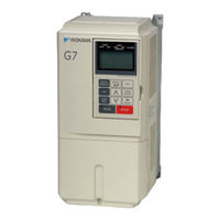
YASKAWA Varispeed IMR-G7A4045 Instruction Manual (541 pages)
General Purpose Inverter (Advanced Vector Control)
Brand:
YASKAWA
| Category:
Inverter
| Size: 21.65 MB
Table of Contents
Safety Information
3
Safety Precautions
4
Warning Information and Position
8
Warranty Information
9
Registered Trademarks
10
Before Reading this Manual
10
Table of Contents
11
Handling Inverters
19
Varispeed G7 Introduction
20
Varispeed G7 Models
20
Confirmations Upon Delivery
21
Checks
21
Nameplate Information
21
Component Names
23
Exterior and Mounting Dimensions
24
Open Chassis Inverters (IP00)
24
Enclosed Wall-Mounted Inverters [NEMA1 (Type 1)]
25
Checking and Controlling the Installation Site
27
Installation Site
27
Controlling the Ambient Temperature
27
Protecting the Inverter from Foreign Matter
27
Installation Orientation and Space
28
Removing and Attaching the Terminal Cover
29
Removing the Terminal Cover
29
Attaching the Terminal Cover
30
Removing/Attaching the Digital Operator and
31
Inverters of 15 Kw or Less
31
Inverters of 18.5 Kw or more
34
Removing and Attaching the Protection Cover
35
Removing the Protection Cover
35
Attaching the Protection Cover
36
Wiring
37
Connections to Peripheral Devices
38
Ground Fault Interrupters, Molded-Case Circuit Breakers, and Magnetic Contactors
40
Precautions When Using Peripheral Devices
42
Selecting and Installing a Ground Fault Interrupter or Molded-Case Circuit Breaker
42
Using a Magnetic Contactor on the Power Supply Side
42
Using a Magnetic Contactor on the Motor Side
42
Installing a Thermal Overload Relay
42
Power Factor Improvement (Elimination of Phase-Advancing Capacitors)
43
Radio Wave Interference
43
Wire Thickness and Wiring Distance
43
Connection Diagram
44
Terminal Block Configuration
46
Wiring Main Circuit Terminals
47
Applicable Wire Sizes and Closed-Loop Connectors
47
Main Circuit Terminal Functions
54
Main Circuit Configurations
55
Standard Connection Diagrams
56
Wiring the Main Circuits
57
Wiring Control Circuit Terminals
65
Wire Sizes and Closed-Loop Connectors
65
Control Circuit Terminal Functions
67
Control Circuit Terminal Connections
71
Control Circuit Wiring Precautions
72
Wiring Check
73
Checks
73
Installing and Wiring Option Boards
74
Option Board Models and Specifications
74
Installation
75
PG Speed Control Board Terminals and Specifications
76
Wiring
78
Wiring Terminal Blocks
81
Selecting the Number of PG (Encoder) Pulses
82
Digital Operator and Modes
84
Digital Operator
85
Digital Operator Display
85
Digital Operator Keys
85
Modes
88
Inverter Modes
88
Switching Modes
89
Drive Mode
90
Quick Programming Mode
91
Advanced Programming Mode
93
Verify Mode
96
Autotuning Mode
97
Trial Operation
99
Overview of Trial Operation Procedure
100
Trial Operation Procedures
101
Setting the Power Supply Voltage Jumper (400 V Class Inverters of 55 Kw or Higher)
101
Power on
101
Checking the Display Status
102
Setting the Control Method
102
Settings for the Control Methods
104
Basic Settings
105
Autotuning
107
Application Settings
125
Load Operation
125
Loaded Operation
125
Check and Recording User Constants
126
Adjustment Suggestions
127
User Constants
133
User Constant Descriptions
134
Description of User Constant Tables
134
Digital Operation Display Functions and Levels
135
User Constants Settable in Quick Programming Mode
136
User Constant Tables
141
A: Setup Settings
141
B: Application Constants
143
C: Autotuning Constants
154
D: Reference Constants
160
E: Motor Constant Constants
166
F: Option Constants
172
H: Terminal Function Constants
179
L: Protection Function Constants
191
N: Special Adjustments
202
O: Digital Operator Constants
206
T: Motor Autotuning
210
U: Monitor Constants
211
Factory Settings that Change with the Control Method (A1-02)
222
Factory Settings that Change with the Inverter Capacity (O2-04)
225
Carrier Frequency Constant Settings that Change with the Inverter Capacity (O2-04) and Control Method (A1-02) (Applicable for PRG 1042 and Later)
229
Constant Settings by Function
234
Frequency Reference
235
Selecting the Frequency Reference Source
235
Using Multi-Step Speed Operation
238
Varispeed G7 Function Block
241
Run Command
243
Selecting the Run Command Source
243
Stopping Methods
245
Selecting the Stopping Method When a Stop Command Is Sent
245
Using the DC Injection Brake
249
Using an Emergency Stop
250
Acceleration and Deceleration Characteristics
251
Setting Acceleration and Deceleration Times
251
Accelerating and Decelerating Heavy Loads (Dwell Function)
255
Preventing the Motor from Stalling During Acceleration (Stall Prevention During Acceleration Function)
256
Preventing Overvoltage During Deceleration (Stall Prevention During Deceleration Function)
258
Preventing Overvoltage by Automatically Reducing the Regenerative Torque Limit (Overvoltage Inhibit Function, PRG 102 Only)
259
Adjusting Frequency References
261
Adjusting Analog Frequency References
261
Operation Avoiding Resonance (Jump Frequency Function)
264
Adjusting Frequency Reference Using Pulse Train Inputs
266
Speed Limit (Frequency Reference Limit Function)
267
Improved Operating Efficiency
269
Reducing Motor Speed Fluctuation (Slip Compensation Function)
269
Compensating for Insufficient Torque at Startup and Low-Speed Operation (Torque Compensation)
271
Starting Torque Compensation
273
Hunting-Prevention Function
274
Stabilizing Speed (Speed Feedback Detection Function)
275
Machine Protection
276
Reducing Noise and Leakage Current
276
Limiting Motor Torque (Torque Limit Function)
280
Preventing Motor Stalling During Operation
283
Changing Stall Prevention Level During Operation Using an Analog Input
284
Using Frequency Detection: L4-01 to L4-05
284
Detecting Motor Torque
287
Changing Overtorque and Undertorque Detection Levels Using an Analog Input
290
Motor Overload Protection
291
Setting Motor Protection Operation Time
293
Motor Overheating Protection Using PTC Thermistor Inputs
294
Limiting Motor Rotation Direction
296
Continuing Operation
297
Restarting Automatically after Power Is Restored
297
Speed Search
298
Continuing Operation at Constant Speed When Frequency Reference Is Lost
305
Restarting Operation after Transient Fault (Auto Restart Function)
306
Operation Selection after Cooling Fan Fault
307
Inverter Protection
308
Input Terminal Functions
310
Temporarily Switching Operation between Digital Operator and Control Circuit Terminals
310
Blocking Inverter Outputs (Baseblock Commands)
311
Stopping Acceleration and Deceleration (Acceleration/Deceleration Ramp Hold)
312
Raising and Lowering Frequency References Using Contact Signals (UP/DOWN)
313
Accelerating and Decelerating Constant Frequencies in the Analog References (+/- Speed)
316
Hold Analog Frequency Using User-Set Timing
317
Switching Operations between a Communications Option Board and Control Circuit Terminals
317
Jog Frequency Operation Without Forward and Reverse Commands (FJOG/RJOG)
318
Stopping the Inverter by Notifying Programming Device Errors to the Inverter (External Fault Function)
319
Output Terminal Functions
320
Monitor Constants
322
Using the Analog Monitor Constants
322
Using Pulse Train Monitor Contents
324
Individual Functions
326
Using MEMOBUS Communications
326
Using the Timer Function
340
Using PID Control
341
Energy-Saving
350
Setting Motor Constants
352
Setting the V/F Pattern
355
Torque Control
362
Speed Control (ASR) Structure
371
Increasing the Speed Reference Response (Feed Forward Control)
377
Droop Control Function
378
Zero-Servo Function
380
Digital Operator Functions
383
Setting Digital Operator Functions
383
Copying Constants
386
Prohibiting Writing Constants from the Digital Operator
391
Setting a Password
391
Displaying User-Set Constants Only
392
Options
393
Performing Speed Control with PG
393
Using Digital Output Boards
397
Using an Analog Reference Board
399
Using a Digital Reference Board
400
Using Inverters for Elevating Machines
405
Brake ON/OFF Sequence
405
Using Inverters for Elevating Machines
406
Stall Prevention During Deceleration
407
Autotuning
407
Braking Resistor Overheating Protection
407
Momentary Power Loss Restart
407
Torque Limit
407
I/O Open-Phase Protection and Overtorque Detection
408
External Baseblock Signal
408
Acceleration/Deceleration Time
408
Magnetic Contactor on the Inverter's Output-Side
408
Control-Related Adjustments
409
Reducing Shock During Elevating Machine Start, Stop, Acceleration, and Deceleration
411
Confirming Startup Current and Reducing Carrier Frequency
414
Overvoltage Inhibit Function
415
Current Alarm Function
416
Peak Hold Current Monitoring Function
417
Maintenance Timer Display Function
418
Settings Required to Use Maintenance Timer Display Function
418
Settings Required after Replacement of Cooling Fan or Circuit Board
419
Troubleshooting
420
Protective and Diagnostic Functions
421
Fault Detection
421
Alarm Detection
435
Operation Errors
440
Errors During Autotuning
442
Errors When Using the Digital Operator Copy Function
443
Troubleshooting
445
If Constant Constants Cannot be Set
445
If the Motor Does Not Operate
446
If the Direction of the Motor Rotation Is Reversed
449
If the Motor Does Not Put out Torque or if Acceleration Is Slow
449
If the Motor Operates Higher than the Reference
449
If the Slip Compensation Function Has Low Speed Precision
450
If There Is Low Speed Control Accuracy at High-Speed Rotation in Open-Loop Vector Control Method
450
If Motor Deceleration Is Slow
450
If the Motor Overheats
451
If There Is Noise When the Inverter Is Started or from an am Radio
452
If the Ground Fault Interrupter Operates When the Inverter Is Run
452
If There Is Mechanical Oscillation
452
If the Torque Generated for the Motor Is Insufficient (Insufficient Power)
454
Large Compared to that at Medium and High Speeds
454
If Shock Occurs Near the Speed Estimator Switching Frequency in Open-Loop Vector 2 Control (PRG 102 Only)
454
If Torque Ripple Occurs at very Low Speeds in Open-Loop Vector 2 Control (PRG 102 Only)
455
If the Motor Rotates Even When Inverter Output Is Stopped
455
If OV Is Detected When the Fan Is Started, or Fan Stalls
455
If Output Frequency Does Not Rise to Frequency Reference
455
Acoustic Noise from the Motor
456
If Motor Overload (OL1) Is Detected Even Though the Current Is below the Motor Rated Current
456
Maintenance and Inspection
457
Maintenance and Inspection
458
Outline of Warranty
458
Daily Inspection
458
Periodic Inspection
458
Storage Guidelines
459
Periodic Maintenance of Parts
460
Procedure for Adjusting Constants after Replacement of Control Board
460
Types and Number of Cooling Fans Used in the Drive
463
Cooling Fan Replacement Outline
464
Circulation Fan Replacement Outline
474
Removing and Mounting the Control Circuit Terminal Board
480
Specifications
481
Standard Inverter Specifications
482
Specifications by Model
482
Common Specifications
484
Specifications of Options and Peripheral Devices
486
Appendix
489
Varispeed G7 Control Methods
490
Control Methods and Features
490
Control Methods and Applications
492
Inverter Application Precautions
494
Selection
494
Installation
495
Settings
495
Handling
496
Motor Application Precautions
497
Using the Inverter for an Existing Standard Motor
497
Using the Inverter for Special Motors
498
Power Transmission Mechanism (Speed Reducers, Belts, and Chains)
498
Conformance to UL Standard
499
Conformance to CE Markings
501
CE Markings
501
Requirements for Conformance to CE Markings
501
Precautions for Korean Radio Waves Act
508
한국 전파법에 관한 주의사항
509
China Rohs Compliance
510
Information on Hazardous Substances in this Product
510
对应中国 Rohs 指令
511
本产品中含有有害物质的信息
511
Wiring Examples
512
Using a Braking Resistor Unit
512
Using a Braking Unit and Braking Resistor Unit
513
Using Braking Units in Parallel
514
Using a Braking Unit and Three Braking Resistor Units in Parallel
515
Using a VS Operator
516
Using Transistors for Input Signals and a 0-V Common in Sinking Mode with an Internal Power Supply
517
Using Transistors for Input Signals and a +24-V Common in Sourcing Mode
518
Using Transistors for Input Signals and a 0-V Common in Sinking Mode with an External Power Supply
519
Using Contact and Open Collector Outputs
520
User Constants
521
Control Block Diagrams
530
Control Block Diagrams for Control Methods
530
Troubleshooting Record Sheet
533
Revision History
537
Advertisement
Advertisement
Related Products
Yaskawa Varispeed-606PC3
YASKAWA Varispeed G7
YASKAWA Varispeed CIMR-G7A
YASKAWA Varispeed-676
Yaskawa VARISPEED-626M5
Yaskawa VARISPEED-626MR5
YASKAWA Varispeed 606PC3
YASKAWA varispeed G7 CIMR-G7B series
YASKAWA Varispeed L7
YASKAWA VARISPEED-656MR5
YASKAWA Categories
Controller
DC Drives
Servo Drives
Robotics
Control Unit
More YASKAWA Manuals
Login
Sign In
OR
Sign in with Facebook
Sign in with Google
Upload manual
Upload from disk
Upload from URL