Sign In
Upload
Manuals
Brands
Yamaha Manuals
Outboard Motor
EK25BMH
Yamaha EK25BMH Manuals
Manuals and User Guides for Yamaha EK25BMH. We have
3
Yamaha EK25BMH manuals available for free PDF download: Rigging Manual, Service Manual
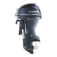
Yamaha EK25BMH Rigging Manual (329 pages)
Brand:
Yamaha
| Category:
Outboard Motor
| Size: 11.2 MB
Table of Contents
Table of Contents
5
Engine Oil Reminder Tag (4-Stroke Engines)
10
Top Cover Pictograph Description
10
Uncrating Procedure (for Typical Steel Frame)
11
Mounting the Outboard Motor
13
Water Level Guideline (4-Stroke Engines)
17
Adjusting Twin Engines
18
Max. Boat Speed Estimation
18
Mounting the Remote Oil Tank
19
Remote Oil Tank Dimensions
19
Notice for Mounting the Remote Oil Tank
19
Outboard Motor Dimensions
20
Overall Dimension Items
20
Overall Dimensions (4-Stroke)
22
Overall Dimensions (2-Stroke)
31
Clamp Bracket Dimension Items
37
Clamp Bracket Dimensions
38
Propellers
65
Propeller Specifications
66
Propeller Types
66
Propeller Identification
69
2014 Propeller Applications
70
Standard Propeller
70
STANDARD PROPELLERS (Shift Dampener System [SDS])
76
Dual Thrust Propellers
77
Weedless Propellers
78
Reliance Series Propellers (Std)
78
RELIANCE SERIES PROPELLERS (Shift Dampener System [SDS])
79
Saltwater Series Propellers
80
Saltwater Series II Propellers (Std)
81
SALTWATER SERIES II PROPELLERS (Shift Dampener System [SDS])
82
Saltwater Series Hs4 Propellers (Std)
83
SALTWATER SERIES HS4 PROPELLERS (Shift Dampener System [SDS])
83
SALTWATER SERIES XL PROPELLERS (Shift Dampener System [SDS])
84
SALTWATER SERIES XL4 PROPELLERS (Shift Dampener System [SDS])
84
Vmax Series Propellers
85
Performance Series Propellers
85
High Performance Series Propellers
86
Propeller Selection
70
Wot Operation Range Table
87
Remote Controls
89
Remote Control Types and Applications
90
Remote Switch Types and Applications
106
Remote Control Cables
121
Remote Control Attachment Kit
123
Steering Hook
127
Steering Guide Attachment Kit
130
Tie-Bar Kit
132
Conventional Wire Harness
133
Digital Electronic Remote Control Wire Harness
134
Tiller Handles
139
6X4 Multi-Function Tiller Handle
140
Multi-Function Tiller Handle Kit (for Us)
140
Tiller Handle Kit Contents
141
Wiring Diagram (for Us)
149
Exploded Diagram (for Us)
150
Multi-Function Tiller Handle Kit (for Japan)
151
Wiring Diagram (for Japan)
153
Exploded Diagram (for Japan)
154
Multi-Function Tiller Handle Contents (for Others)
155
Tiller Handle Grommet Description
155
Multi-Function Tiller Handle Kit (for Eu & Anz)
156
Handle Immobilizer Kit Contents
160
Wiring Diagram (for Eu & Anz)
161
Steering Friction Contents
162
Conventional Gauge (6Y5 & 6Y7)
165
Mounting the Meters
168
Meter Mounting Procedure
168
Analog Gauge Illumination (6Y7 Type)
168
Analog Tachometer
169
Analog Tachometer Applications
169
Analog Tachometer Dimensions
170
Pole Number Set up
170
Digital Tachometer
171
Digital Tachometer Applications
171
Digital Tachometer Dimensions
171
Pole Number Set up
172
Speedometer
173
Speedometer Types and Applications
173
Speedometer Dimensions
174
Water Pressure Damper (Op)
174
Speedometer Tube Routing
175
Digital Speedometer Set up
175
Fuel Management Gauge
176
Fuel Management Gauge Types and Applications
176
Fuel Management Gauge Dimensions
177
Fuel Sensor Installation
178
Wiring Description
179
Fuel Management Gauge Set up
181
Fuel Mgt Gauge with Speedometer Set up
181
Analog Trim Meter
182
Analog Trim Meter Applications
182
Analog Trim Meter Dimensions
182
Trim Sensor Adjustment
182
Coolant Pressure Meter
183
Coolant Pressure Meter Applications
183
Coolant Pressure Meter Dimensions
183
Coolant Press. Attachment Installation
183
Coolant Temp. Meter
184
Coolant Temp. Meter Types and Applications
184
Coolant Temp. Meter Dimensions
184
Coolant Press. Attachment And/Or Coolant Temp
185
Routing Coolant Temp. Lead
186
Routing the Coolant Press. Tube
186
Coolant Temp. Sensor And/Or Coolant Press
187
(For 4-Stroke Models)
187
Routing the Coolant Temp. Lead & Coolant Press. Tube
189
Sensor/Attachment Installation and Routing
190
Hour Meter
191
Hour Meter Applications
191
Hour Meter Dimensions
191
Wiring the Mechanical Hour Meter
192
Wiring the Digital Hour Meter
192
Voltage Meter
193
Voltage Meter Types and Applications
193
Voltage Meter Dimensions
193
Wiring the Voltage Meter
193
Fuel Meter
194
Fuel Meter Types and Applications
194
Fuel Meter Dimensions
194
Wiring the Fuel Meter
194
Charge Warning Unit
195
Charge Warning Unit Types and Applications
195
Wiring the Charge Warning Unit
195
Wire Harnesses
196
Remote-Oil Tank Harness
196
Additional Accessory Lead
196
Meter Harness
197
Trim Meter Lead
198
Trim and Oil Lead
198
Combination Trim and Oil Lead
198
Conversion Harness 1
199
Fuel Management Gauge Harness
199
Lighting Coil Extension Harness
199
Rectifier Kit
199
Wiring Diagrams
200
Wire Color Code
200
Digital Meter (6Y5)
201
Analog Meter (6Y7)
206
INTERCHANGEABILITY between TACHOMETER and ENGINE (up to 2006 and after 2007)
208
Rigging Grommet Description
211
Digital Network Gauge (6Y8)
215
Digital Network Gauge Compatible Models
216
Digital Network Gauge Application
216
Square Style Gauge Application
216
Digital Network Gauge Dimensions
217
Round Style Gauge Application
217
Square Style Gauge Dimensions
217
Round Style Gauge Dimensions
218
Optional Equipment
219
Multi-Sensor Application
219
Fitting Plate
219
Speed Sensor Kit
220
Coolant Pressure Sensor Kit
220
Speed/Coolant Pressure Sensors Kit
221
Wire Harness
222
Main Bus Wire
222
Pigtail Bus Wire
222
System Power Supply Wire
222
Immobilizer Power Distribution Wire 1
222
Network Hub
223
Fuel Tank / Gps Wire
223
Optional Equipment
224
Nmea2000 Gateway
224
Analog Gauge Interface (If)
224
Immobilizer Unit
225
Network Wiring Diagrams
226
FUEL INJECTED F30-F250 [Mechanical RC] & HPDI ENGINES
226
Initial Gauge Setup
230
Setting for Gauge When 6Y9 Multi-Sensor Is Connected
230
Troubleshooting
231
Nmea0183 Compatible Equipment Connection
232
Basic Requirements
232
Digital Network Gauge (6Y8) Function Table
233
Digital Network Premium Gauge (6Y9)
234
Digital Network Premium Gauge Compatible Models
236
Digital Network Premium Gauge Application
236
Digital Network Premium Gauge Dimensions
237
Premium Color Gauge Dimensions
237
Optional Equipment
238
Transom Multi-Sensor (6Y9)
238
Immobilizer Unit
238
Nmea2000 Gateway
239
Analog Gauge Interface (If)
239
Speed Sensor Kit
240
Coolant Pressure Sensor Kit
240
Network Hub
241
Wire Harness
242
Main Bus Wire
242
Pigtail Bus Wire
242
Gps Wire
242
Tank Wire
242
System Power Supply Wire
243
System Power Distribution Wire
243
Conversion Harness
244
Conversion Harness 1
244
Conversion Harness 4
244
Conversion Harness L
245
Twinning Harness
245
Conversion Harness M (for 2Nd Helm)
245
Conversion Harness N (for 2Nd Helm)
245
Conversion Harness P (for 2Nd Helm)
246
Conversion Harness K (for Dual Station)
246
Network Wiring Diagrams
247
SINGLE STATION W/ 6Y9 GAUGE SINGLE ENGINE APPLICATION (6X6 Binnacle Mount Digital Electronic Control)
247
SINGLE STATION W/ 6Y8 GAUGE SINGLE ENGINE APPLICATION (6X6 Binnacle Mount Digital Electronic Control)
249
SINGLE STATION W/ 6Y9 GAUGE SINGLE ENGINE APPLICATION (6X7 Concealed Digital Electronic Control)
251
SINGLE STATION W/ 6Y8 GAUGE SINGLE ENGINE APPLICATION (6X7 Concealed Digital Electronic Control)
253
Single Station W/ 6Y9 Gauge Twin Engine Application
255
Single Station W/ 6Y8 Gauge Twin Engine Application
257
Single Station W/ 6Y9 Gauge Triple Engine Application
259
Single Station W/ 6Y8 Gauge Triple Engine Application
261
Single Station W/ 6Y9 Gauge Quad Engine Application (for F/Lf225Ca, F/Lf250Ca, F/Lf300Ca, F/Lf350Ca/B)
263
Dual Station W/ 6Y9 Gauge Single Engine Application
267
Dual Station W/ 6Y8 Gauge Single Engine Application
269
Dual Station W/ 6Y9 Gauge Twin Engine Application
271
Dual Station W/ 6Y8 Gauge Twin Engine Application
273
Dual Station W/ 6Y9 Gauge Triple Engine Application
275
Dual Station W/ 6Y9 Gauge Quad Engine Application (for F/Lf225Ca, F/Lf250Ca, F/Lf300Ca, F/Lf350Ca/B)
277
Battery
281
Battery
282
Recommended Battery
282
Battery Cable Length
284
Battery Wiring
286
Isolator Equipped Model (above 150Ps Model)
286
Example for Battery Cable Wiring (Twin Engine Application)
287
Recommended Extension Length of Battery Cables
288
Recommended Battery Switch Capacity
292
Battery Charging Capability
292
Appendix
294
Model Name Designation
296
Global Models Identification Code
296
Us & Canada Models Identification (Code)
297
Us & Canada New Models Identification Code
297
Fuel System Vacuum Pressure Standard
298
Fuel Hose Routing Resistance Measuring Method
298
Lowest Vacuum Pressure Standard
299
Portable Fuel Tanks (Typical)
300
Fuel Pipes (Typical)
301
Primary Pump (Typical)
301
Pre-Delivery Inspection (Pdi)
302
Conventional Rigging Kit Contents
303
Digital Tachometer Kit
303
Digital Tachometer and Speedometer Kit
303
Twin-Motor Kit
304
Remote Oil Tank Kit (for 2-Stroke Engine)
305
Digital Network Gauge Rigging Kit Contents
306
Square/Round Style Gauge Rigging Kit Contents for Us and Canada
306
Square Style Gauge Rigging Kit for Europe
306
Round Style Gauge Rigging Kit for Europe
310
Square Style Gauge Rigging Kit for Anz
311
Square Style Gauge Rigging Kit for Japan
313
Round Style Gauge Rigging Kit for Japan
314
Immobilizer Rigging Kit Contents
315
Immobilizer Kit 1 (for Us, Anz, Crb)
315
Immobilizer Kit 2 (for Jpn)
315
Single Engine Gauge Kit for Immobilizer (for Eu, Anz, Jpn, Gen)
315
Twin Engine Gauge Kit for Immobilizer
316
Digital Network Premium Gauge Rigging Kit Contents
317
Twin Engine Premium Gauge Kit
318
Triple Engine Premium Gauge Kit (for Eu, Anz, Gen)
318
Main Helm Sw Panel Twin Engine Kit (for Us, Can)
318
Main Helm Sw Panel Triple Engine Kit (for Us, Can)
319
2Nd Helm Sw Panel Single Engine Kit (for Us, Can)
319
2Nd Helm Sw Panel Twin Engine Kit (for Us, Can)
319
2Nd Helm Sw Panel Triple Engine Kit (for Us, Can)
319
Other Rigging Kit Contents
320
Tilt Limit Switch Kit (for Us, Ca, Eu, Anz, Rus, Jpn)
320
Tilt Limit Switch Kit 2 (for Us, Ca, Eu, Anz, Jp, Rus, Tur)
320
Tilt Limit Switch Kit 3 (for Us, Ca, Eu, Anz, Jp, Rus, Tur)
321
Tilt Limit Switch Kit 4 (for Us, Ca, Eu, Anz, Jp, Rus, Tur)
321
Lighting Coil Kit (for Eu, Ca, Jpn)
322
2014 Year Models Manufacture Starting Serial Numbers
323
Advertisement
Yamaha EK25BMH Service Manual (230 pages)
Outboard Motor Yamaha EK25BMH
Brand:
Yamaha
| Category:
Outboard Motor
| Size: 8.42 MB
Table of Contents
Gen Info
9
How to Use this Manual
3
General Information
6
Table of Contents
9
Chapter 1
10
Identification
10
Serial Number
10
Starting Serial Numbers
10
Safety While Working
11
Fire Prevention
11
Ventilation
11
Self-Protection
11
Oils, Greases and Sealing Fluids
11
Good Working Practices
12
Disassembly and Assembly
13
Special Tools
14
Measuring
14
17 Shimming Plate
15
Removing and Installing
16
Features and Benefits
18
Power Unit
18
Ignition System
19
Cooling System
20
Tiller Handle
22
Bracket and Bottom Cowling
23
Table of Contents
25
Chapter 2
27
General Specifications
27
Maintenance Specifications
28
Power Unit
28
Lower Unit
30
Electrical
31
Dimensions
33
Tightening Torques
36
Specified Torques
36
Recoil Starter
36
General Torques
37
Chapter 3 Periodic Check and Adjustment
39
Maintenance Interval Chart
40
Fuel System
41
Checking the Fuel Line
41
Checking the Fuel Filter
42
Checking the Fuel Pump
42
Checking the Fuel Joint
42
Top Cowling
41
Checking the Top Cowling Fit
41
Control System
43
Adjusting the Ignition Timing
43
Adjusting the Engine Idle Speed
54
Adjusting the Start-In-Gear Protection Device
56
Power Unit
57
Measuring the Compression Pressure
57
Cooling System
58
Checking the Cooling Water Discharge
58
Lower Unit
58
Checking the Gear Oil Level
58
Changing and Checking the Gear Oil
58
Checking the Lower Unit (for Air Leaks)
59
General
60
Checking the Anode
60
Checking the Spark Plugs
61
Checking the Propeller
62
Checking Bolts and Nuts
62
Lubrication Points
63
Table of Contents
65
Chapter 4
66
Fuel Joint, Fuel Filter, and Fuel Pump
66
Removing the Fuel Joint, Fuel Filter and Fuel Pump
66
Assembling the Fuel Filter
68
Checking the Fuel Filter
68
Checking the Fuel Joint
68
Disassembling the Fuel Pump
69
Fuel Pump
69
Checking the Fuel Pump
71
Assembling the Fuel Pump
72
Carburetor
74
Removing the Carburetor
74
Disassembling the Carburetor
75
Checking the Carburetor
81
Assembling the Carburetor
82
Installing the Carburetor
85
Chapter 5 Recoil Starter
88
Removiing the Recoil Starter
90
Disassembling the Recoil Starter
91
Checking the Recoil Starter
93
Assembling the Recoil Starter
95
Installing the Recoil Starter
98
Flywheel Magnet
99
Removiing the Flywheel Magnet
99
Installing the Flywheel Magnet
100
Power Unit
101
Disconnecting the Leads and Stays
101
Removing the Power Unit
103
Magnet Base and Control Lever
104
Removing the Magnet Base and Magnet Control Lever
104
Intake Manifold and Reed Valves
106
Removing the Intake Manifold and Reed Valves
106
Checking the Reed Valves
107
Installing the Intake Manifold
107
Cylinder Head
108
Removing the Cylinder Head
108
Checking the Cylinder Head
109
Checking the Thermostat
110
Installing the Cylinder Head and Cylinder Head Cover
111
Installing the Thermostat
111
Exhaust Cover
112
Removing the Exhaust Cover
112
Checking the Exhaust Cover
113
Installing the Exhaust Cover
113
Crankcase
114
Removing the Crankcase
114
Assembling the Oil Seal Housing
115
Iinstalling the Crankcase
115
Crankshaft and Cylinder Body
117
Removing the Crankshaft and Cylinder Body
117
Checking the Cylinder Body
118
Checking the Piston
119
Calculating the Piston-To-Cylinder Clearance
120
Checking the Piston Pins and Small-End Bearings
121
Checking the Pisotn Rings
122
Checking the Crankshaft
123
Installing the Piston and Piston Rings
126
Installing the Crankshaft and Piston
126
Checking the Anode
127
Crank Shaft
128
Disassembling the Crankshaft
128
Removing the Crankshaft Bearing
130
Assembling the Crankshaft
133
Installing Crankshaft Bearing
139
Checking the Crankshaft
140
Lowr Chapter 6 Lower Unit
142
Chapter 6 Lower Unit
144
Removing the Lower Unit
144
Checking the Propeller
146
Installing the Propeller
146
Installing the Trim Tab
146
Removing the Propeller
146
Water Pump
147
Removing the Water Pump
147
Checking the Water Pump Housing
148
Checking the Impeller and Insert Cartridge
148
Checking the Woodruff Key
148
Installing the Impeller and Water Pump Housing
148
Shift Rod
149
Removing the Shift Rod
149
Propeller Shaft Housing
150
Removing the Propeller Shaft Housing
150
Disassembling the Propeller Shaft Housing
151
Disassembling the Propeller Shaft
152
Removing the Propeller Shaft Housing
153
Disassembling the Propeller Shaft Housing
153
Checking the Reverse Gear
154
Checking the Bearing
154
Checking the Propeller Shaft Housing
154
Assembling the Propeller Shaft Housing
155
Checking the Dog Clutch
156
Checking the Propeller Shaft
156
Checking the Shift Plunger
156
Checking the Shift Spring
156
Drive Shaft
157
Removing the Drive Shaft
157
Removing the Drive Shaft Bearing
158
Disassembling the Forward Gear
158
Checking the Pinion and Forward Gear
159
Checking the Drive Shaft
159
Checking the Bearings
159
Assembling the Forward Gear
159
Installing the Drive Shaft Bearing
159
Installing the Drive Shaft
159
Lower Case
161
Disassembling the Lower Case
161
Checking the Drive Shaft Sleeve
162
Checking the Needle Bearing
163
Assembling the Lower Case
163
Shimming
164
Selecting the Pinion Shims
165
Selecting the Forward Gear Shims
167
Selecting the Reverse Gear Shims
169
Backlash
171
Measuring the Forward Gear Backlash
171
Measuring the Reverse Gear Backlash
172
Bracket Unit
175
Chapter 7
176
Disassembling the Steering Handle
176
Steering Handle
176
Assembling the Steering Handle
178
Checking the Steering Handle
178
Bottom Cowling
180
Removing the Bottom Cowling
180
Checking the Bottom Cowling
182
Installing the Bottom Cowling
182
Shift Actuator
183
Disassembling the Shift Actuator
183
Removing the Bracket
186
Checking the Shift Actuator
186
Assembling the Shift Actuator
187
Upper Case
189
Removing the Upper Case
189
Checking the Upper Case
191
Installing the Upper Case
191
Disassembling the Upper Case
192
Checking the Exhaust Manifold
193
Assembling the Upper Case
193
Steering Arm
194
Removing the Steering Arm
194
Checking the Steering Arm
195
Installing the Steering Arm
195
Clamp Brackets
196
Removing the Clamp Brackets
196
Checking the Clamp Brackets
199
Installing the Clamp Brackets
200
Electrical System
203
Chapter 8
204
Electrical Component
204
Electrical Components Analysis
205
Digital Circuit Tester
205
Measuring the Peak Voltage
205
Peak Voltage Adapter
205
Measuring a Low Resistance
206
Ignition System
207
Wiring Diagram
207
Checking the Spark Plugs
208
Checking the Ignition Spark Gap
208
Checking the Spark Plug Caps
209
Removing the Spark Plug Caps (Standard Type)
209
Installing the Spark Plug Caps (Standard Type)
209
Checking the Ignition Coils
210
Checking the Charge Coil
211
Checking the Pulser Coil
212
CDI Unit
213
Checking the CDI Unit
214
Ignition Control System
216
Wiring Diagram
216
Checking the Engine Stop Switch
217
Charging System
218
Wiring Diagram
218
Checking the Lighting Coil
219
Trouble Analysis
221
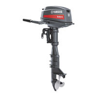
Yamaha EK25BMH Rigging Manual (226 pages)
Brand:
Yamaha
| Category:
Outboard Motor
| Size: 7.75 MB
Table of Contents
Table of Contents
5
Top Cover Pictograph Description
8
Uncrating Procedure (for Typical Steel Frame)
9
Mounting the Outboard Motor
11
Water Level Guideline (4-Stroke Engines)
15
Adjusting Twin Motors
16
Mounting the Remote Oil Tank
16
Remote Oil Tank Dimensions
16
Notice for Mounting the Remote Oil Tank
17
Outboard Motor Dimensions
18
Overall Dimension Items
18
Overall Dimensions (2-Stroke)
20
Overall Dimensions (4-Stroke)
27
Clamp Bracket Dimension Items
34
Clamp Bracket Dimensions
35
Propellers
59
Propeller Specifications
60
Propeller Types
60
Propeller Identification
62
2009 Propeller Applications
63
Standard, Dual Thrust & Weedless Propellers
63
Reliance Series Propellers
66
Saltwater Series Propellers
67
Saltwater Series Ιι Propellers
67
Saltwater Series Hs4 Propellers
67
Saltwater Series Xl Propellers
68
Vmax Series Propellers
68
Performance Propellers
68
High Performance Propellers
68
Propeller Selection
63
Wot Operation Range Table
69
Remote Controls
71
Remote Control Applications
72
Remote Switch Applications
85
Remote Control Cables
94
Remote Control Attachment Kit
96
Steering Hook
98
Steering Guide Attachment Kit
101
Conventional Wire Harness
103
Digital Electronic Control Wire Harness
105
Tiller Handles
107
6X4 Multi-Function Tiller Handle
108
Multi-Function Tiller Handle Kit (for Us)
108
Wiring Diagram (for Us)
113
Multi-Function Tiller Handle Kit (for Japan)
114
Multi-Function Tiller Handle Contents (for Others)
116
Tiller Handle Grommet Description
116
Steering Friction Contents
117
Conventional Gauge (6Y5 & 6Y7)
119
Mounting the Meters
122
Meter Mounting Procedure
122
Analog Gauge Illumination (6Y7 Type)
122
Analog Tachometer
123
Analog Tachometer Applications
123
Analog Tachometer Dimensions
124
Pole Number Set up
124
Digital Tachometer
125
Digital Tachometer Applications
125
Digital Tachometer Dimensions
125
Pole Number Set up
126
Speedometer
127
Speedometer Applications
127
Speedometer Dimensions
128
Water Pressure Damper (Op)
128
Speedometer Tube Routing
129
Digital Speedometer Set up
129
Fuel Management Gauge
130
Fuel Management Gauge Applications
130
Fuel Management Gauge Dimensions
131
Fuel Sender Installation
132
Wiring Description
133
Fuel Management Gauge Set up
135
Fuel Mgt Gauge with Speedometer Set up
135
Analog Trim Meter
136
Analog Trim Meter Applications
136
Analog Trim Meter Dimensions
136
Trim Sender Adjustment
136
Coolant Pressure Meter
137
Coolant Pressure Meter Applications
137
Coolant Pressure Meter Dimensions
137
Coolant Temp. Meter
138
Coolant Temp. Meter Applications
138
Coolant Temp. Meter Dimensions
138
Coolant Press. Sender And/Or Coolant Temp. Sender Installation (for 2-Stroke Models)
139
Routing Coolant Temp. Lead
139
Routing the Coolant Press. Tube
140
Coolant Press. Sender And/Or Coolant Temp. Sender Installation (for 4-Stroke Models)
140
Sender Installation
142
Routing the Coolant Temp. Lead
142
Coolant Press. Tube
142
Sender Installation and Routing
143
Hour Meter
144
Hour Meter Applications
144
Wiring the Mechanical Hour Meter
145
Wiring the Digital Hour Meter
145
Voltage Meter
146
Voltage Meter Applications
146
Voltage Meter Dimensions
146
Wiring the Voltage Meter
146
Fuel Meter
147
Fuel Meter Applications
147
Fuel Meter Dimensions
147
Charge Warning Unit
148
Charge Warning Unit Applications
148
Wire Harnesses
149
Remote-Oil Tank Harness
149
Additional Accessory Lead
149
Meter Harness
150
Lamp Switch
151
Combination Trim and Oil Lead 1
151
Combination Trim and Oil Lead 2
151
Trim Meter Lead
151
Pt/T Switch Lead Extension
152
Trim and Oil Lead
152
Fuel Management Gauge Harness
152
Lighting Coil Extension Harness
152
Rectifier Kit
152
Wiring Diagrams
153
Wire Color Code
153
Digital Meter
154
Analog Meter (6Y7)
159
Interchangeability between Tachometer and Engine
161
Grommet Description
164
Digital Network Gauge (6Y8)
167
Digital Network Gauge Compatible Model
168
Digital Network Gauge Application
168
Square Style Gauge Application
168
Digital Network Gauge Dimensions
169
Round Style Gauge Application
169
Square Style Gauge Dimensions
169
Round Style Gauge Dimensions
170
Optional Equipments
171
Multi-Sensor Application
171
Fitting Plate
171
Speed Sensor Kit
172
Coolant Pressure Sensor Kit
172
Wire Harness
173
Main Bus Wire
173
Pigtail Bus Wire
173
Fuel Tank / Gps Wire
174
Hub
174
Wiring Diagrams
175
FUEL INJECTED F50-F250 [Mechanical RC] & HPDI ENGINES
175
F350/F300/F250 [Digital Electronic Control]
178
Initial Gauge Setup
183
Troubleshooting
184
Basic Requirements
185
Nmea0183 Compatible Equipments Connection
185
Battery
187
Recommended Battery
188
Battery Cable Length
189
Battery Wiring
190
Isolator Equipped Model (for over 150Ps Model)
190
Recommended Extension Length of Battery Cables
191
Recommended Battery Switch Capacity
193
Appendix
195
Model Name Designation
196
Us & Canada Model Identification
197
New Us & Canada Model Identification Code
197
Fuel System Vacuum Pressure Standard
198
Fuel Hose Routing Resistance Measuring Method
198
Lowest Vacuum Pressure Standard
199
Portable Fuel Tanks (Typical)
200
Fuel Pipes (Typical)
200
Pre-Delivery Inspection (Pdi) Checks
201
Conventional Rigging Kit Contents
202
Digital Tachometer Kit
202
Digital Tachometer and Speedometer Kit
202
Twin-Motor Kit
203
Remote Oil Tank Kit (for 2-Stroke Engine)
204
Digital Network Gauge Rigging Kit Contents
205
Square Style Gauge Rigging Kit for Us & Canada
205
Round Style Gauge Rigging Kit for Us & Canada
207
Square Style Gauge Rigging Kit for Europe
209
Round Style Gauge Rigging Kit for Europe
213
Transom Rigging Kit for Europe
215
Square Style Gauge Rigging Kit for Anz
216
Square Style Gauge Rigging Kit for Japan
217
Round Style Gauge Rigging Kit for Japan
218
2009 Manufacturing Start Serial Number
219
Advertisement
Advertisement
Related Products
Yamaha EK25CMH
Yamaha EK40G
Yamaha EK40J
Yamaha EK8DMH
Yamaha EK15DMH
Yamaha EK9.9DMH
Yamaha EK15PMH
Yamaha EK9.9JMH
Yamaha EK40GMH
Yamaha EK40JMH
Yamaha Categories
Motorcycle
Musical Instrument
Electronic Keyboard
Receiver
Amplifier
More Yamaha Manuals
Login
Sign In
OR
Sign in with Facebook
Sign in with Google
Upload manual
Upload from disk
Upload from URL