Sign In
Upload
Manuals
Brands
Protech Systems Manuals
Touch terminals
PA-6322
Protech Systems PA-6322 Manuals
Manuals and User Guides for Protech Systems PA-6322. We have
2
Protech Systems PA-6322 manuals available for free PDF download: User Manual, Quick Start Manual
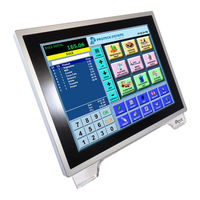
Protech Systems PA-6322 User Manual (304 pages)
15" POS Terminal Powered By Intel Celeron J1900 Quad-Core
Brand:
Protech Systems
| Category:
Touch terminals
| Size: 22.87 MB
Table of Contents
Table of Contents
4
1 Introduction
12
About this Manual
13
POS System Diagrams
14
Panel PC
14
Easy Stand
15
Normal Stand
16
PRINTER Stand
17
System Specifications
19
Optional Accessories
21
Safety Precautions
25
2 System Configuration
26
Function Buttons and I/O Ports
26
System External I/O Ports Diagram & Pin Assignment
27
DC-IN Port
28
Power Button
28
VGA Port
28
COM Port
29
USB Port
29
LAN Port
30
2Nd Display Power Port
31
Cash Drawer Port
31
Printer Power Port (Optional)
31
Main Board Component Location & Jumper Settings
32
Figure 2-1. PB-6722 Main Board Component Location
32
Jumper & Connector Quick Reference Table
34
Setting Jumpers
35
Setting Main Board Connectors and Jumpers
37
COM, Cash Drawer Port Voltage Selection
37
COM Connectors
38
I-Button Connector
38
COM2 & I-Button Function Selection
38
Cash Drawer Control Selection
39
USB Connector
42
LED Connector
42
Speaker Connector
43
Power Connector
43
Inverter Connector
43
Touch Panel Connector
44
Reserved Connectors
44
Panel Resolution Selection
45
Mini PCIE USB Selection
45
MSR / Card Reader Connector
46
LVDS Connector
47
Touch Panel Signal Interface Selection
48
SATA & SATA Power Connector
49
Update BIOS Settings
50
Clear CMOS Data Selection
50
LVDS Link (JP16)
51
LVDS Voltage Selection (JP17)
51
Panel Enable (JP20)
52
Mini-Pcie / Msata Connector
52
Printer Board Component Locations & Pin Assignment
53
Printer Board: PDAC-3100
53
Jumper & Connector Quick Reference Table
54
Setting Printer Board Connectors and Jumpers: PDAC-3100
55
Power Supply Connector
55
RS-232 Interface Connector
55
Auto-Cutter Connector
56
USB Connector
56
Thermal Head/Motor/Sensor Connector
57
Terminal Assignment Connector
59
Printer Board: MB-1030 Series
60
Figure 2-3. MB-1030 Printer Board Component Locations
60
Auto-Cutter Connector
61
Jumper & Connector Quick Reference Table
61
Paper-Near-END Sensor Connector
61
Power Supply Connector
61
RS-232 Interface Connector
61
Thermal Head/Motor/Sensor Connector
61
USB Interface Connector
61
Terminal Assignment Connector
66
Printer Board: MB-1011 & MB-1013
67
Figure 2-4. MB-1011 & MB-1013 Printer Board Component Locations
67
Jumper & Connector Quick Reference Table
68
Setting Printer Board Connectors and Jumpers: MB-1011
69
Power Supply Connector
69
RS-232 Interface Connector
69
Auto-Cutter Connector
70
Thermal Head/Motor/Sensor Connector
70
Terminal Assignment Connector
72
USB Interface Connector
72
VFD Board Component Locations & Pin Assignment
73
VFD Board: MB-4103, LD720
73
Figure 2-5. MB-4103 & LD720 VFD Board Component Locations
73
Jumper & Connector Quick Reference Table
74
Setting MB-4103 & LD720 VFD Board Connectors and Jumpers
75
Power Switch Selection
75
Serial Interface Connector
76
MSR Board Component Locations & Pin Assignment
77
ID Tech
77
Main Connector
77
Information Button Reader
78
Output Connector
78
Mb-3012
78
3 Software Utilities
80
Driver
81
Introduction
81
API Package Folder
81
Driver Folder
81
Readme
81
User Manual Folder
81
Intel ® Chipset Software Installation Utility
82
Installing Intel ® Chipset Driver
82
Introduction
82
VGA Driver Utility
83
Installing VGA Driver
83
LAN Driver Utility
83
Installing LAN Driver
83
Sound Driver Utility
84
Installing Sound Driver
84
Touchscreen Driver Utility
84
Installing Touchscreen Driver
84
Fingerprinter Driver Utility (Optional)
85
Installing Fingerprinter Driver
85
RFID Module Driver Utility (Optional)
85
Installing RFID Module Driver
85
Wireless Module Driver Utility (Optional)
86
Installing Wireless Driver
86
Embedded Peripheral Devices
87
Printer Board: MB-1030
87
Commands
87
OPOS Printer Driver
134
Vfd: Mb-4103 (Rs-232)
143
Commands List
143
OPOS Driver
144
Msr: Mb-3102 (Ps/2)
148
OPOS Driver
148
Msr: Giga-Tms Mjr243 (Rs-232)
156
Commands List
156
OPOS MSR Register
158
OPOS MSR Tester
167
Api
171
API Package Content
171
API Procedure
172
Cash Drawer
175
Watchdog
176
API Function
177
Cash Drawer Function
177
Watch Dog Function
178
BIOS Operation
179
BIOS Setup
179
Figure 3-1. Extensible Firmware Interface Diagram
179
Accessing Setup Utility
180
Figure 3-2. POST Screen with AMI Logo
180
Figure 3-3. BIOS Setup Menu Initialization Screen
181
Figure 3-4. BIOS Main Menu
182
Main
182
Advanced
183
Figure 3-5. BIOS Advanced Menu
183
Acpi Settings
184
Figure 3-6. ACPI Settings Screen
185
Figure 3-7. F81866 Super IO Configuration Screen
186
Figure 3-8. Serial Port 1 Configuration Screen
187
Figure 3-9. Serial Port 2 Configuration Screen
189
Figure 3-10. Serial Port 3 Configuration Screen
190
Figure 3-11. Serial Port 4 Configuration Screen
191
Figure 3-12. Parallel Port Configuration Screen
193
Figure 3-13. Hardware Monitor Screen
194
Figure 3-14. F81866 Watchdog Screen
196
Figure 3-15. CPU Configuration Screen
197
Figure 3-16. Socket 0 CPU Information Screen
198
Figure 3-17. IDE Configuration Screen
199
Figure 3-18. os Selection Screen
201
Figure 3-19. CSM Configuration Screen
202
Figure 3-20. USB Configuration Screen
204
Chipset
206
Figure 3-21. Chipset Menu Screen
206
Figure 3-22. North Bridge Menu Screen
207
Figure 3-23. LCD Control Screen
208
Figure 3-24. South Bridge Screen
209
Figure 3-25. Security Menu Screen
210
Security
210
Boot
211
Figure 3-26. Boot Menu Screen
211
Figure 3-27. Save & Exit Menu Screen
212
Save & Exit
212
Configuring Watchdog Timer
213
Update Procedure
216
Interrupt Map
220
Resource Map
220
I/O Map
225
DMA Channels Map
227
Memory Map
228
Appendix A System Diagrams
230
Easy Maintenance_Hdd
231
Easy Maintenance_Memory
233
Easy Maintenance_Mainboard
238
Exploded Diagram for Stand
260
EXPLODED DIAGRAM for Printer Module
276
Thermal Printer
277
EXPLODED DIAGRAM for Peripheral Devices
287
EXPLODED DIAGRAM for Packing
298
EXPLODED DIAGRAM for Spare Parts
302
Advertisement
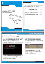
Protech Systems PA-6322 Quick Start Manual (12 pages)
Brand:
Protech Systems
| Category:
Touch terminals
| Size: 17.4 MB
Advertisement
Related Products
Protech Systems PA-6822
Protech Systems PA-3222
Protech Systems PA-3122
Protech Systems PA-8225
Protech Systems PSB-601LF
Protech Systems PMB-881LF
Protech Systems PMB-881LF M2
Protech Systems PMB-871LF
Protech Systems Prox-1750G2
Protech Systems Prox-1750G1
Protech Systems Categories
Touch terminals
Touch Panel
Computer Hardware
Desktop
Motherboard
More Protech Systems Manuals
Login
Sign In
OR
Sign in with Facebook
Sign in with Google
Upload manual
Upload from disk
Upload from URL