Sign In
Upload
Manuals
Brands
Mitsubishi Manuals
Control Unit
MELDAS MDS-C1
Mitsubishi MELDAS MDS-C1 Manuals
Manuals and User Guides for Mitsubishi MELDAS MDS-C1. We have
1
Mitsubishi MELDAS MDS-C1 manual available for free PDF download: Instruction Manual
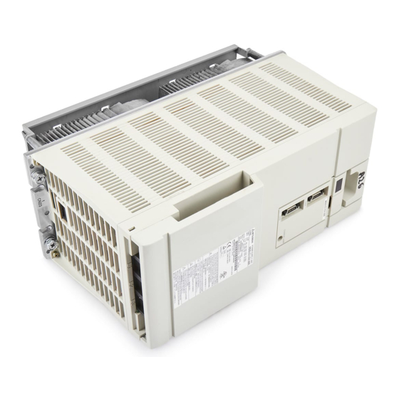
Mitsubishi MELDAS MDS-C1 Instruction Manual (330 pages)
AC SERVO/SPINDLE
Brand:
Mitsubishi
| Category:
Control Unit
| Size: 5.29 MB
Table of Contents
Table of Contents
10
Cautions for Mounting Load (Prevention of Impact on Shaft)
13
Installation of Spindle Motor
13
Tolerable Load of Axis
13
Installation of the Control Unit
13
Environmental Conditions
13
Panel Installation Hole Work Drawings (Panel Cut Drawings)
13
Installing the Spindle Detector
13
Noise Measures
13
Environmental Conditions
14
Installation of Servomotor
14
Installation Direction
15
Cautions for Mounting Load (Prevention of Impact on Shaft)
15
Tolerable Load of Axis
16
Oil and Waterproofing Measures
17
Cable Stress
19
Environmental Conditions
20
Tolerable Load of Axis
20
Installation of Spindle Motor
20
Installation of the Control Unit
21
Installation Direction and Clearance
22
Prevention of Entering of Foreign Matter
22
Panel Installation Hole Work Drawings (Panel Cut Drawings)
23
Each Unit's Heating Value
24
Heat Radiation Countermeasures
25
Installing the Magnetic Sensor
26
Installing the Spindle Detector
26
Installing the Encoder
28
Installing the Spindle End PLG
29
Noise Measures
32
Part System Connection Diagram
36
Main Circuit Terminal Block/Control Circuit Connector
37
Connectors
37
Names and Applications of Main Circuit Terminal Block Signals and Control Circuit
37
Connector Pin Assignment
38
NC and Drive Unit Connection
41
Motor and Detector Connection
42
Connecting the Full-Closed Loop System
49
Connecting the Synchronous Control System
52
Connection of the Spindle Motor
60
Connection of Power Supply
65
Standard Connection
65
Two-Part System Control of Power Supply Unit
66
Using Multiple Power Supply Units
67
Connecting the Grounding Cable
68
Connecting the Protective Grounding (PE) and Frame Ground (FG)
68
Grounding Cable Size
68
Wiring of Contactors
69
Contactor Power on Sequences
70
Contactor Shutoff Sequences
70
Contactor Control Signal (MC1) Output Circuit
71
Wiring of the Motor Brake
72
Motor Brake Release Sequence
72
Control During the Servo off Command
72
Operation Sequences When an Emergency Stop Occurs
72
Motor Brake Control Connector (CN20) Output Circuit
73
Dynamic Brake Unit Wiring
74
Spindle Coil Changeover
75
Coil Changeover Control
75
Wiring
76
Wiring of an External Emergency Stop
77
External Emergency Stop Setting
77
Operation Sequences of CN23 External Emergency Stop Function
78
Example of Emergency Stop Circuit
79
Setting the Rotary Switch
81
Initial Setup
81
Transition of LED Display after Power Is Turned on
82
Servo Standard Specifications and High-Gain Specifications
83
Setting the Initial Parameters for the Servo Drive Unit (High-Gain Specifications)
84
Setting the Standard Parameters
84
Limitations to Electronic Gear Setting Value
87
List of Standard Parameters for each Servomotor
88
Servo Parameter List
94
Setting the Initial Parameters for the Servo Drive Unit (Standard Specifications)
107
Setting the Standard Parameters
107
Limitations to Electronic Gear Setting Value
110
List of Standard Parameters for each Servomotor
111
Servo Parameter List
118
Setting the Initial Parameters for the Spindle Drive Unit
130
Spindle Specification Parameters
130
List of Spindle Parameters
135
Initial Adjustment of the Spindle PLG
164
Adjusting the PLG Installation
164
Z Phase Automatic Adjustment
169
Motor End PLG Automatic Adjustment
170
Spindle End PLG Automatic Adjustment
171
D/A Output Specifications for Servo Drive Unit
173
D/A Output Specifications
173
Output Data Settings
174
Setting the Output Magnification
174
Gain Adjustment
175
Current Loop Gain
175
Speed Loop Gain
175
Position Loop Gain
177
Position Loop Gain 1
179
Characteristics Improvement
180
Optimal Adjustment of Cycle Time
180
Vibration Suppression Measures
182
Improving the Cutting Surface Precision
185
Improvement of Characteristics During Acceleration/Deceleration
188
Improvement of Protrusion at Quadrant Changeover
191
Improvement of Overshooting
196
Adjustment During Full Closed Loop Control
200
Outline
200
Speed Loop Delay Compensation
201
Dual Feedback Control (Optional Function)
202
Settings for Emergency Stop
204
Deceleration Control
204
Vertical Axis Drop Prevention Control
206
Collision Detection
208
D/A Output Specifications for Spindle Drive Unit
212
D/A Output Specifications
212
Setting the Output Data
212
Setting the Output Magnification
213
Spindle Control Signal
214
Spindle Control Input (NC to SP)
214
Spindle Control Output
219
Adjustment Procedures for each Control
225
Basic Adjustments
225
Adjusting the Acceleration/Deceleration Operation
226
Adjusting the Orientation Control
229
Adjusting the Orientation Control
231
Adjusting the Synchronous Tap Control
236
Adjusting the C-Axis Control
240
Adjusting the Spindle Synchronous Control
242
Points of Caution and Confirmation
247
LED Display When Alarm or Warning Occurs
248
Troubleshooting at Power on
249
Protective Functions List of Units
250
List of Alarms
250
List of Warnings
255
Troubleshooting
256
Troubleshooting for each Alarm no
256
Troubleshooting for each Warning no
284
Parameter Numbers During Initial Parameter Error
288
Troubleshooting the Spindle System When There Is no Alarm or Warning
289
Inspections
293
Service Parts
293
Adding and Replacing Units and Parts
294
Replacing the Unit Fan
295
Appendix 1-1 Cable Connection Diagram
297
Appendix 1-2 Connector Outline Dimension Drawings
305
Appendix 2-1 Compliance to EC Directives
307
Appendix 2-1-1 European EC Directives
307
Appendix 2-2-2 Cautions for EC Directive Compliance
307
Appendix
309
Introduction
310
Appendix
310
EMC Instructions
310
Appendix 3-1 Introduction
310
Appendix 3-2 EMC Instructions
310
Appendix 3-3 EMC Measures
311
Appendix 3-4 Measures for Panel Structure
311
Appendix 3-4-1 Measures for Control Panel Unit
311
Appendix 3-4-2 Measures for Door
312
Appendix 3-4-3 Measures for Operation Board Panel
312
Appendix 3-4-4 Shielding of the Power Supply Input Section
312
Appendix 3-5 Measures for Various Cables
313
Appendix 3-5-1 Measures for Wiring in Panel
313
Appendix 3-5-2 Measures for Shield Treatment
313
Appendix 3-5-3 Servomotor Power Cable
314
Appendix 3-5-4 Servo/Spindle Motor Feedback Cable
314
Appendix 3-5-5 Spindle Motor Power Cable
315
Appendix 3-5-6 Cable between Control Panel and Operation Board Panel
315
Appendix
316
EMC Countermeasure Parts
316
Appendix 3-6-1 Shield Clamp Fitting
316
Appendix 3-6 EMC Countermeasure Parts
316
Appendix 3-6-2 Ferrite Core
317
Appendix 3-6-3 Power Line Filter
318
Appendix 3-6-4 Surge Protector
324
Appendix 4-1 Servo/Spindle Drive Unit Categories Based on Higher Harmonic Suppression Countermeasure Guidelines
326
Revision History
328
Advertisement
Advertisement
Related Products
Mitsubishi Melsec-LJ71E71-100
Mitsubishi MELSECNET 10
Mitsubishi MAC-588IF-E
Mitsubishi MELSEC-Q Q Series
Mitsubishi MELSEC QD75P1
Mitsubishi MELSEC QD75P2
Mitsubishi MELSEC QD75P4
Mitsubishi MELSEC QD75D1
Mitsubishi MELSEC QD75D2
Mitsubishi M80W Series
Mitsubishi Categories
Air Conditioner
Controller
Projector
Automobile
Engine
More Mitsubishi Manuals
Login
Sign In
OR
Sign in with Facebook
Sign in with Google
Upload manual
Upload from disk
Upload from URL