Sign In
Upload
Manuals
Brands
Fluke Manuals
Measuring Instruments
Endurance E1RH
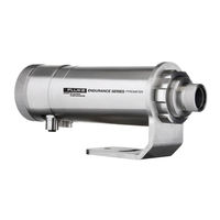
Fluke Endurance E1RH Manuals
Manuals and User Guides for Fluke Endurance E1RH. We have
3
Fluke Endurance E1RH manuals available for free PDF download: User Manual
Fluke Endurance E1RH User Manual (147 pages)
Innovative High Temperature Infrared Pyrometers
Brand:
Fluke
| Category:
Measuring Instruments
| Size: 6.53 MB
Table of Contents
Table of Contents
3
List of Tables
8
List of Figures
9
Compliance Statement
12
Safety Information
13
Contacts
16
1 Description
17
Table 1-1: Model Overview
17
2 Technical Data
18
Measurement Specification
18
Optical Specifications
21
Electrical Specifications
23
Environmental Specifications
24
Dimensions
25
Figure 2-1: Dimensions
25
Scope of Delivery
26
3 Basics
27
Measurement of Infrared Temperature
27
Emissivity for 1-Color Measurements
27
Theory for 2-Color Measurements
28
Low or Changing Emissivities
28
Partially Obscured Targets
28
Targets Smaller than Field of View
29
Slope
29
Attenuation
29
4 Environment
30
Ambient Temperature
30
Atmospheric Quality
30
Electrical Interference
30
Figure 4-1: One Earth Ground at the Sensor (Left) or at the Power Supply (Right)
30
5 Installation
31
Distance to Object
31
Sensor Placement in 1 Color Mode
31
Sensor Placement in 2 Color Mode
31
Figure 5-1: Sensor Placement in 1 Color Mode
31
Figure 5-2: Sensor Placement in 2 Color Mode
32
Positioning
31
Figure 5-3: Acceptable Sensor Viewing Angles
33
Viewing Angles
33
Aiming and Focusing
34
Figure 5-4: Sensor Eyepiece and Reticle
34
Electrical Installation
35
Power Supply
35
Ethernet Connector
35
Power over Ethernet (Poe)
35
12-Pin Connector
35
Figure 5-5: Ethernet Connector Socket and Pin Assignment
35
Figure 5-6: Sensor Connection to a PC Using Poe
35
Table 5-1: Pin Assignment for 12-Pin Connector
36
Figure 5-7: 12-Pin Connector Pin Layout (Pin Side)
36
Inputs
37
Trigger
37
Analog Input
37
Emissivity/Slope Setting
37
Table 5-2: Ratio between Analog Input Current and Emissivity (Example)
37
Figure 5-8: Wiring the Trigger Input
37
Figure 5-9: Wiring the Analog Input
37
Background Temperature Compensation
38
Figure 5-10: Principle of Background Temperature Compensation
38
Outputs
39
Relay
39
Setpoint
39
Deadband
39
Figure 5-11: Spike Voltage Limitation for the Alarm Relay
39
Figure 5-12: Deadband Around the Setpoint (Example)
40
Analog Output
41
Figure 5-13: Wiring the Analog Output
41
6 Operation
42
Control Panel
42
Figure 6-1: Control Panel
42
Control Buttons
43
Menu Display
43
Sighting Indicator
43
Status Indicator
43
Target Temperature Display
43
Menu Structure
44
Information Menu
45
Configuration Menu
47
Unit Setup Menu
49
Interface Menu
52
Analog Menu
54
Post Processing
55
Averaging
55
Peak Hold
55
Reset by Time
55
Figure 6-2: Averaging
55
Reset by Trigger
56
Figure 6-3: Peak Hold and Reset by Time
56
Figure 6-4: Peak Hold and Reset by Trigger
56
Signal Drop with Reset
57
Figure 6-5: Signal Drop: Perpendicular
57
Figure 6-6: Signal Drop: Linear
57
Advanced Peak Hold
58
Valley Hold
58
Figure 6-7: Signal Drop: Averaging
58
Figure 6-8: Advanced Peak Hold
58
Advanced Valley Hold
59
Figure 6-9: Valley Hold
59
7 Rs485
60
Specification
60
Installation
60
Figure 7-1: Network in Linear Topology (Daisy Chain)
60
Wiring
61
Computer Interfacing
61
Figure 7-2: RS485 Communication
61
Figure 7-3: Wiring the Sensor's RS485 Interface with USB/RS485 Converter
61
Multiple Sensors
62
Figure 7-4: Wiring Multiple Sensors Via RS485 Interface with USB/RS485 Converter
62
8 Ethernet
63
Addressing
63
Advanced Address Settings
63
Figure 8-1: Command Prompt Window
63
PC Network Adapter
64
ASCII Programming
65
Http Server
65
Figure 8-2: Web Page
65
Video Streaming
66
9 Profinet Io
67
Configuration
67
Parameters
67
Messages
68
Table 9-1: Pyrometer Parameters
68
Table 9-2: Messages
68
Input Data
69
Output Data
69
Diagnostics
69
Table 9-3: Input Data
69
Table 9-4: Output Data
69
Table 9-5: Parameter Types
69
Table 9-6: Error Codes
70
10 Ethernnet/Ip
71
Configuration
71
Parameters
71
Input Data
72
Table 10-1: Pyrometer Parameters
72
Table 10-2: Input Data
72
Output Data
73
Diagnostics
73
Table 10-3: Output Data
73
Table 10-4: Parameter Types
73
Table 10-5: Error Codes
74
11 Options
75
Figure 11-1: Laser Indication
76
Laser Sighting (-L)
76
Figure 11-2: LED Spot Size Indication
77
LED Sighting (-D)
77
Video Sighting (-V)
77
Air/Water-Cooled Housing
78
Figure 11-3: Air/Water-Cooled Housing
78
Avoidance of Condensation
79
Table 11-1: Minimum Device Temperatures [°C/°F]
80
Manufacturer's Calibration Certificate
81
12 Accessories
82
Electrical Accessories
82
High Temp 12-Wire Cable (E-2Ccbxx)
83
Table 12-1: Cable Specification
83
Table 12-2: Color Assignment to DIN Connector
83
Figure 12-1: 12-Wire Cable, High Temp Version
83
Low Temp 12-Wire Cable (E-2Cltcbxx)
85
Table 12-3: Cable Specification
85
Table 12-4: Color Assignment to DIN Connector
85
Figure 12-2: 12-Wire Cable, Low Temp Version
85
Ethernet Poe Cable (E-Ethxtcbxx)
87
Table 12-5: Available Ethernet Poe Cables
87
Figure 12-3: Ethernet Poe Cable
87
Figure 12-4: Pin Assignment (Front View)
87
Terminal Block (E-TB)
88
Figure 12-5: Terminal Block with Wire Color Assignment
88
Terminal Block with Enclosure (E-TBN4)
89
Figure 12-6: Terminal Block with Enclosure
89
Power Supply DIN Rail (E-SYSPS)
90
Figure 12-7: Industrial Power Supply
90
Power Supply with Terminal Box (E-PS)
91
Figure 12-8: Power Supply with Terminal Box
91
USB/RS485 Converter (E-USB485)
93
Figure 12-9: USB/RS485 Converter
93
Poe Injector (E-POE)
94
Figure 12-10: Poe Injector
94
12-Pin Plug (E-2CCON)
95
Modline 5 Patch Cable (E-M5PK)
95
Figure 12-11: 12-Pin Plug
95
Figure 12-12: Modline 5 Patch Cable
95
Mechanical Accessories
96
Figure 12-13: Overview to Mechanical Accessories
96
Figure 12-14: Mounting Nut
97
Mounting Nut (E-MN)
97
Figure 12-15: Fixed Bracket
98
Fixed Bracket (E-FB)
98
Adjustable Bracket (E-AB)
99
Figure 12-16: Adjustable Bracket
99
Figure 12-17: Swivel Bracket
100
Swivel Bracket (E-SB)
100
Figure 12-18: Installation of the Sighting Tube
101
Figure 12-19: Dimensions for the Sighting Tube
101
Sighting Tube (A-ST-XX)
101
Figure 12-20: Available Sighting Tubes
102
Figure 12-21: Pipe Adapter
103
Pipe Adapter (E-PA)
103
Figure 12-22: Protective Front Window
104
Protective Front Window (E-PW)
104
Figure 12-23: Right-Angle Mirror
105
Right-Angle Mirror (E-RA)
105
Air Purge (E-AP)
106
Figure 12-24: Air Purge
106
Figure 12-25: Thread Adapter
107
Thread Adapter (E-MFA-7)
107
Figure 12-26: Mounting Flange
108
Mounting Flange (E-MF-7)
108
Figure 12-27: Polarizing Filter
109
Polarizing Filter (E-PFEC)
109
End Cap (E-ECAP)
110
Figure 12-28: End Cap
110
Figure 12-29: Modline 5 Adapter Kit
111
Modline 5 Adapter Kit (E-M5WJAK)
111
Figure 12-30: Modline 5 Universal Adapter
112
Modline 5 Universal Adapter (E-UAA)
112
Figure 12-31: Modline 5 Water Jacket Adapter Kit
114
Modline 5 Water Jacket Adapter Kit (E-AK-7)
114
13 Maintenance
115
Troubleshooting Minor Problems
115
Fail-Safe Operation
115
Table 13-1: Troubleshooting
115
Table 13-2: Fail-Safe Error Codes
116
Table 13-3: Error Codes for Analog Output
116
Window Cleaning
118
Window Exchange
119
14 Ascii Programming
120
Remote Versus Manual Settings
120
Command Structure
120
Timing
120
Requesting a Parameter (Poll Mode)
120
Setting a Parameter (Poll Mode)
120
Sensor Response
121
Sensor Notification
121
Error Messages
121
Transfer Modes
121
Sensor Information
121
Sensor Setup
122
General Settings
122
Emissivity Setting
122
Background Temperature Compensation
122
Multiplex Mode for the Analog Input
122
Table 14-1: Sensor Information
122
Temperature Hold Functions
123
Sensor Control
123
Analog Output
123
Relay Output
123
RS485 Communication
123
Multidrop Mode
123
Command List
125
15 Appendix
130
Optical Diagrams
130
E1ML Models
130
Figure 15-1: Optical Diagrams E1ML-F0 Models
130
Figure 15-2: Optical Diagrams E1ML-F1 Models
130
Figure 15-3: Optical Diagrams E1ML-F2 Models
130
E1MH Models
131
Figure 15-4: Optical Diagrams E1MH-F0 Models
131
Figure 15-5: Optical Diagrams E1MH-F1 Models
131
Figure 15-6: Optical Diagrams E1MH-F2 Models
131
E2ML Models
132
Figure 15-7: Optical Diagrams E2ML-F0 Models
132
Figure 15-8: Optical Diagrams E2ML-F1 Models
132
Figure 15-9: Optical Diagrams E2ML-F2 Models
132
E2MM Models
133
Figure 15-10: Optical Diagrams E2MM-F0 Models
133
Figure 15-11: Optical Diagrams E2MM-F1 Models
133
Figure 15-12: Optical Diagrams E2MM-F2 Models
133
E2MH Models
134
Figure 15-13: Optical Diagrams E2MH-F0 Models
134
Figure 15-14: Optical Diagrams E2MH-F1 Models
134
Figure 15-15: Optical Diagrams E2MH-F2 Models
134
E3ML Models
135
Figure 15-16: Optical Diagrams E3ML-F0 Models
135
Figure 15-17: Optical Diagrams E3ML-F1 Models
135
Figure 15-18: Optical Diagrams E3ML-F2 Models
135
E3MH Models
136
Figure 15-19: Optical Diagrams E3MH-F0 Models
136
Figure 15-20: Optical Diagrams E3MH-F1 Models
136
Figure 15-21: Optical Diagrams E3MH-F2 Models
136
E1RL Models
137
Figure 15-22: Optical Diagrams E1RL-F0 Models
137
Figure 15-23: Optical Diagrams E1RL-F1 Models
137
Figure 15-24: Optical Diagrams E1RL-F2 Models
137
E1RH Models
138
Figure 15-25: Optical Diagrams E1RH-F0 Models
138
Figure 15-26: Optical Diagrams E1RH-F1 Models
138
Figure 15-27: Optical Diagrams E1RH-F2 Models
138
E2RL Models
139
Figure 15-28: Optical Diagrams E2RL-F0 Models
139
Figure 15-29: Optical Diagrams E2RL-F1 Models
139
Figure 15-30: Optical Diagrams E2RL-F2 Models
139
Spot Size Calculator
140
Figure 15-31: Spot Size Calculator
140
Determination of Emissivity
141
Typical Emissivity Values
141
Determination of Slope
145
Signal Reduction
146
Figure 15-32: Model E1RH - Allowed Signal Reduction over Target Temperature
146
Figure 15-33: Model E1RL - Allowed Signal Reduction over Target Temperature
146
Figure 15-34: Model E2RL - Allowed Signal Reduction over Target Temperature
147
Advertisement
Fluke Endurance E1RH User Manual (104 pages)
Innovative High Temperature Infrared Pyrometers
Brand:
Fluke
| Category:
Measuring Instruments
| Size: 4.62 MB
Table of Contents
Table of Contents
5
List of Figures
11
1 Safety Instructions
13
Table 1: General Symbols
14
2 Product Description
15
Figure 1: Endurance® Model Identification Matrix
16
Theory of Operation for 2-Color Sensors
17
Partially Obscured Targets
17
Targets Smaller than Field of View
17
Emissivity and 1-Color (Single Wavelength) Measurements
17
Slope (2-Color Ratio) Measurements
18
3 Technical Data
19
General Specifications
19
Electrical Specifications
20
Measurement Specifications
21
Optical Specifications
22
Dimensions
23
Figure 2: Spot Size Chart
23
Figure 3: Dimensions of Endurance® Sensor
23
Figure 4: Dimensions of Endurance® Sensor in Air/Water-Cooled Housing Option
23
Scope of Delivery
24
4 Environment
24
Ambient Temperature
24
Atmospheric Quality
24
Electrical Interference
25
5 Installation
25
Mechanical Installation
25
Distance to Object
25
Sensor Placement (1-Color Mode)
25
Figure 5: Proper Sensor Placement in 1-Color Mode
25
Sensor Placement (2-Color Mode)
26
Figure 6: Sensor Placement in 2-Color Mode
26
Viewing Angles
27
Figure 7: Acceptable Sensor Viewing Angles
27
Aiming and Focusing
28
Figure 8: Sensor Eyepiece and Reticle
28
Electrical Installation
29
M16 12-Pin DIN Connector Signal Assignment
29
Figure 9: M16 12-Pin Connector (Left) and the Corresponding Cable Socket (Right)
29
Figure 10: M16 DIN Connector Signal Assignment
29
M12 4-Socket Lan/Ethernet Connector
30
Accessory Cables and Terminal Block
30
Figure 11: M12 Socket (Left) and the Corresponding Cable Plug (Right)
30
Figure 12: Ethernet Cable with M12 Plug and RJ45 Connector
30
Figure 13: M16 12-Conductor Shielded Cable with Colored Wire/Signal Assignments
31
Figure 14: M12 4-Conductor Shielded Cable with RJ45 on Counter Side
31
Power Supply
32
Computer Interfacing Via RS485 Link
32
Figure 15: Endurance® Series Labeled Terminal Block
32
Addressing the Endurance® Sensor in a RS485 Multidrop Network
33
Figure 16: USB/RS485 Converter
33
6 Device Control
34
Control Panel
34
The Object / Target Temperature Display (Green 7-Segment LED Type)
34
Figure 17: Control Panel
34
Figure 18: Upper Object/Target Temperature Display
34
The Screen / Menu Display
35
The LASER / LED / CAMERA Indicator LED (Red)
35
The Status Indicator LED (Green)
35
The 4 Control Panel Pushbuttons
35
Figure 19: Lower Screen / Menu Display
35
Figure 20: Upper LASER / LED /CAMERA Activation LED (Red)
35
Figure 21: Lower Status Indicator LED (Green)
35
The Control Panel Menu Structure and Their Associated Entries
36
Figure 22: Overview about the Menu Structure with Five (5) Sub-Menus
37
Figure 23: the INFORMATION MENU with Sensor Type Related Variations
38
The INFORMATION MENU
38
Figure 24: the CONFIGURATION MENU with Sensor Type Related Variations
40
The CONFIGURATION MENU
40
Figure 25: the UNIT SETUP MENU with Sensor Type Related Variations
42
The UNIT SETUP MENU
42
Figure 26: the Static (Fixed) INTERFACE MENU
45
The INTERFACE MENU
45
Figure 27: the Static (Fixed) ANALOG MENU
47
The ANALOG MENU
47
7 Signal Processing
48
Averaging
48
Peak Hold
48
Reset Peak Hold by Peak Hold Time Expiration
48
Figure 28: Averaging
48
Reset Peak Hold by External Trigger Signal
49
Figure 29: Peak Hold Reset by Peak Hold Time Expiration
49
Figure 30: Peak Hold Reset by External Trigger Signal
49
Signal Slope (Decay) in Case of Peak Hold Reset
50
Figure 31: Perpendicular Signal Drop (Default Mode)
50
Figure 32: Linear Signal Drop (Decay Mode)
50
Advanced Peak Hold
51
Valley Hold
51
Figure 33: Average Time Dependent Signal Drop (Averaging Mode)
51
Figure 34: Advanced Peak Hold
51
Advanced Valley Hold
52
Setpoint
52
Deadband
52
Figure 35: Valley Hold
52
Outputs
53
Analog Output (Current Loop)
53
Relay Outputs
53
Trigger
53
Figure 36: Deadband Example
53
Factory Defaults
54
Table 2: Factory Defaults
54
8 Device Options
55
Adjustable Focus (3 Focus Options Available)
55
Laser Sighting (Sighting Option L)
55
Figure 37: LASER Spot Size Indication
55
LED Sighting (Sighting Option D)
56
Video Sighting (Sighting Option V)
56
Air/Water Cooled Housing (Cooling Option 1)
56
Figure 38: LED Spot Size Indication
56
Avoidance of Condensation
57
Figure 39: Endurance® Head with Air/Water-Cooled Housing Option
57
PROFINET IO (Communication Option 1)
58
Description
58
Table 3: Minimum Device Temperatures [°C/°F]
58
I/O Device Configuration
59
Parameter Setting
59
Structure of the Input/Output Data
60
Diagnostics
61
ISO Calibration Certificate, Based on Dakks (German Accreditation Body)
62
9 Accessories
63
Electrical Accessories
63
Table 4: Electrical Accessories
63
High Temp. Multi-Conductor Cable with M16 Connector (E-2Ccbxx)
64
Figure 40: High Temp. Multi-Conductor Cable with M16 Connector (E-2Ccbxx)
65
Low Temp. Multi-Conductor Cable with M16 Connector (E-2Cltcbxx)
65
Figure 41: Low Temp. Multi-Conductor Cable with M16 Connector (E-2Cltcbxx)
66
High Temp. Ethernet Cable with M12 Connector (E-Ethcbxx)
66
Endurance® Terminal Block Accessory (E-TB)
67
Figure 42: High Temp. Ethernet Cable with M12, RJ45 Connector (E-Ethcbxx)
67
Figure 43: Low Temp. Ethernet Cable with M12, RJ45 Connector (E-Ethltcbxx)
67
Low Temp. Ethernet Cable with M12 Connector (E-Ethltcbxx)
67
24VDC, 1.2A Industrial Power Supply, DIN Rail Mount (E-SYSPS)
68
Endurance® Terminal Block in a NEMA 4 Enclosure (E-TBN4)
68
Figure 44: Endurance® Terminal Block (E-TB) with Wire Color Assignment
68
Figure 45: Endurance® Terminal Block in a NEMA 4 Enclosure (E-TBN4)
68
24VDC, 1.1A, 100-240VAC Power Supply in NEMA 4/IP65 Case (E-PS)
69
Figure 46: 24VDC, 1.2A Industrial Power Supply (E-SYSPS)
69
Figure 47: 24VDC, 1.1A, 100-240VAC Power Supply in NEMA 4/IP65 Case (E-PS)
70
Poe Injector to Provide Power over a Single Ethernet Hub (E-POE)
70
12-Socket DIN Cable Connector (E-2CCON) for Multi-Conductor Cable
71
Figure 48: Poe Injector to Provides Power over a Single Ethernet Hub (E-POE)
71
Figure 49: 12-Socket DIN Cable Connector (E-2CCON) for Multi-Conductor Cable
71
Figure 50: Modline5 Patch Cable Kit to Use Existing Modline5 Cables (E-M5PK)
72
Figure 51: USB to RS232/422/485 Converter (E-USB485)
72
Modline5 Patch Cable Kit to Use Existing Modline5 Cables (E-M5PK)
72
USB to RS232/422/485 Converter (E-USB485)
72
Mechanical/Optical Accessories for Endurance® Sensors Only
73
Figure 52: Extraction View of Endurance® Sensor with Mechanical Accessories
73
Table 5: Accessories for Endurance® Sensors Only
73
Air Purge Collar (E-AP)
74
Figure 53: Air Purge Collar (E-AP)
74
Figure 54: Pipe Adapter to Attach Sighting Tubes (E-PA)
74
Pipe Adapter to Attach Sighting Tubes (E-PA)
74
Adjustable Bracket (E-AB)
75
Figure 55: Mounting Nut (E-MN)
75
Figure 56: Drawing and Photo of Fixed Bracket (E-FB)
75
Fixed Bracket (E-FB)
75
Mounting Nut (E-MN)
75
Figure 57: Adjustable Bracket (E-AB)
76
Figure 58: Swivel Bracket (E-SB)
76
Swivel Bracket (E-SB)
76
Adapter Kit to Use Endurance® Sensors in Modline5 WJA (E-M5WJAK)
77
Figure 59: Right Angle Mirror for Targets at Right Angles to Sensor Axis (E-RA)
77
Figure 60: Adapter Kit to Use Endurance® Sensors in Modline5 WJA (E-M5WJAK)
77
Right Angle Mirror for Targets at Right Angles to Sensor Axis (E-RA)
77
Adapter Kit for Endurance® in WJ-5 Water Jacket Installations (E-AK-7)
78
Endurance® Universal Adapter Accessory (E-UAA)
78
Figure 61: Endurance® Universal Adapter Accessory (E-UAA)
78
Figure 62: Adapter Kit for Endurance® in WJ-5 Water Jacket Installations (E-AK-7)
78
Mounting Flange (E-MF-7)
78
Figure 63: Mounting Flange (E-MF-7)
79
Figure 64: Flange Adapter to Allow Endurance® to Mount to MF-7 (E-MFA-7)
79
Figure 65: Replacement Glass End-Cap for Endurance® Sensors (E-ECAP)
79
Flange Adapter (E-MFA-7) to Allow Endurance® to Mount to E-MF-7
79
Replacement Glass End-Cap for Endurance® Sensors (E-ECAP)
79
Figure 66: Protective Front Window, Including O-Ring (E-PW)
80
Figure 67: Polarizing Filter End Cap for Use in High Temperature Applic. (E-PFEC)
80
Polarizing Filter End Cap for Use in High Temperature Applic. (E-PFEC)
80
Protective Front Window, Including O-Ring (E-PW)
80
Thermojacket and Related Accessories
81
Imperial Unit Thermojacket Housing for Endurance® Sensors (E-TJ1)
81
Table 6: Thermojacket and Related Accessories
81
Table 7: Approximate Required Coolant Flow Versus Outside Ambient Temperature
82
Figure 68: Dimensions for the Thermojacket
82
Metric Unit Thermojacket Housing for Endurance® Sensors (E-TJ1M)
83
Mounting Flange for Thermojacket (E-MF)
83
Adjustable Mounting Base for Thermojacket (E-MB)
83
Figure 69: Mounting Flange for Thermojacket (E-MF)
83
Figure 70: Adjustable Mounting Base for Thermojacket (E-MB)
83
Blast Gate Assembly with Quartz Window, HT Model (E-GTQ)
84
Figure 71: Explosion View of the Adjustable Mounting Base (E-MB)
84
Adjustable Pipe Adapter Assembly (E-APA)
85
Figure 72: Dimensions of the Blast Gate Assembly
85
Figure 73: Mounting the Blast Gate Assembly
85
Mounting Flange for Use with Sighting Tubes (E-MST)
86
30Cm (12") Sighting Tube, Ceramic up to 1500°C/2730°F (E-STC12)
86
Figure 74: Adjustable Pipe Adapter (E-APA)
86
Figure 75: Mounting Flange for Sighting Tube (E-MST)
86
30Cm (12") Sighting Tube, Stainless Steel up to 800°C/1470°F (E-ST12)
87
Figure 76: Ceramic Sighting Tube (E-STC12)
87
Figure 77: Stainlless Steel Sighting Tube (E-ST12)
87
30Cm (12") Sighting Tube, Carbon Steel, 45° End Cut (E-BEESIGHT)
88
Extraction Tool to Remove Endurance® from Thermojacket (E-TJET)
88
Figure 78: Carbon Steel Sighting Tube with 45° End Cut (E-BEESIGHT)
88
Figure 79: Drawing and Picture of the Extraction Tool (E-TJET)
88
Flow Regulator Accessories
89
Water Flow Regulator for Water Cooling (E-WR)
89
Table 8: Flow Regulators for Use with Cooling/Purging Options
89
Figure 80: Extraction Tool (E-TJET) Attached to Endurance® M16 Connector
89
Air Purging Flow Regulator Assembly with Air Filter (E-AR)
90
Figure 81: Water Flow Regulator (E-WR)
90
Figure 82: Air Purging Flow Regulator with Air Filter (E-AR)
90
Cooling Air Flow Regulator, High Capacity (E-CAFR)
91
Figure 83: Dimensions of Cooling Air Flow Regulator
91
10 Programming Guide
92
Remote Versus Manual Considerations
92
Command Structure
92
Transfer Modes
93
Poll Mode
93
Burst Mode
93
Command List
94
Table 9: Command List
94
Table 10: Assignment of Error-Codes
96
Command Examples
97
11 Maintenance
97
Table 11: Command Examples
97
Troubleshooting Minor Problems
98
Fail-Safe Operation
98
Fail-Safe Error Codes (Displayed or Transmitted Via Electrical Interface)
98
Table 12: Troubleshooting
98
Analog Output Current Values in Dependence of Fail-Safe Error Codes
99
Table 13: Fail-Safe Error Codes
99
Table 14: Current Output Values in Accordance to an Error
99
Cleaning the Lens
100
Changing the Window
101
12 Addendum
102
Determination of Slope (for 2 - Color Operation)
102
Percentage of Allowed Signal Reduction
102
Figure 84: Model L Percentage of Allowed Signal Reduction
102
Determination of Emissivity (for 1-Color Operation)
103
Typical Emissivity Values
103
Figure 85: Model H Percentage of Allowed Signal Reduction
103
Table 15: Typical Emissivity Values (Metals)
104
Table 16: Typical Emissivity Values (Non-Metals)
104
Fluke Endurance E1RH User Manual (106 pages)
Innovative High Temperature Infrared Pyrometers
Brand:
Fluke
| Category:
Measuring Instruments
| Size: 5.79 MB
Table of Contents
Table of Contents
4
1 Safety Instructions
10
Table 1: General Symbols
11
2 Description
12
Table 2: Integrated Sensor Head Models and Their Assigned Sensor Spectral Range
12
Figure 1: Identification Matrix for Endurance with Integrated Sensor Head
13
Theory of Operation for Ratio (2-Color) Sensors
14
Partially Obscured Targets
14
Targets Smaller than Field of View
14
Emissivity and 1-Color (Single Wavelength) Measurements
14
Slope (2-Color Ratio) Measurements
15
3 Technical Data
16
General Specifications
16
Electrical Specifications
17
Measurement Specifications
20
Optical Specifications
21
Measurement Spot Size Regarding the Selected Focus and Model Options
22
Figure 2: Spot Size Calculation Regarding the Distance to the Integrated Sensor Head
22
Dimensions
23
Figure 3: Dimensions of the Endurance Sensor Without Air/Water Cooled Housing
23
Scope of Delivery
24
4 Sensor Location
24
Ambient Temperature
24
Atmospheric Quality
24
Electrical Interference
25
Distance to Object
25
Sensor Placement (1-Color Mode)
25
Figure 4: Proper Sensor Placement in 1-Color Mode
25
Sensor Placement (2-Color Mode)
26
Figure 5: Sensor Placement in 2-Color Mode
26
Viewing Angles
27
5 Installation
27
Mounting the Sensor
27
Aiming and Focusing
27
Figure 6: Acceptable Sensor Viewing Angles
27
Figure 7: Sensor Eyepiece and Reticle
28
Electrical Installation
29
M16 12-Pin DIN Connector Signal Assignment
29
M12 4-Socket Lan/Ethernet Connector
29
Figure 8: M16 12-Pin Connector (Upper), the Corresponding Cable Socket (Lower), the Cable Wire Coding Table (Right)
29
Accessory Cables and Terminal Block
30
Figure 9: M12 Socket (Left) and the Corresponding Cable Plug (Right)
30
Figure 10: Ethernet Cable with M12 Plug and RJ45 Connector
30
Figure 11: M16 12-Conductor Shielded Cable with Colored Wire/Signal Assignments
31
Figure 12: M12 4-Conductor Shielded Cable with RJ45 on Counter Side
31
Power Supply
32
Computer Interfacing Via RS485 Link
32
Figure 13: Endurance Series Labeled Terminal Block
32
Addressing the Endurance Sensor in a RS485 Multidrop Network
33
Figure 14: USB/RS485 Converter
33
6 Device Control
34
Control Panel
34
The Object / Target Temperature Display (Green 7-Segment LED Type)
34
Figure 15: Control Panel
34
Figure 16: Upper Object/Target Temperature Display
34
The Screen / Menu Display
35
The LASER / LED / CAMERA Indicator LED (Red)
35
The Status Indicator LED (Green)
35
The 4 Control Panel Pushbuttons
35
Figure 17: Lower Screen / Menu Display
35
Figure 18: Upper LASER / LED /CAMERA Activation LED (Red)
35
Figure 19: Lower Status Indicator LED (Green)
35
The Control Panel Menu Structure and Their Associated Entries
36
Figure 20: Overview about the Menu Structure with Five (5) Sub-Menus
37
Figure 21: the INFORMATION MENU with Sensor Type Related Variations
38
The INFORMATION MENU
38
Figure 22: the CONFIGURATION MENU with Sensor Type Related Variations
40
The CONFIGURATION MENU
40
Figure 23: the UNIT SETUP MENU with Sensor Type Related Variations
42
The UNIT SETUP MENU
42
Figure 24: the Static (Fixed) INTERFACE MENU
45
The INTERFACE MENU
45
Figure 25: the Static (Fixed) ANALOG MENU
47
The ANALOG MENU
47
7 Signal Processing
48
Averaging
48
Peak Hold
48
Reset Peak Hold by Peak Hold Time Expiration
48
Figure 26: Averaging
48
Reset Peak Hold by External Trigger Signal
49
Figure 27: Peak Hold Reset by Peak Hold Time Expiration
49
Figure 28: Peak Hold Reset by External Trigger Signal
49
Signal Slope (Decay) in Case of Peak Hold Reset
50
Figure 29: Perpendicular Signal Drop (Default Mode)
50
Figure 30: Linear Signal Drop (Decay Mode)
50
Advanced Peak Hold
51
Valley Hold
51
Figure 31: Average Time Dependent Signal Drop (Averaging Mode)
51
Figure 32: Advanced Peak Hold
51
Advanced Valley Hold
52
Setpoint
52
Deadband
52
Figure 33: Valley Hold
52
Outputs
53
Analog Output (Current Loop)
53
Relay Outputs
53
Trigger
53
Figure 34: Deadband Example
53
Factory Defaults
54
Table 3: Factory Defaults
54
8 Options
55
Adjustable Focus
55
Laser Sighting (Sighting Option L)
55
Figure 35: LASER Spot Size Indication
55
LED Sighting (Sighting Option D)
56
Figure 36: LED Spot Size Indication
56
Video Camera Sighting (Sighting Option V)
57
Air/Water Cooled Housing (Cooling Option 1)
58
Avoidance of Condensation
58
Figure 37: Endurance Head with Air/Water-Cooled Housing
58
Table 4: Minimum Device Temperatures [°C/°F]
59
ISO Calibration Certificate
60
PROFINET IO (Communication Option 1)
61
Description
61
I/O Device Configuration
61
Parameter Setting
62
Structure of the Input/Output Data
62
Diagnostics
63
Ethernet/Ip (Communication Option 2)
65
Description
65
Configuration
65
Figure 38: Adding Modules Using Controller Organizer
66
Figure 39: Selecting Endurance EDS from the Library
66
Figure 40: Device Settings (EDS)
67
Figure 41: Selecting Generic Ethernet Module from the Library
67
Parameter Setting
68
Figure 42: Device Settings Via Manual Configuration
68
Figure 43: Endurance Configuration Data as Seen in Controller Tags (Rockwell Studio5000 Software)
69
Figure 44: Controller Tags: Parameter Number and Value and Their Destination Registers in the Device
70
Figure 45: Sample Instruction for Sending Output Data
70
Figure 46: Input Data Conversion
70
9 Accessories
72
Electrical Accessories
72
Table 5: Electrical Accessories
72
Figure 47: High Temp. Multi-Conductor Cable with M16 Connector (E-2Ccbxx)
73
High Temp. Multi-Conductor Cable (E-2Ccbxx)
73
Low Temp. Multi-Conductor Cable (E-2Cltcbxx)
74
Figure 49: High Temp. Ethernet Cable with M12, RJ45 Connector (E-Ethcbxx)
75
Figure 50: Low Temp. Ethernet Cable with M12, RJ45 Connector (E-Ethltcbxx)
75
High Temp. Ethernet Cable (E-Ethcbxx)
75
Low Temp. Ethernet Cable (E-Ethltcbxx)
75
Figure 51: Terminal Block (E-TB) with Wire Color Assignment
76
Terminal Block Accessory (E-TB)
76
Figure 52: Terminal Block in a NEMA 4 Enclosure (E-TBN4)
77
Figure 53: Dimensions of Enclosure
77
Terminal Block in a NEMA 4 Enclosure (E-TBN4)
77
Figure 54: 24VDC, 1.3 a Industrial Power Supply (E-SYSPS)
78
Industrial Power Supply, DIN Rail Mount (E-SYSPS)
78
24VDC, 1.1A, 100-240VAC Power Supply in NEMA 4/IP65 Case (E-PS)
79
Figure 55: 24VDC, 1.1A, 100-240VAC Power Supply in NEMA 4/IP65 Case (E-PS)
79
Figure 56: Poe Injector to Provides Power over a Single Ethernet Hub (E-POE)
80
Poe Injector to Provide Power over a Single Ethernet Hub (E-POE)
80
12-Socket DIN Cable Connector (E-2CCON) for Multi-Conductor Cable
81
Figure 57: 12-Socket DIN Cable Connector (E-2CCON) for Multi-Conductor Cable
81
Figure 58: Modline5 Patch Cable Kit to Use Existing Modline5 Cables (E-M5PK)
81
Modline5 Patch Cable Kit to Use Existing Modline5 Cables (E-M5PK)
81
Figure 59: USB to RS232/422/485 Converter (E-USB485)
82
USB to RS232/422/485 Converter (E-USB485)
82
Mechanical Accessories
83
Figure 60: Endurance Sensor with Accessories
83
Table 6: Accessories
83
Air Purge Collar (E-AP)
84
Figure 61: Air Purge Collar (E-AP)
84
Figure 62: Pipe Adapter to Attach Sighting Tubes (E-PA)
84
Pipe Adapter to Attach Sighting Tubes (E-PA)
84
Figure 63: Mounting Nut (E-MN)
85
Figure 64: Drawing and Photo of Fixed Bracket (E-FB)
85
Fixed Bracket (E-FB)
85
Mounting Nut (E-MN)
85
Adjustable Bracket (E-AB)
86
Figure 65: Adjustable Bracket (E-AB)
86
Figure 66: Swivel Bracket (E-SB)
86
Swivel Bracket (E-SB)
86
Adapter Kit to Use Endurance Sensors in Modline5 WJA (E-M5WJAK)
87
Figure 67: Right Angle Mirror for Targets at Right Angles to Sensor Axis (E-RA)
87
Figure 68: Adapter Kit to Use Endurance Sensors in Modline5 WJA (E-M5WJAK)
87
Right Angle Mirror for Targets at Right Angles to Sensor Axis (E-RA)
87
Adapter Kit for Endurance in WJ-5 Water Jacket Installations (E-AK-7)
88
Endurance Universal Adapter Accessory (E-UAA)
88
Figure 69: Endurance Universal Adapter Accessory (E-UAA)
88
Figure 70: Adapter Kit for Endurance in WJ-5 Water Jacket Installations (E-AK-7)
88
Figure 71: Mounting Flange (E-MF-7)
89
Figure 72: Flange Adapter to Allow Endurance to Mount to MF-7 (E-MFA-7)
89
Flange Adapter (E-MFA-7) to Allow Endurance to Mount to E-MF-7
89
Mounting Flange (E-MF-7)
89
Figure 73: Replacement Glass End-Cap for Endurance Sensors (E-ECAP)
90
Figure 74: Protective Front Window, Including O-Ring (E-PW)
90
Protective Front Window, Including O-Ring (E-PW)
90
Replacement Glass End-Cap for Endurance Sensors (E-ECAP)
90
Figure 75: Polarizing Filter End Cap for Use in High Temperature Applic. (E-PFEC)
91
Polarizing Filter End Cap for Use in High Temperature Applic. (E-PFEC)
91
10 Programming Guide
92
Remote Versus Manual Considerations
92
Command Structure
92
Transfer Modes
93
Poll Mode
93
Burst Mode
93
Command List
94
Table 7: Command List
94
Table 8: Assignment of Error-Codes
96
Command Examples
97
Table 9: Command Examples
97
11 Maintenance
98
Troubleshooting Minor Problems
98
Fail-Safe Operation
98
Table 10: Troubleshooting
98
Analog Output Current Values in Dependence of Fail-Safe Error Codes
99
Fail-Safe Error Codes (Displayed or Transmitted Via Electrical Interface)
99
Table 11: Fail-Safe Error Codes
99
Table 12: Current Output Values in Accordance to an Error
99
Cleaning the Lens
101
Changing the Window
101
12 Addendum
102
Determination of Emissivity
102
Typical Emissivity Values
102
Table 13: Typical Emissivity Values (Metals)
102
Determination of Slope
103
Table 14: Typical Emissivity Values (Non-Metals)
103
Attenuation
104
Figure 76: Model E1RL Percentage of Allowed Signal Reduction
105
Figure 77: Model E1RH Percentage of Allowed Signal Reduction
105
Figure 78: Model E2RL Percentage of Allowed Signal Reduction
106
Advertisement
Advertisement
Related Products
Fluke Endurance E1ML
Fluke Endurance E1MH
Fluke Endurance E1RL
Fluke E1M
Fluke E1R
Fluke endurance series
Fluke etherscope II
Fluke ESA614
Fluke Endurance E2ML
Fluke Endurance E2MM
Fluke Categories
Measuring Instruments
Test Equipment
Multimeter
Thermometer
Laboratory Equipment
More Fluke Manuals
Login
Sign In
OR
Sign in with Facebook
Sign in with Google
Upload manual
Upload from disk
Upload from URL