Sign In
Upload
Manuals
Brands
Fluke Manuals
Measuring Instruments
E1M
Fluke E1M Manuals
Manuals and User Guides for Fluke E1M. We have
1
Fluke E1M manual available for free PDF download: User Manual
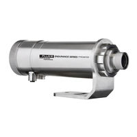
Fluke E1M User Manual (147 pages)
Innovative High Temperature Infrared Pyrometers
Brand:
Fluke
| Category:
Measuring Instruments
| Size: 6.53 MB
Table of Contents
Table of Contents
3
List of Tables
8
List of Figures
9
Compliance Statement
12
Safety Information
13
Contacts
16
1 Description
17
Table 1-1: Model Overview
17
2 Technical Data
18
Measurement Specification
18
Optical Specifications
21
Electrical Specifications
23
Environmental Specifications
24
Dimensions
25
Figure 2-1: Dimensions
25
Scope of Delivery
26
3 Basics
27
Measurement of Infrared Temperature
27
Emissivity for 1-Color Measurements
27
Theory for 2-Color Measurements
28
Low or Changing Emissivities
28
Partially Obscured Targets
28
Targets Smaller than Field of View
29
Slope
29
Attenuation
29
4 Environment
30
Ambient Temperature
30
Atmospheric Quality
30
Electrical Interference
30
Figure 4-1: One Earth Ground at the Sensor (Left) or at the Power Supply (Right)
30
5 Installation
31
Distance to Object
31
Sensor Placement in 1 Color Mode
31
Sensor Placement in 2 Color Mode
31
Figure 5-1: Sensor Placement in 1 Color Mode
31
Figure 5-2: Sensor Placement in 2 Color Mode
32
Positioning
31
Figure 5-3: Acceptable Sensor Viewing Angles
33
Viewing Angles
33
Aiming and Focusing
34
Figure 5-4: Sensor Eyepiece and Reticle
34
Electrical Installation
35
Power Supply
35
Ethernet Connector
35
Power over Ethernet (Poe)
35
12-Pin Connector
35
Figure 5-5: Ethernet Connector Socket and Pin Assignment
35
Figure 5-6: Sensor Connection to a PC Using Poe
35
Table 5-1: Pin Assignment for 12-Pin Connector
36
Figure 5-7: 12-Pin Connector Pin Layout (Pin Side)
36
Inputs
37
Trigger
37
Analog Input
37
Emissivity/Slope Setting
37
Table 5-2: Ratio between Analog Input Current and Emissivity (Example)
37
Figure 5-8: Wiring the Trigger Input
37
Figure 5-9: Wiring the Analog Input
37
Background Temperature Compensation
38
Figure 5-10: Principle of Background Temperature Compensation
38
Outputs
39
Relay
39
Setpoint
39
Deadband
39
Figure 5-11: Spike Voltage Limitation for the Alarm Relay
39
Figure 5-12: Deadband Around the Setpoint (Example)
40
Analog Output
41
Figure 5-13: Wiring the Analog Output
41
6 Operation
42
Control Panel
42
Figure 6-1: Control Panel
42
Control Buttons
43
Menu Display
43
Sighting Indicator
43
Status Indicator
43
Target Temperature Display
43
Menu Structure
44
Information Menu
45
Configuration Menu
47
Unit Setup Menu
49
Interface Menu
52
Analog Menu
54
Post Processing
55
Averaging
55
Peak Hold
55
Reset by Time
55
Figure 6-2: Averaging
55
Reset by Trigger
56
Figure 6-3: Peak Hold and Reset by Time
56
Figure 6-4: Peak Hold and Reset by Trigger
56
Signal Drop with Reset
57
Figure 6-5: Signal Drop: Perpendicular
57
Figure 6-6: Signal Drop: Linear
57
Advanced Peak Hold
58
Valley Hold
58
Figure 6-7: Signal Drop: Averaging
58
Figure 6-8: Advanced Peak Hold
58
Advanced Valley Hold
59
Figure 6-9: Valley Hold
59
7 Rs485
60
Specification
60
Installation
60
Figure 7-1: Network in Linear Topology (Daisy Chain)
60
Wiring
61
Computer Interfacing
61
Figure 7-2: RS485 Communication
61
Figure 7-3: Wiring the Sensor's RS485 Interface with USB/RS485 Converter
61
Multiple Sensors
62
Figure 7-4: Wiring Multiple Sensors Via RS485 Interface with USB/RS485 Converter
62
8 Ethernet
63
Addressing
63
Advanced Address Settings
63
Figure 8-1: Command Prompt Window
63
PC Network Adapter
64
ASCII Programming
65
Http Server
65
Figure 8-2: Web Page
65
Video Streaming
66
9 Profinet Io
67
Configuration
67
Parameters
67
Messages
68
Table 9-1: Pyrometer Parameters
68
Table 9-2: Messages
68
Input Data
69
Output Data
69
Diagnostics
69
Table 9-3: Input Data
69
Table 9-4: Output Data
69
Table 9-5: Parameter Types
69
Table 9-6: Error Codes
70
10 Ethernnet/Ip
71
Configuration
71
Parameters
71
Input Data
72
Table 10-1: Pyrometer Parameters
72
Table 10-2: Input Data
72
Output Data
73
Diagnostics
73
Table 10-3: Output Data
73
Table 10-4: Parameter Types
73
Table 10-5: Error Codes
74
11 Options
75
Figure 11-1: Laser Indication
76
Laser Sighting (-L)
76
Figure 11-2: LED Spot Size Indication
77
LED Sighting (-D)
77
Video Sighting (-V)
77
Air/Water-Cooled Housing
78
Figure 11-3: Air/Water-Cooled Housing
78
Avoidance of Condensation
79
Table 11-1: Minimum Device Temperatures [°C/°F]
80
Manufacturer's Calibration Certificate
81
12 Accessories
82
Electrical Accessories
82
High Temp 12-Wire Cable (E-2Ccbxx)
83
Table 12-1: Cable Specification
83
Table 12-2: Color Assignment to DIN Connector
83
Figure 12-1: 12-Wire Cable, High Temp Version
83
Low Temp 12-Wire Cable (E-2Cltcbxx)
85
Table 12-3: Cable Specification
85
Table 12-4: Color Assignment to DIN Connector
85
Figure 12-2: 12-Wire Cable, Low Temp Version
85
Ethernet Poe Cable (E-Ethxtcbxx)
87
Table 12-5: Available Ethernet Poe Cables
87
Figure 12-3: Ethernet Poe Cable
87
Figure 12-4: Pin Assignment (Front View)
87
Terminal Block (E-TB)
88
Figure 12-5: Terminal Block with Wire Color Assignment
88
Terminal Block with Enclosure (E-TBN4)
89
Figure 12-6: Terminal Block with Enclosure
89
Power Supply DIN Rail (E-SYSPS)
90
Figure 12-7: Industrial Power Supply
90
Power Supply with Terminal Box (E-PS)
91
Figure 12-8: Power Supply with Terminal Box
91
USB/RS485 Converter (E-USB485)
93
Figure 12-9: USB/RS485 Converter
93
Poe Injector (E-POE)
94
Figure 12-10: Poe Injector
94
12-Pin Plug (E-2CCON)
95
Modline 5 Patch Cable (E-M5PK)
95
Figure 12-11: 12-Pin Plug
95
Figure 12-12: Modline 5 Patch Cable
95
Mechanical Accessories
96
Figure 12-13: Overview to Mechanical Accessories
96
Figure 12-14: Mounting Nut
97
Mounting Nut (E-MN)
97
Figure 12-15: Fixed Bracket
98
Fixed Bracket (E-FB)
98
Adjustable Bracket (E-AB)
99
Figure 12-16: Adjustable Bracket
99
Figure 12-17: Swivel Bracket
100
Swivel Bracket (E-SB)
100
Figure 12-18: Installation of the Sighting Tube
101
Figure 12-19: Dimensions for the Sighting Tube
101
Sighting Tube (A-ST-XX)
101
Figure 12-20: Available Sighting Tubes
102
Figure 12-21: Pipe Adapter
103
Pipe Adapter (E-PA)
103
Figure 12-22: Protective Front Window
104
Protective Front Window (E-PW)
104
Figure 12-23: Right-Angle Mirror
105
Right-Angle Mirror (E-RA)
105
Air Purge (E-AP)
106
Figure 12-24: Air Purge
106
Figure 12-25: Thread Adapter
107
Thread Adapter (E-MFA-7)
107
Figure 12-26: Mounting Flange
108
Mounting Flange (E-MF-7)
108
Figure 12-27: Polarizing Filter
109
Polarizing Filter (E-PFEC)
109
End Cap (E-ECAP)
110
Figure 12-28: End Cap
110
Figure 12-29: Modline 5 Adapter Kit
111
Modline 5 Adapter Kit (E-M5WJAK)
111
Figure 12-30: Modline 5 Universal Adapter
112
Modline 5 Universal Adapter (E-UAA)
112
Figure 12-31: Modline 5 Water Jacket Adapter Kit
114
Modline 5 Water Jacket Adapter Kit (E-AK-7)
114
13 Maintenance
115
Troubleshooting Minor Problems
115
Fail-Safe Operation
115
Table 13-1: Troubleshooting
115
Table 13-2: Fail-Safe Error Codes
116
Table 13-3: Error Codes for Analog Output
116
Window Cleaning
118
Window Exchange
119
14 Ascii Programming
120
Remote Versus Manual Settings
120
Command Structure
120
Timing
120
Requesting a Parameter (Poll Mode)
120
Setting a Parameter (Poll Mode)
120
Sensor Response
121
Sensor Notification
121
Error Messages
121
Transfer Modes
121
Sensor Information
121
Sensor Setup
122
General Settings
122
Emissivity Setting
122
Background Temperature Compensation
122
Multiplex Mode for the Analog Input
122
Table 14-1: Sensor Information
122
Temperature Hold Functions
123
Sensor Control
123
Analog Output
123
Relay Output
123
RS485 Communication
123
Multidrop Mode
123
Command List
125
15 Appendix
130
Optical Diagrams
130
E1ML Models
130
Figure 15-1: Optical Diagrams E1ML-F0 Models
130
Figure 15-2: Optical Diagrams E1ML-F1 Models
130
Figure 15-3: Optical Diagrams E1ML-F2 Models
130
E1MH Models
131
Figure 15-4: Optical Diagrams E1MH-F0 Models
131
Figure 15-5: Optical Diagrams E1MH-F1 Models
131
Figure 15-6: Optical Diagrams E1MH-F2 Models
131
E2ML Models
132
Figure 15-7: Optical Diagrams E2ML-F0 Models
132
Figure 15-8: Optical Diagrams E2ML-F1 Models
132
Figure 15-9: Optical Diagrams E2ML-F2 Models
132
E2MM Models
133
Figure 15-10: Optical Diagrams E2MM-F0 Models
133
Figure 15-11: Optical Diagrams E2MM-F1 Models
133
Figure 15-12: Optical Diagrams E2MM-F2 Models
133
E2MH Models
134
Figure 15-13: Optical Diagrams E2MH-F0 Models
134
Figure 15-14: Optical Diagrams E2MH-F1 Models
134
Figure 15-15: Optical Diagrams E2MH-F2 Models
134
E3ML Models
135
Figure 15-16: Optical Diagrams E3ML-F0 Models
135
Figure 15-17: Optical Diagrams E3ML-F1 Models
135
Figure 15-18: Optical Diagrams E3ML-F2 Models
135
E3MH Models
136
Figure 15-19: Optical Diagrams E3MH-F0 Models
136
Figure 15-20: Optical Diagrams E3MH-F1 Models
136
Figure 15-21: Optical Diagrams E3MH-F2 Models
136
E1RL Models
137
Figure 15-22: Optical Diagrams E1RL-F0 Models
137
Figure 15-23: Optical Diagrams E1RL-F1 Models
137
Figure 15-24: Optical Diagrams E1RL-F2 Models
137
E1RH Models
138
Figure 15-25: Optical Diagrams E1RH-F0 Models
138
Figure 15-26: Optical Diagrams E1RH-F1 Models
138
Figure 15-27: Optical Diagrams E1RH-F2 Models
138
E2RL Models
139
Figure 15-28: Optical Diagrams E2RL-F0 Models
139
Figure 15-29: Optical Diagrams E2RL-F1 Models
139
Figure 15-30: Optical Diagrams E2RL-F2 Models
139
Spot Size Calculator
140
Figure 15-31: Spot Size Calculator
140
Determination of Emissivity
141
Typical Emissivity Values
141
Determination of Slope
145
Signal Reduction
146
Figure 15-32: Model E1RH - Allowed Signal Reduction over Target Temperature
146
Figure 15-33: Model E1RL - Allowed Signal Reduction over Target Temperature
146
Figure 15-34: Model E2RL - Allowed Signal Reduction over Target Temperature
147
Advertisement
Advertisement
Related Products
Fluke Endurance E1ML
Fluke Endurance E1MH
Fluke Endurance E1RL
Fluke Endurance E1RH
Fluke E1R
Fluke ESA615
Fluke E3M
Fluke E2R
Fluke ESA609
Fluke E2M
Fluke Categories
Measuring Instruments
Test Equipment
Multimeter
Thermometer
Laboratory Equipment
More Fluke Manuals
Login
Sign In
OR
Sign in with Facebook
Sign in with Google
Upload manual
Upload from disk
Upload from URL