Sign In
Upload
Manuals
Brands
Cisco Manuals
Switch
Catalyst 9400 Series
Cisco Catalyst 9400 Series Manuals
Manuals and User Guides for Cisco Catalyst 9400 Series. We have
5
Cisco Catalyst 9400 Series manuals available for free PDF download: System Management Configuration Manual, Hardware Installation Manual, Installation Note, Troubleshooting Manual
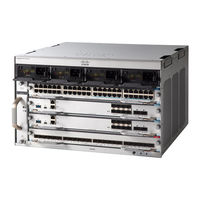
Cisco Catalyst 9400 Series System Management Configuration Manual (458 pages)
Cisco IOS XE Bengaluru 17.4.x
Brand:
Cisco
| Category:
Switch
| Size: 6.29 MB
Table of Contents
Table of Contents
4
Setting the System Clock
28
Configuring the Time Zone
29
Configuring Summer Time (Daylight Saving Time)
30
Configuring NTP
32
Default NTP Configuration
32
Configuring NTP Authentication
32
Configuring Poll-Based NTP Associations
34
Configuring Broadcast-Based NTP Associations
36
Configuring NTP Access Restrictions
37
Configuring a System Name
39
Setting up DNS
40
Configuring a Message-Of-The-Day Login Banner
42
Configuring a Login Banner
43
Managing the MAC Address Table
44
Changing the Address Aging Time
44
Configuring MAC Address Change Notification Traps
45
Configuring MAC Address Move Notification Traps
47
Configuring MAC Threshold Notification Traps
49
Disabling MAC Address Learning on VLAN
51
Adding and Removing Static Address Entries
52
Configuring Unicast MAC Address Filtering
54
Monitoring and Maintaining Administration of the Device
54
Configuration Examples for Device Administration
55
Example: Setting the System Clock
55
Examples: Configuring Summer Time
56
Example: Configuring a MOTD Banner
56
Example: Configuring a Login Banner
56
Example: Configuring MAC Address Change Notification Traps
57
Example: Configuring MAC Threshold Notification Traps
57
Example: Adding the Static Address to the MAC Address Table
57
Example: Configuring Unicast MAC Address Filtering
58
Additional References for Device Administration
58
Feature History for Device Administration
58
CHAPTER 2 Performing Device Setup Configuration
59
Restrictions for Performing Device Setup Configuration
59
Information about Performing Device Setup Configuration
59
Device Boot Process
59
Software Install Overview
60
Software Boot Modes
61
Installing the Software Package
62
Terminating a Software Install
62
Devices Information Assignment
62
Default Switch Information
63
DHCP-Based Autoconfiguration Overview
63
DHCP Client Request Process
64
DHCP-Based Autoconfiguration and Image Update
65
Restrictions for DHCP-Based Autoconfiguration
65
DHCP Autoconfiguration
65
DHCP Auto-Image Update
65
DHCP Server Configuration Guidelines
66
Purpose of the TFTP Server
66
Purpose of the DNS Server
67
How to Obtain Configuration Files
67
How to Control Environment Variables
68
Common Environment Variables
69
Environment Variables for TFTP
70
Scheduled Reload of the Software Image
71
How to Perform Device Setup Configuration
71
Configuring DHCP Autoconfiguration (Only Configuration File)
71
Configuring DHCP Auto-Image Update (Configuration File and Image)
73
Configuring the Client to Download Files from DHCP Server
76
Manually Assigning IP Information to Multiple Svis
77
Modifying Device Startup Configuration
79
Specifying a Filename to Read and Write a System Configuration
79
Manually Booting the Switch
80
Booting the Device in Installed Mode
81
Booting a Device in Bundle Mode
83
Configuring a Scheduled Software Image Reload
84
Configuration Examples for Device Setup Configuration
85
Examples: Displaying Software Bootup in Install Mode
85
Example: Managing an Update Package
88
Verifying Software Install
100
Example: Configuring a Device as a DHCP Server
103
Example: Configuring DHCP Auto-Image Update
104
Example: Configuring a Device to Download Configurations from a DHCP Server
104
Example: Scheduling Software Image Reload
104
Additional References for Performing Device Setup
105
Feature History for Performing Device Setup Configuration
105
CHAPTER 3 Smart Licensing Using Policy
107
Introduction to Smart Licensing Using Policy
107
Information about Smart Licensing Using Policy
108
Overview
108
Architecture
108
Product Instance
108
Cslu
109
Cssm
109
Controller
110
SSM On-Prem
110
Concepts
111
License Enforcement Types
111
License Duration
112
Authorization Code
112
Policy
112
RUM Report and Report Acknowledgement
114
Trust Code
114
Supported Topologies
115
Connected to CSSM through CSLU
115
Connected Directly to CSSM
116
Connected to CSSM through a Controller
118
CSLU Disconnected from CSSM
119
No Connectivity to CSSM and no CSLU
120
Supported Products
121
Interactions with Other Features
122
High Availability
122
Upgrades
123
Downgrades
125
How to Configure Smart Licensing Using Policy: Workflows by Topology
128
Workflow for Topology: Connected to CSSM through CSLU
128
Workflow for Topology: Connected Directly to CSSM
130
Workflow for Topology: Connected to CSSM through a Controller
131
Workflow for Topology: CSLU Disconnected from CSSM
132
Workflow for Topology: no Connectivity to CSSM and no CSLU
135
Migrating to Smart Licensing Using Policy
136
Example: Smart Licensing to Smart Licensing Using Policy
136
Example: RTU Licensing to Smart Licensing Using Policy
142
Example: SLR to Smart Licensing Using Policy
146
Example: Evaluation or Expired to Smart Licensing Using Policy
153
Task Library for Smart Licensing Using Policy
156
Logging into Cisco (CSLU Interface)
156
Configuring a Smart Account and a Virtual Account (CSLU Interface)
156
Adding a Product-Initiated Product Instance in CSLU (CSLU Interface)
157
Ensuring Network Reachability for Product Instance-Initiated Communication
157
Adding a CSLU-Initiated Product Instance in CSLU (CSLU Interface)
159
Collecting Usage Reports: CSLU Initiated
159
Download All for Cisco (CSLU Interface)
160
Upload from Cisco (CSLU Interface)
161
Ensuring Network Reachability for CSLU-Initiated Communication
161
Setting up a Connection to CSSM
165
Configuring Smart Transport through an Https Proxy
167
Configuring the Call Home Service for Direct Cloud Access
168
Configuring the Call Home Service for Direct Cloud Access through an Https Proxy Server
171
Removing and Returning an Authorization Code
172
Removing the Product Instance from CSSM
174
Generating a New Token for a Trust Code from CSSM
175
Installing a Trust Code
176
Downloading a Policy File from CSSM
177
Uploading Usage Data to CSSM and Downloading an ACK
177
Installing a File on the Product Instance
178
Setting the Transport Type, URL, and Reporting Interval
179
Configuring a License
181
Sample Resource Utilization Measurement Report
184
Troubleshooting Smart Licensing Using Policy
184
System Message Overview
184
System Messages
186
Additional References for Smart Licensing Using Policy
193
Feature History for Smart Licensing Using Policy
193
Configuring Application Visibility and Control in a Wired Network
195
Information about Application Visibility and Control in a Wired Network
195
Supported AVC Class Map and Policy Map Formats
195
Restrictions for Wired Application Visibility and Control
197
How to Configure Application Visibility and Control
199
CHAPTER 4 Configuring Application Visibility and Control in a Wired Network
199
Enabling Application Recognition on an Interface
199
Creating AVC Qos Policy
200
Applying a Qos Policy to the Switch Port
202
Configuring Wired AVC Flexible Netflow
203
NBAR2 Custom Applications
219
NBAR2 Dynamic Hitless Protocol Pack Upgrade
222
Monitoring Application Visibility and Control
224
Examples: Application Visibility and Control Configuration
224
Basic Troubleshooting - Questions and Answers
236
Additional References for Application Visibility and Control
237
Feature History for Application Visibility and Control in a Wired Network
237
CHAPTER 5 Environmental Monitoring and Power Management
239
About Environmental Monitoring
239
Using CLI Commands to Monitor Your Environment
239
Displaying Environment Conditions
240
Displaying on Board Failure Logging (OBFL) Information
241
Emergency Actions
242
System Alarms
243
Disabling Thermal Shutdown
244
Power Management
245
Power Supply Modes
245
Operating States
246
Show Power Detail
247
Power Management Considerations
249
Selecting a Power Supply Mode
250
Configuring the Redundant Mode
251
Configuring the Combined Mode
252
Power Budgeting for Supervisor Modules
253
Configuring the Power Budget Mode for a Single Supervisor
254
Moving from a Single to a Dual Supervisor Setup
254
Enabling Auto Line Card Shutdown
255
Powering down a Line Card
257
Configuration Examples for Power Supply Modes and Operating States
258
Example: Combined Mode and State (AC- and DC-Input)
258
Example: Combined Mode and State (DC-Input Only)
259
Normal Protected State
260
Example: N+1 Redundant Mode
262
Example: N+N Redundant Mode
263
State)
263
Example: N+N Redundant Mode
264
State)
264
Feature History for Environmental Monitoring and Power Management
266
CHAPTER 6 Configuring SDM Templates
267
Information about SDM Templates
267
SDM Templates and Switch Stacks
269
How to Configure SDM Templates
269
Setting the SDM Template
269
Monitoring and Maintaining SDM Templates
270
Configuration Examples for SDM Templates
271
Examples: Displaying SDM Templates
271
Examples: Configuring SDM Templates
275
Additional References for SDM Templates
275
Feature History for SDM Templates
275
CHAPTER 7 Configuring System Message Logs
277
Information about Configuring System Message Logs
277
System Messsage Logging
277
System Log Message Format
278
Default System Message Logging Settings
278
Syslog Message Limits
279
How to Configure System Message Logs
279
Setting the Message Display Destination Device
279
Synchronizing Log Messages
281
Disabling Message Logging
282
Enabling and Disabling Time Stamps on Log Messages
283
Enabling and Disabling Sequence Numbers in Log Messages
284
Defining the Message Severity Level
284
Limiting Syslog Messages Sent to the History Table and to SNMP
285
Logging Messages to a UNIX Syslog Daemon
286
Monitoring and Maintaining System Message Logs
287
Monitoring Configuration Archive Logs
287
Configuration Examples for System Message Logs
287
Example: Stacking System Message
287
Example: Switch System Message
288
Additional References for System Message Logs
288
Feature History for System Message Logs
288
CHAPTER 8 Configuring Online Diagnostics
289
Information about Configuring Online Diagnostics
289
Generic Online Diagnostics (GOLD) Tests
290
How to Configure Online Diagnostics
293
Starting Online Diagnostic Tests
293
Configuring Online Diagnostics
294
Scheduling Online Diagnostics
294
Configuring Health-Monitoring Diagnostics
295
Monitoring and Maintaining Online Diagnostics
297
Configuration Examples for Online Diagnostics
298
Examples: Start Diagnostic Tests
298
Example: Configure a Health-Monitoring Test
298
Example: Schedule Diagnostic Test
298
Example: Displaying Online Diagnostics
299
Additional References for Online Diagnostics
300
Feature Information for Configuring Online Diagnostics
300
CHAPTER 9 Managing Configuration Files
301
Prerequisites for Managing Configuration Files
301
Restrictions for Managing Configuration Files
301
Information about Managing Configuration Files
301
Types of Configuration Files
301
Configuration Mode and Selecting a Configuration Source
302
Configuration File Changes Using the CLI
302
Location of Configuration Files
302
Copy Configuration Files from a Network Server to the Device
303
Copying a Configuration File from the Device to a TFTP Server
303
Copying a Configuration File from the Device to an RCP Server
304
Copying a Configuration File from the Device to an FTP Server
305
Copying Files through a VRF
306
Copy Configuration Files from a Switch to Another Switch
306
Configuration Files Larger than NVRAM
307
Configuring the Device to Download Configuration Files
307
How to Manage Configuration File Information
308
Displaying Configuration File Information
308
Modifying the Configuration File
309
Copying a Configuration File from the Device to a TFTP Server
310
What to Do Next
311
Copying a Configuration File from the Device to an RCP Server
311
Examples
312
What to Do Next
313
Copying a Configuration File from the Device to the FTP Server
313
Examples
314
What to Do Next
315
Copying a Configuration File from a TFTP Server to the Device
315
What to Do Next
316
Copying a Configuration File from the Rcp Server to the Device
316
Examples
317
What to Do Next
317
Copying a Configuration File from an FTP Server to the Device
317
Examples
318
What to Do Next
319
Maintaining Configuration Files Larger than NVRAM
319
Compressing the Configuration File
319
Storing the Configuration in Flash Memory on Class a Flash File Systems
321
Loading the Configuration Commands from the Network
322
Copying Configuration Files from Flash Memory to the Startup or Running Configuration
323
Copying Configuration Files between Flash Memory File Systems
324
Copying a Configuration File from an FTP Server to Flash Memory Devices
325
What to Do Next
326
Copying a Configuration File from an RCP Server to Flash Memory Devices
326
Copying a Configuration File from a TFTP Server to Flash Memory Devices
327
Re-Executing the Configuration Commands in the Startup Configuration File
328
Clearing the Startup Configuration
328
Deleting a Specified Configuration File
329
Specifying the CONFIG_FILE Environment Variable on Class a Flash File Systems
330
What to Do Next
331
Configuring the Device to Download Configuration Files
332
Configuring the Device to Download the Network Configuration File
332
Configuring the Device to Download the Host Configuration File
333
Feature History for Managing Configuration Files
335
CHAPTER 10 Secure Copy
337
Prerequisites for Secure Copy
337
Information about Secure Copy
337
Secure Copy Performance Improvements
338
How to Configure Secure Copy
338
Configuring Secure Copy
338
Enabling Secure Copy on the SSH Server
339
Configuration Examples for Secure Copy
341
Example: Secure Copy Configuration Using Local Authentication
341
Example: Secure Copy Server-Side Configuration Using Network-Based Authentication
341
Additional References for Secure Copy
342
Feature Information for Secure Copy
342
CHAPTER 11 Configuration Replace and Configuration Rollback
343
Prerequisites for Configuration Replace and Configuration Rollback
343
Restrictions for Configuration Replace and Configuration Rollback
344
Information about Configuration Replace and Configuration Rollback
344
Configuration Archive
344
Configuration Replace
345
Configuration Rollback
346
Configuration Rollback Confirmed Change
346
Benefits of Configuration Replace and Configuration Rollback
346
How to Use Configuration Replace and Configuration Rollback
347
Creating a Configuration Archive
347
Performing a Configuration Replace or Configuration Rollback Operation
348
Monitoring and Troubleshooting the Feature
351
Configuration Examples for Configuration Replace and Configuration Rollback
353
Creating a Configuration Archive
353
Replacing the Current Running Configuration with a Saved Cisco IOS Configuration File
353
Reverting to the Startup Configuration File
354
Performing a Configuration Replace Operation with the Configure Confirm Command
354
Performing a Configuration Rollback Operation
354
Additional References for Configuration Replace and Configuration Rollback
355
Feature History for Configuration Replace and Configuration Rollback
356
CHAPTER 12 Performing Factory Reset
357
Prerequisites for Performing a Factory Reset
357
Restrictions for Performing a Factory Reset
357
Information about Performing a Factory Reset
357
How to Perform a Factory Reset
358
Configuration Examples for Performing a Factory Reset
360
Additional References for Performing a Factory Reset
363
Feature History for Performing a Factory Reset
363
CHAPTER 13 Configuring Secure Storage
365
Information about Secure Storage
365
Enabling Secure Storage
365
Disabling Secure Storage
366
Verifying the Status of Encryption
366
Feature Information for Secure Storage
367
CHAPTER 14 BIOS Protection
369
Introduction to BIOS Protection
369
ROMMON Upgrade
369
Capsule Upgrade
370
Feature History for BIOS Protection
370
CHAPTER 15 Software Maintenance Upgrade
373
Restrictions for Software Maintenance Upgrade
373
Information about Software Maintenance Upgrade
373
SMU Overview
373
SMU Workflow
374
SMU Package
374
SMU Reload
374
How to Manage Software Maintenance Updates
374
Installing an SMU Package
374
Managing an SMU Package
375
Configuration Examples for Software Maintenance Upgrade
376
Example: Managing an SMU
376
Additional References for Software Maintenance Upgrade
381
Feature History for Software Maintenance Upgrade
381
CHAPTER 16 Working with the Flash File System
383
Information about the Flash File System
383
Displaying Available File Systems
383
Setting the Default File System
386
Displaying Information about Files on a File System
386
Changing Directories and Displaying the Working Directory
388
Creating Directories
388
Removing Directories
389
Copying Files
389
Deleting Files
390
Creating, Displaying and Extracting Files
390
Additional References for Flash File System
392
Feature History for Flash File System
392
C H a P T E
395
Conditional Debug and Radioactive Tracing
395
Introduction to Conditional Debugging
395
Introduction to Radioactive Tracing
396
How to Configure Conditional Debug and Radioactive Tracing
396
Conditional Debugging and Radioactive Tracing
396
Location of Tracefiles
396
Configuring Conditional Debugging
397
Radioactive Tracing for L2 Multicast
398
Recommended Workflow for Trace Files
398
Copying Tracefiles off the Box
399
Monitoring Conditional Debugging
400
Configuration Examples for Conditional Debugging
400
Additional References for Conditional Debugging and Radioactive Tracing
401
Feature History for Conditional Debugging and Radioactive Tracing
401
CHAPTER 18 Consent Token
403
Restrictions for Consent Token
403
Information about Consent Token
403
Consent Token Authorization Process for System Shell Access
404
Feature History for Consent Token
405
C H a P T E
407
Troubleshooting the Software Configuration
407
Information about Troubleshooting the Software Configuration
407
Software Failure on a Switch
407
Lost or Forgotten Password on a Device
407
Power over Ethernet Ports
408
Disabled Port Caused by Power Loss
408
Disabled Port Caused by False Link-Up
409
Ping
409
Layer 2 Traceroute
409
Layer 2 Traceroute Guidelines
409
IP Traceroute
410
Time Domain Reflector Guidelines
411
Debug Commands
412
System Report
412
Onboard Failure Logging on the Switch
414
Fan Failures
415
Possible Symptoms of High CPU Utilization
415
How to Troubleshoot the Software Configuration
416
Recovering from a Software Failure
416
Recovering from a Lost or Forgotten Password
420
Procedure with Password Recovery Enabled
420
Procedure with Password Recovery Disabled
422
Preventing Switch Stack Problems
423
Preventing Autonegotiation Mismatches
424
Troubleshooting SFP Module Security and Identification
425
Monitoring SFP Module Status
425
Executing Ping
425
Monitoring Temperature
426
Monitoring the Physical Path
426
Executing IP Traceroute
426
Running TDR and Displaying the Results
426
Redirecting Debug and Error Message Output
427
Using the Show Platform Command
427
Using the Show Debug Command
427
Troubleshooting Packet Loss
427
Troubleshooting When Module Not Online
428
Troubleshooting Interface Problems
429
Troubleshooting When a Workstation Is Unable to Log in to the Network
429
Verifying Troubleshooting of the Software Configuration
430
Displaying OBFL Information
430
Example: Verifying the Problem and Cause for High CPU Utilization
430
Scenarios for Troubleshooting the Software Configuration
432
Scenarios to Troubleshoot Power over Ethernet (Poe)
432
Configuration Examples for Troubleshooting Software
434
Example: Pinging an IP Host
434
Example: Performing a Traceroute to an IP Host
435
Additional References for Troubleshooting Software Configuration
436
Feature History for Troubleshooting Software Configuration
436
CHAPTER 20 Recover from Corrupt or Missing File Image or in Rommon Mode
437
Introduction
437
Recover Switch from a Corrupt or Missing Image in Rommon Mode
438
Recover Switch from a Continous Reboot
439
Recover from a Corrupt or Missing Image
442
Feature Information for Recovering a Switch
449
Chapter 21
451
Line Auto Consolidation
451
Feature History for Line Auto Consolidation
457
Advertisement
Cisco Catalyst 9400 Series Hardware Installation Manual (192 pages)
Brand:
Cisco
| Category:
Switch
| Size: 11.86 MB
Table of Contents
Table of Contents
2
Chapter 1
7
Safety Warnings
7
Rack Units
10
CHAPTER 2 Product Overview
11
Switch Models
11
Catalyst 9404R Switch
11
Operations
11
Catalyst 9407R Switch
14
Catalyst 9410R Switch
18
Fan Tray Assembly
22
Fan Tray Assembly Overview
22
Operation
24
High Availability
24
Thresholds, Alarms, and Abnormal Acoustic Conditions
24
Power Supply Module
25
Power Supply Module Overview
25
Power Supply Modes
29
Power Supply Module Installation Considerations
30
CHAPTER 3 Preparing for Installation
33
Site Requirements
33
Temperature
34
Air Flow
34
Humidity
36
Altitude
36
Dust and Particles
36
Corrosion
37
EMI and Radio Frequency Interference
37
Shock and Vibration
38
Power Source Interruptions
38
System Grounding
39
Maintaining Safety with Electricity
40
Preventing ESD Damage
41
Power Requirements
42
Power Connection Guidelines for AC-Powered Systems
42
Power Connection Guidelines for DC-Powered Systems
43
Cabling Requirements
47
Rack-Mounting Guidelines
47
Site Preparation Checklist
49
Chapter 4
51
Standard Accessory Kit Contents
51
CHAPTER 5 Installing the Switch
53
Installation Tasks
53
Unpacking the Switch
55
Install the Switch as Shipped
56
Rack-Mounting the Chassis as Shipped
56
Install the Switch with Shelf Brackets
59
Shelf Kit Contents
59
Installing the Shelf Kit L Brackets
60
Installing the Shelf Brackets
63
Rack-Mounting the Chassis
65
Installing the Cable Guide
71
Installing the Cable Guide with Shelf Brackets
71
Installing the Cable Guide Without Shelf Brackets
74
Install the Switch in a NEBS-Compliant Mode
76
NEBS-Compliant Air Filter
76
Rack-Mounting the Chassis in a NEBS-Compliant Mode
77
Establishing System Ground
85
Attaching an ESD Strap
87
Verifying the Switch Chassis Installation
90
CHAPTER 6 Removing and Replacing Frus
91
Removing and Installing a Fan Tray
91
Enabling the Service Mode before Removing a Fan Tray
92
Removing a Fan Tray from the Front
92
Installing a Fan Tray from the Front
96
Removing a Fan Tray from the Rear
97
Installing a Fan Tray from the Rear
100
Verifying Fan Tray Installation
101
Removing and Installing a Power Supply Module
102
Removing and Installing an AC-Input Power Supply Module
104
Removing an AC-Input Power Supply Module
104
Installing an AC-Input Power Supply Module
108
Power Cord Retainer Mechanism
111
Removing and Installing a DC-Input Power Supply Module
116
Required Tools and Equipment
116
Removing a DC-Input Power Supply Module
117
Installing a DC-Input Power Supply Module
123
Removing and Installing a Power Supply Blank
131
Verifying the Power Supply Module Installation
133
CHAPTER 7 Troubleshooting
135
About this Section
135
System Boot Verification
135
Using Leds to Identify Startup Problems
136
System Messages
137
Troubleshooting with Software
137
Troubleshooting a Power Supply Module
138
Useful Cisco IOS Commands - Power Supply
138
Troubleshooting an AC-Input Power Supply
138
Troubleshooting a DC-Input Power Supply
139
Restoring the Default Mode of the Power Button for a DC Power Supply Module
140
Troubleshooting the Fan Tray Assembly
141
Useful Cisco IOS Commands - Fan Tray Assembly
143
Troubleshooting High Temperature Alarms
143
Troubleshooting the Switching Module
144
Useful Cisco IOS Commands - Switching Modules
144
Troubleshooting Supervisor Modules
144
Supervisor Module Leds
144
Standby Supervisor Engine Problems
144
Switch Self Reset
145
Cannot Connect to a Switch through the Console Port
145
Boot Problems
148
Contacting the Cisco Technical Assistance Center
148
CHAPTER 8 Specifications
149
Chassis Specifications
149
Catalyst 9404R Switch Chassis Specifications
149
Catalyst 9407R Switch Chassis Specifications
151
Catalyst 9410R Switch Chassis Specifications
153
Power Supply Specifications
154
2100-W AC-Input Power Supply Specifications
154
2100-W Power Supply Module AC Power Cords
156
3200-W AC-Input Power Supply Specifications
158
3200-W Power Supply Module AC Power Cords
160
3200-W DC-Input Power Supply Specifications
162
Chassis and Module Power and Heat Values
163
Weight Specifications
164
CHAPTER 9 Leds
167
Fan Tray Leds
167
Power Supply Leds
168
Cisco Catalyst 9400 Series Switching Module Leds
169
Cisco Catalyst 9400 Series Supervisor Module Leds
170
C H a P T E
173
Initial Configuration for the Switch
173
Options for Initial Configuration
173
Configuring the Switch Using the Web User Interface
173
Configuring the Switch Using the CLI
174
Starting the Terminal-Emulation Software
174
Connecting to a Power Source
174
Connecting the RJ-45 Console Port
175
Connecting the USB Console Port
175
IP Settings
176
Performing the Initial Configuration
176
Configuring the Switch in the ROMMON Mode
179
Installing and Uninstalling the USB Driver
180
Installing the Cisco Microsoft Windows USB Device Driver
180
Installing the Cisco Microsoft Windows 7 USB Driver
180
Uninstalling the Cisco Microsoft Windows USB Driver
180
Uninstalling the Cisco Microsoft Windows 7 USB Driver
180
Chapter 11
183
Related Documentation
183
Appendix A
185
Analysis of Cabling Requirements for IEEE 802.3Bt Type 4 Devices
185
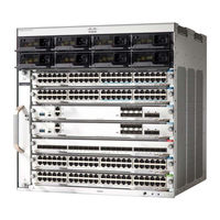
Cisco Catalyst 9400 Series Hardware Installation Manual (172 pages)
Brand:
Cisco
| Category:
Switch
| Size: 12.51 MB
Table of Contents
Table of Contents
2
Chapter 1
7
Safety Warnings
7
CHAPTER 2 Product Overview
9
Switch Models
9
Catalyst 9404R Switch
9
Catalyst 9407R Switch
14
Catalyst 9410R Switch
18
Fan Tray Assembly
23
Fan Tray Assembly Overview
23
Operation
24
High Availability
25
Thresholds, Alarms, and Abnormal Acoustic Conditions
25
Power Supply Module
26
Power Supply Module Overview
26
Power Supply Modes
28
Installation Considerations - Power Supply Modules of Different Capacities
29
CHAPTER 3 Preparing for Installation
31
Safety Warnings
31
Site Requirements
32
Temperature
33
Air Flow
33
Humidity
35
Altitude
35
Dust and Particles
35
Corrosion
36
EMI and Radio Frequency Interference
36
Shock and Vibration
37
Power Source Interruptions
37
System Grounding
37
Maintaining Safety with Electricity
39
Preventing Electrostatic Discharge Damage
40
Power Requirements
41
Cabling Requirements
42
Rack-Mounting Guidelines
42
Site Preparation Checklist
44
Chapter 4
47
Standard Accessory Kit Contents
47
CHAPTER 5 Installing the Switch
49
Installation Tasks
49
Unpacking the Switch
51
Install the Switch as Shipped
52
Rack-Mounting the Chassis as Shipped
52
Install the Switch with Shelf Brackets
55
Shelf Kit Contents
55
Installing the Shelf Kit L Brackets
56
Installing the Shelf Brackets
59
Rack-Mounting the Chassis
61
Installing the Cable Guide
67
Installing the Cable Guide with Shelf Brackets
67
Installing the Cable Guide Without Shelf Brackets
70
Install the Switch in a NEBS-Compliant Mode
72
NEBS-Compliant Air Filter
72
Rack-Mounting the Chassis in a NEBS-Compliant Mode
73
Establishing System Ground
80
Attaching an ESD Strap
82
Verifying the Switch Chassis Installation
83
CHAPTER 6 Removing and Replacing Frus
85
Removing and Installing the Fan Tray
85
Enabling the Service Mode before Removing the Fan Tray
86
Removing the Fan Tray from the Front
86
Installing the Fan Tray from the Front
89
Removing the Fan Tray from the Rear
90
Installing the Fan Tray from the Rear
93
Verifying Fan Tray Installation
94
Removing and Installing the Power Supply
95
Installing the Power Supply
95
Removing the Power Supply
98
Removing and Installing Power Supply Blanks
102
Power Cord Retainer Mechanism
104
Verifying the Power Supply Installation
109
CHAPTER 7 Troubleshooting
111
About this Section
111
System Boot Verification
111
Using Leds to Identify Startup Problems
112
System Messages
113
Troubleshooting with Software
113
Troubleshooting the Power Supply
113
Useful Cisco IOS Commands - Power Supply
114
Troubleshooting the Fan Tray Assembly
115
Useful Cisco IOS Commands - Fan Tray Assembly
116
Troubleshooting High Temperature Alarms
116
Troubleshooting the Switching Module
117
Useful Cisco IOS Commands - Switching Modules
117
Troubleshooting Supervisor Modules
117
Supervisor Module Leds
117
Standby Supervisor Engine Problems
117
Switch Self Reset
118
Cannot Connect to a Switch through the Console Port
119
Boot Problems
121
Contacting the Cisco Technical Assistance Center
121
CHAPTER 8 Specifications
123
Chassis Specifications
123
Catalyst 9404R Switch Chassis Specifications
123
Catalyst 9407R Switch Chassis Specifications
125
Catalyst 9410R Switch Chassis Specifications
126
Power Supply Specifications
128
3200 W AC-Input Power Supply Specifications
128
3200 W Power Supply AC Power Cords
129
2100 W AC-Input Power Supply Specifications
132
2100 W Power Supply AC Power Cords
133
Chassis and Module Power and Heat Values
136
Weight Specifications
137
CHAPTER 9 Leds
139
Fan Tray Leds
139
Power Supply Leds
140
Cisco Catalyst 9400 Series Switching Module Leds
140
Cisco Catalyst 9400 Series Supervisor Module Leds
141
C H a P T E
145
Initial Configuration for the Switch
145
Options for Initial Configuration
145
Configuring the Switch Using the Web User Interface
145
Setting up the Switch
145
Connecting to the Switch
146
Creating User Accounts
146
Choosing Setup Options
147
Configuring Basic Device Settings
147
Configuring Your Device Based on a Site Profile
148
Configuring Switch Wide Settings
154
Configuring VLAN Settings
154
Configure STP Settings
154
Configuring DHCP, NTP, DNS and SNMP Settings
155
Configuring Port Settings
156
Configuring the Switch Using the CLI
157
Starting the Terminal-Emulation Software
157
Connecting to a Power Source
158
Connecting the RJ-45 Console Port
159
Connecting the USB Console Port
159
IP Settings
160
Performing the Initial Configuration
160
Configuring the Switch in the ROMMON Mode
163
Installing and Uninstalling the USB Driver
164
Installing the Cisco Microsoft Windows USB Device Driver
164
Installing the Cisco Microsoft Windows XP USB Driver
164
Installing the Cisco Microsoft Windows 2000 USB Driver
164
Installing the Cisco Microsoft Windows Vista and Windows 7 USB Driver
165
Uninstalling the Cisco Microsoft Windows USB Driver
165
Uninstalling the Cisco Microsoft Windows XP and 2000 USB Driver
165
Uninstalling the Cisco Microsoft Windows Vista and Windows 7 USB Driver
166
Chapter 11
167
Related Documentation
167
Advertisement
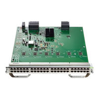
Cisco Catalyst 9400 Series Installation Note (32 pages)
Switching Module
Brand:
Cisco
| Category:
Control Unit
| Size: 2.92 MB
Table of Contents
Cisco Catalyst 9400 Series Module Installation Note
2
Importantes Informations de Sécurité
3
Viktiga Säkerhetsanvisningar
4
Cisco Catalyst 9400 Series Module Features
4
Status Led
6
Cisco Catalyst 9400 Series Switching Module Leds
22
Required Tools
23
Related Documentation
28
Notices
30
Cisco Catalyst 9400 Series Troubleshooting Manual (14 pages)
Brand:
Cisco
| Category:
Switch
| Size: 1.23 MB
Table of Contents
Table of Contents
1
About this Section
1
System Boot Verification
1
Using Leds to Identify Startup Problems
2
System Messages
3
Troubleshooting with Software
3
Troubleshooting a Power Supply Module
4
Troubleshooting the Fan Tray Assembly
7
Troubleshooting High Temperature Alarms
9
Troubleshooting the Switching Module
10
Troubleshooting Supervisor Modules
10
Contacting the Cisco Technical Assistance Center
14
Advertisement
Related Products
Cisco Catalyst 9404R Switch
Cisco Catalyst 9407R
Cisco Catalyst 9410R
Cisco 9124 - mds multilayer fabric switch
Cisco Nexus 93180YC-EX
Cisco Nexus 9236C
Cisco Catalyst 9606R
Cisco Nexus 9272Q
Cisco Nexus 93120TX
Cisco Nexus 93216TC-FX2
Cisco Categories
Switch
IP Phone
Network Router
Wireless Access Point
Conference System
More Cisco Manuals
Login
Sign In
OR
Sign in with Facebook
Sign in with Google
Upload manual
Upload from disk
Upload from URL