Bard Q-TEC Series Manuals
Manuals and User Guides for Bard Q-TEC Series. We have 9 Bard Q-TEC Series manuals available for free PDF download: Literature Assembly, Installation Instructions Manual
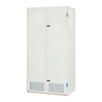
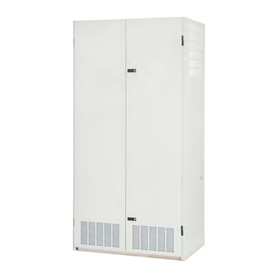
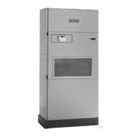
Bard Q-TEC Series Literature Assembly (137 pages)
Brand: Bard
|
Category: Air Conditioner
|
Size: 3.67 MB
Table of Contents
Advertisement

Advertisement
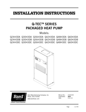
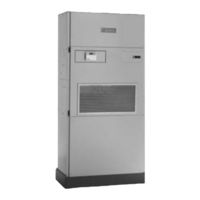
Bard Q-TEC Series Installation Instructions Manual (41 pages)
PACKAGED AIR CONDITIONER
Brand: Bard
|
Category: Air Conditioner
|
Size: 1.54 MB
Table of Contents


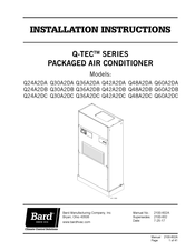
Bard Q-TEC Series Installation Instructions Manual (38 pages)
Packaged Air Conditioner
Brand: Bard
|
Category: Air Conditioner
|
Size: 1.58 MB
Table of Contents

Advertisement