Sign In
Upload
Manuals
Brands
Bard Manuals
Air Conditioner
Q-TEC Q A4D Series
Bard Q-TEC Q A4D Series Manuals
Manuals and User Guides for Bard Q-TEC Q A4D Series. We have
1
Bard Q-TEC Q A4D Series manual available for free PDF download: Installation Instructions Manual
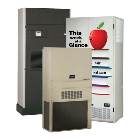
Bard Q-TEC Q A4D Series Installation Instructions Manual (97 pages)
Packaged Air Conditioner
Brand:
Bard
| Category:
Air Conditioner
| Size: 4.22 MB
Table of Contents
User's Application Guide and Technical Product Overview
4
Table of Contents
4
Overview
5
Documentation
6
Unit Literature Assembly - Documentation Provided with Your Units
6
Unit Installation
7
WALL MOUNT Products - Mounting the Product on Wall Surface
7
WALL MOUNT Products - Clearances for Outdoor Condenser Fan Airflow
8
WALL MOUNT Products - Clearances for Indoor Supply and Return Airflow
8
WALL MOUNT Products - Condensate and Defrost Drainage
9
I-TEC and Q-TEC Products - Installing the Product Inside a Room
10
I-TEC and Q-TEC Products - Clearances for Outdoor Condenser Fan Airflow
10
I-TEC and Q-TEC Products - Clearances for Indoor Supply and Return Airflow
11
I-TEC Air Path
11
Q-TEC Air Path
11
I-TEC and Q-TEC Products - Condensate Drainage
12
All Products - Power Supply Verification
13
Field-Supplied Voltage
13
Hertz (Frequency)
13
Single and Three Phase Power
13
Unit Maintenance
14
All Products - Filters and Filter Servicing
14
Outdoor Unit Wall Mount Room Air Filters
14
WALL MOUNT Products - Filters and Filter Servicing
15
I-TEC Indoor Products - Filters and Filter Servicing
16
Q-TEC Indoor Products - Filters and Filter Servicing
17
All Products - Coil Cleaning
18
Equipment Corrosion Protection
18
All Products - Condenser Airflow
19
Unit Operation
20
Air-To-Air Cooling Products (Air Conditioners)
20
Air-To-Air Cooling and Heating Products (Heat Pumps)
20
Cooling Mode
20
Heating Mode
20
Water-To-Air Cooling and Heating Products (Geothermal Heat Pumps)
21
Cooling Mode
21
Water Supply Systems
21
Dehumidification and Ventilation Operation
22
Dehumidification (Air-To-Air or Water-To-Air Systems)
22
Ventilation Options (Air-To-Air or Water-To-Air Systems)
22
Troubleshooting
23
All Units - Troubleshooting
23
Table of Contents
26
Getting Other Information and Publications
28
Q-TEC Model Nomenclature
29
Shipping Damage
29
Unit Removal from Skid
30
Air Seal under Q-TEC Unit
30
Removal of Q-TEC Unit from Skid
30
General
31
Handling Unit after Removal from Skid
31
Fan Assembly Removal
31
Q-TEC Unit on Appliance Cart
31
Installation with Duct-Free Plenum
32
Minimum Installation Height
32
Ducted Application
32
Duct Work
33
Filters
33
Supply Duct Connections
33
Filter Location
33
Switching Filter Sizes
34
Fresh Air Intake
34
Vent Options
34
Barometric Fresh Air Damper (Standard)
34
Bend Filter Tabs down
34
Filter Tabs in up Position
34
Fresh Air Damper Assembly
34
Commercial Room Ventilator (Option)
35
Q-TEC Energy Recovery Ventilator (Option)
35
Installation
36
Basic Installation Design and Application Planning
36
Mounting the Unit
36
Remove Compressor Shipping Brackets
36
Figure 13A
37
Figure 13B
37
Condensate Drain
38
Remove Locking Screws from Wheels
38
Optional Side Drain (Side View)
38
Standard Rear Drain
38
Optional Rear Drain Kits
39
Rear Drain (Top View)
39
Figure 18A
40
Figure 18B
40
Figure 18C
41
Figure 18D
42
Ducted Applications
43
Free Blow Applications
43
Indoor Ducted and Non-Ducted Applications
43
Indoor Return Airflow
43
Indoor Supply Airflow
43
Placement
43
Figure 7 Figure
44
Unit Dimensions
44
High Voltage Connections
45
Wiring - Main Power
45
Balanced Climate TM Feature
46
Dehumidification Feature
46
Low Ambient Control
46
Low Voltage Connections
46
Unit Shutdown Feature
46
Ventilation Features
46
Wiring - Low Voltage
46
CO 2 Controllers
47
Freeze Protection Thermostat
47
Humidity Controls
47
Wall Thermostats
47
Thermostat Wire Size
47
Figure 21
48
Figure 21 Thermostat Connections
48
Figure 22 Thermostat Connections
49
Start up
50
General
50
Topping off System Charge
50
Safety Practices
50
Vent Connection Plug
50
Pressure Service Ports
50
Important Installer Notes
51
Service Hints
51
High and Low Pressure Switches
51
Three Phase Scroll Compressor Start up
51
Information
51
Compressor Control Module
51
Dehumidification Models
51
Pressure Switch Lockout
51
Alarm Output
52
Figure 23
52
Figure 23 Compressor Logic Control Board
52
Freeze Stat Switch
52
High Pressure Switch
52
High Pressure Switch and Lockout Sequence
52
Intelligent Reset
52
Low Pressure Switch
52
Over and under Voltage Protection
52
Troubleshooting Compressor Logic CCM
52
Logic Control Board
53
Phase Monitor
53
Condenser Fan Operation
53
Sequence of Operation
53
Figure 24 CCM LED Fault Illumination
53
Balanced Climate TM Mode
54
Service
55
Troubleshooting ECM 142R Outdoor
55
Fan Motors
55
Replacing the Motor
56
Troubleshooting ECM 142R Outdoor Fan Motors
56
Troubleshooting ECM Indoor Blower Motors
57
Figure 25 Control Disassembly
58
Figure 26 Winding Test
58
Figure 27 Drip Loop
58
Replacing ECM Control Module
58
Figure 28 Control Connector Motor Half
59
Figure 9 Figure
59
Table 6
59
Fan Blade Dimensions
60
Fan Blade Setting Dimensions
60
Figure 29 Fan Blade Setting
60
Figure 30 Fan Shroud Removal
60
R-410A Refrigerant Charge
60
Removal of Fan Shroud
60
Cooling Pressure - Standard Airflow
61
Table 8A
61
Cooling Pressure - Balanced Climate Airflow
61
Table 9
62
Electrical Specifications Q**A4D Series
62
Table 10
63
Indoor Blower Performance
63
Electric Heat
63
Graphs
64
Graph 1
64
Q36A4D FAD Ventilation Delivery
64
Q42A4D FAD Ventilation Delivery
64
Graph 3
65
Q48A4D FAD Ventilation Delivery
65
Table 2
88
Advertisement
Advertisement
Related Products
Bard QA421D
Bard QA481D
Bard QTEC QA421 Series
Bard QTEC QA481 Series
Bard QA241D
Bard QA361D
Bard QA601D
Bard QTEC QA301 Series
Bard QTEC QA361 Series
Bard QA301D
Bard Categories
Air Conditioner
Heat Pump
Medical Equipment
Furnace
Controller
More Bard Manuals
Login
Sign In
OR
Sign in with Facebook
Sign in with Google
Upload manual
Upload from disk
Upload from URL