Sign In
Upload
Manuals
Brands
Bard Manuals
Air Conditioner
FUSION-TEC WR Series
Bard FUSION-TEC WR Series Manuals
Manuals and User Guides for Bard FUSION-TEC WR Series. We have
2
Bard FUSION-TEC WR Series manuals available for free PDF download: Literature Assembly, Service Instructions Manual
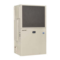
Bard FUSION-TEC WR Series Service Instructions Manual (56 pages)
Wall-Mount
Brand:
Bard
| Category:
Air Conditioner
| Size: 2.06 MB
Table of Contents
Table of Contents
2
Using the TEC-EYE
6
Figure 2 TEC-EYE Connection to Unit Control
6
TEC-EYE Screen Structure and Password Level
7
TEC-EYE Acronyms
7
Main Status Screen
7
Quick Menu
8
Figure 3 Quick Menu Icons
8
Figure 4 Cool and Heat Setpoints
8
Figure 5 Orphan Mode Staging
8
Figure 6 Master Staging
8
Information
8
Master Staging
8
Orphan Mode Staging
8
Setpoints
8
Staging Information
8
A/C Circuit Measurements
9
Component Lifetime Hours
9
Figure 7 A/C Circuit Measurements
9
Figure 8 Last 24 Operation
9
Figure 9 Software Version
9
Last 24 Hour Operation
9
Software Version
9
Software Versioning Guide
9
Alarm Log
10
Addressing Wall-Mount Units
10
Executing a Run Test
10
Figure 10 Changing Unit Address
10
Figure 11 Executing Run Test
10
Figure 12 Run Test Summary
10
Run Test Parameter Descriptions
11
Reset to Factory Defaults
11
Figure 13 Run Test: Motors & Sensors
11
Figure 14 Run Test: A/C Circuit
11
Figure 15 Restoring Factory Default Settings
11
Figures and Tables Figure 1 TEC-EYE Display and Interface
6
TEC-EYE Hand-Held Diagnostic Tool
6
Using the TEC-EYE TM
6
Alarm Adjustment
12
Acknowledging Alarms
12
Clearing Alarms
12
Clearing Alarm Logs and Counters
12
Exporting Alarm Logs
12
Figure 16 Clearing All Alarms
12
Figure 17 Clearing Alarm Logs and Counters
12
Exporting 7 Day Logs
13
Operation
12
Unit On/Off
12
Orphan Model
13
Temperature/Humidity Control
13
Temperature/Humidity Control Components
13
Figure 18 Changing Zone
13
Figure 19 Adjusting Return Air Sensor
13
Return Air Temperature Sensor
13
Return Air Temperature Alarm
14
Temperature/Humidity Control Operation
14
Cooling Sequence: Economizer Available
14
Economizer Operation in Orphan Mode
14
Figure 20 Staging
14
Adjusting Cooling Staging
15
Cooling Sequence: Economizer Not Available
15
Figure 21 Enabling Free Cooling Delay
15
Figure 22 Viewing Unit Stages
15
Heating Sequence
15
Staging
15
Adjusting Heating Staging
16
Dehumidification
16
Dehumidification Modes
16
Figure 23 Adjusting Cooling Stage Differentials
16
Figure 24 Adjusting Heating Stage Differentials
16
Cycling Dehumidification Operation
17
Zone
13
Electronic Expansion Valve (EEV)
17
EEV Components
17
EEV Instructions for Vacuum, Reclaim, Charge Unit
17
Electronic Expansion Valve
17
Figure 25 Overriding EEV Output
18
Figure 26 Electronic Expansion Valve and Service Tool
18
Suction Pressure Transducer
18
System Pressures
18
Evaporator Freeze Condition Alarm
19
Figure 28 Voltage/Pressure: Suction Pressure Transducer
19
Suction Pressure Alarm
19
Suction Temperature Alarm
19
Suction Temperature Sensor
19
Troubleshooting the Suction Pressure Transducer
19
EEV Operation
20
EEV Superheat Control
20
Additional EEV Alarms
20
Low Superheat Alarm
20
Indoor Airflow
20
Indoor Airflow Components
20
Blower
20
Figure 30 Adjusting Freeze Setpoint and Alarm Delay
20
Figure 31 Putting Blower Output into Override Mode
20
Blower Status Alarm
22
Blower Status Switch
22
Dirty Filter Switch
22
Figure 32 Dirty Filter Switch/Blower Status Switch
22
Figure 33 Verifying Differential Airflow Status
22
Figure 34 Adjusting Air Flow Alarm Delay
22
Filters
22
Dirty Filter Alarm
23
Filter Indicator Light
23
Indoor Airflow Operation
23
Figure 35 Enabling High Sensible Mode
23
High Sensible Mode
23
Blower Speed Control
24
Additional Indoor Airflow Alarms
24
Supply Air Temperature Alarm
24
Condenser Fan
24
Condenser Fan Components
24
Figure 36 Dirty Filter Switch and Filter Indicator Light
24
Figure 37 Verifying Condenser Fan Output
25
Figure 38 Fan Blade Setting
25
Figure 39 Adjusting Liquid Pressure Transducer Values
25
Liquid Line Pressure Transducer
25
Troubleshooting the Liquid Pressure Transducer
25
Liquid Pressure Transducer Alarm
26
Liquid Temperature Sensor
26
Condenser Fan Operation
26
Condenser Fan Speed
26
Condenser Fan Speed Control
26
Figure 40 Voltage/Pressure: Liquid Pressure Transducer
26
Figure 41 Adjusting Liquid Temperature Values
26
High Pressure Control
26
Low Ambient Control
26
Second Stage Drop out
26
Compressor
27
Compressor Components
27
Compressor Control Module (CCM)
27
Delay-On-Make Timer
27
Figure 42 Liquid Pressure Control Setpoint
27
Brownout Protection W/Adjustment
28
Figure 43 8201-169 Compressor Control Module
28
High Pressure Detection
28
Short Cycle Protection/Delay-On-Break
28
Test Mode
28
High Pressure Safety Switch
29
Phase Monitor
29
Refrigerant High Pressure Alarm
29
Compressor Operation
29
Figure 44 Adjusting Compressor Delays
29
Compressor Low Temperature Limit
30
Additional Compressor Alarms
30
Refrigerant Low Pressure Alarm
30
Economizer
30
Economizer Components
30
Actuator
30
Figure 45 Adjusting Compressor Low Temp Limit
30
Figure 46 Adjusting Low Pressure Alarm Settings
30
Dust Sensor
31
Dust Sensor Failure Alarm
31
Figure 47 Damper Output and Override
31
Figure 48 Dust Sensor
31
High Dust Limit Alarm
31
Damper Blade
32
Damper Switch
32
Figure 49 Adjusting Dust Sensor Alarm Setpoint
32
Figure 50 Adjusting Minimum Damper Position
32
Minimum Damper Position
32
Damper Failed to Close Alarm
33
Damper Failed to Open Alarm
33
Figure 51 Damper Switch
33
Figure 52 Adjusting Damper Alarm Delay
33
Outdoor Temperature and Humidity Combination Sensor
33
Figure 53 Outdoor Air Sensor
34
Figure 54 Outdoor Humidity Sensor
34
Figure 55 Supply Air Sensor
34
Outdoor Humidity Sensor Failure Alarm
34
Outdoor Temperature Sensor Failure Alarm
34
Supply Temperature Sensor
34
Supply Temperature Sensor Failure Alarm
34
High Supply Air Temperature Alarm
35
Low Supply Air Temperature Alarm
35
Economizer Operation
35
Figure 56 Adjusting Supply Air Temperature Differential
35
Figure 57 Economizer Setup A2
35
Figure 58 Economizer Setup A3
36
Bard Guard Anti-Theft System Option
37
Electric Heat Option
37
Electric Heat Components
37
Electric Heating Element
37
Thermal Overload
37
Electric Heat Operation
37
Emergency Cooling Mode
37
Emergency Ventilation Mode
37
Model/Serial Number Configuration
37
Inverter Option
38
Unit Disable Option
38
Figure 59 FUSION-TEC WR Series Unit Control Board
39
Figure 60 FUSION-TEC WR Series Nomenclature
41
General
42
Important Installer Note
42
Pressure Service Ports
42
R410-A Refrigerant Charge
42
Refrigerant Information
42
Safety Practices
42
Topping off System Charge
42
Bard Guard Anti-Theft System Option
44
Maintenance
44
Standard Maintenance Procedures
44
8301-067 Outdoor Temperature/Humidity Sensor
45
8301-067 Sensor Connections
45
Figure 61 8301-067 Sensor Electrical Connections
45
Figure 62 8301-067 Sensor Terminal Connections
45
8301-067 Humidity Sensor Test Value Outputs
48
8301-067 Humidity Sensor Calibration
48
Figure 63 8301-067 DIP Switch/Output Configuration
48
Troubleshooting
45
8301-057 Blower Status Switch/Dirty Filter Switch
49
Figure 64 8301-057 Air Differential Switch Terminals
49
8301-073 Dust (Particulate) Sensor
50
8612-061 Dust (Particulate) Sensor Control Board
51
8612-061 Control Board Output Signal Not Responsive to Dust
51
Figure 65 8612-061 Dust Sensor Alarm Board
51
Figure 66 Dust Sensor Alarm Board Power Supply Check
52
8408-044 Return Air Sensor/Suction Sensor
53
8301-066 Supply Air Sensor
54
8406-157 Liquid Line Pressure Transducer
55
8406-158 Suction Pressure Transducer
56
Advertisement
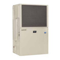
Bard FUSION-TEC WR Series Literature Assembly (102 pages)
СSystem/Wall-Mount Air Conditioner with LC6000-200 Supervisory Controller
Brand:
Bard
| Category:
Air Conditioner
| Size: 3.74 MB
Table of Contents
Section 1
4
Table of Contents
4
General Information
6
Air Conditioning System
6
Wall-Mount Air Conditioner Units
6
Controller
6
General
7
Shipping Damage
7
Additional Publications
7
List of Necessary Materials/Tools
8
Figure 1
9
Site Preparation
9
Model Identification
9
New Shelter Installation Vs. Retrofit Installation
9
Minimum Clearance
10
Clearance to Combustibles
10
Wall-Mount Unit Mounting
12
Mounting the Units
12
Figure 3
13
Supply Air Grill Installation
14
Figure 5
14
Wall-Mount Unit Wiring
20
Main Power Wiring
20
Figure 18
22
Unit Control Voltage Wiring
22
Figure 19
24
Running in Orphan Mode
24
Preliminary Start up
24
Figure 20
25
Figure 21
26
LC6000 Controller
26
Mounting the LC Controller
26
Figure 22
27
Installing Remote Indoor Temperature/Humidity Sensor(S)
27
Figure 23
28
Sensor
28
Figure 25
30
Generator Run Connections
30
Communication Wiring
31
Figure 28
32
Figure 30
34
Figure 31
35
Figure 32
36
Supply Wiring
36
Figure 34
38
LC6000 Controller Installation
25
Figure 36
39
Tec-Eye Status Screen
39
TEC-EYE TM Hand-Held Diagnostic Tool
39
Setting up Wall-Mount Units for Operation
40
Figure 43
42
Setting up LC6000 for Operation
42
System Set up
39
1 Address each Wall-Mount Unit
40
2 Execute a Run Test on each Unit
40
Figure 37
40
3 Clear Unit Alarm Logs on each Unit
41
Figure 39
41
LC6000 Controller Display/Interface
42
Setting Controller Date and Time
42
Enable/Disable Zone 1 Indoor Temperature Sensor
43
Enable/Disable Zone 2 Indoor Humidity Sensor
43
Enable/Disable Zone 3 Indoor Humidity Sensor
43
Figure 45
43
Enable/Disable Zone 1 Indoor Humidity Sensor
43
Enable/Disable Zone 1 Remote Temperature Sensor
44
Enable/Disable Zone 2 Remote Temperature Sensor
44
Enable/Disable Zone 3 Remote Temperature Sensor
44
4 Set LC Controller Date and Time
42
5 Configure Sensors
42
6 Enter Total Number of Units
45
Figure 49
44
Enable/Disable Outdoor Air Humidity Sensor
45
Figure 52
45
Enable/Disable Outdoor Air Temperature Sensor
45
7 Verify Units Are Online
45
8 Select Economizer Type for each Zone
45
Total Units Displayed
45
9 Clear Controller Alarm Logs
46
10 Complete Installation
46
Figure 56 Clearing LC6000 Alarm Logs
46
Selecting Economizer Type
46
Additional Information
47
Menu Screens and Password Levels
47
Calibrating Sensors
47
Figure 58 Current Sensor Orientation
47
Remote Indoor Temperature/Humidity Sensor
49
Figure 59 Earlier Sensor Orientation
49
Section 2
55
General Information
56
Air Filters
56
Outdoor Coil
56
Routine Equipment Outdoor Maintenance
57
Basic Operating Principles
57
Air Conditioners
57
Heat Pump (Air-To-Air)
58
Heat Pump (Water-To-Air)
59
Ventilation
60
Dehumidification Circuits
60
Automatic Control Systems
60
Thermostats
60
Humidistats (Humidity Controllers)
60
Insufficient Cooling or Heating
61
Failure to Operate
61
Lubrication Requirements
61
Periodic Maintenance
61
Helpful Hints & Operating Practices
62
Figure 42 Clearing Unit Alarm Logs
65
General
66
Attaching Gauge Manifold
66
Gauge Manifold
66
Leak Detectors
66
Recovery Equipment Rated for R-410A
66
Attaching Manifold Hose to Schrader Valve
67
Evacuation
67
Leak Test
67
Charging
68
Charging the System by Weight
68
Preliminary Charging Steps
68
Air Conditioning & Heat Pump - Cooling
72
Heat Pump - Heating
72
High Suction - High Head Pressure
72
High Suction - Low Head Pressure
72
Low Suction - High Head Pressure
72
Low Suction - Low Head Pressure
72
Replacement Parts Manual
76
Cabinet Components
77
Functional Components
81
Control Panel - 1 Phase
85
Control Panel - 3 Phase
87
Blower Assembly Components - WR35BP
89
Blower Assembly Components - WR36BP
90
Blower Assembly Components - WR58BP
91
Description
91
Heater Packages - WR35BP
92
Heater Packages - WR36BP*/WR58BP
93
Freecooling Damper Motor
94
Anti-Theft Kit (Optional)
95
Manual: 2110-1547E
95
Date
97
Advertisement
Related Products
Bard Fusion-Tec
Bard FUSION-TEC HR Series
Bard FC085D36F
Bard FH085D36E
Bard FLF110D48E
Bard FH110D48D
Bard FLF110D48D
Bard FLR110D48D
Bard FLR110V60A
Bard FH085V42A
Bard Categories
Air Conditioner
Heat Pump
Medical Equipment
Furnace
Controller
More Bard Manuals
Login
Sign In
OR
Sign in with Facebook
Sign in with Google
Upload manual
Upload from disk
Upload from URL