Sign In
Upload
Manuals
Brands
APRILIA Manuals
Motorcycle
DORSODURO 1200 ABS - ATC
APRILIA DORSODURO 1200 ABS - ATC Manuals
Manuals and User Guides for APRILIA DORSODURO 1200 ABS - ATC. We have
1
APRILIA DORSODURO 1200 ABS - ATC manual available for free PDF download: Service Station Manual
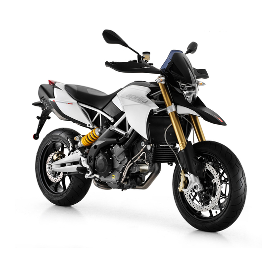
APRILIA DORSODURO 1200 ABS - ATC Service Station Manual (409 pages)
Brand:
APRILIA
| Category:
Motorcycle
| Size: 15.23 MB
Table of Contents
Index of Topics
5
Characteristics
8
Rules
8
Safety Rules
8
Maintenance Rules
9
Running-In
11
Chassis Number
12
Dimensions and Mass
12
Engine Number
12
Vehicle Identification
12
Capacities
13
Engine
13
Transmission
13
Drive Chain
14
Electrical System
14
Frame and Suspensions
14
Brakes
15
Wheels and Tyres
15
Chassis
16
Front Side
16
Supply
16
Tightening Torques
16
Oil Cooling Radiator
17
Front Fork
18
Steering
18
Instrument Panel
19
Front Mudguard
20
Handlebar
20
Clutch Pump
21
Front Brake Pump
22
Headlamp
23
Front Bodywork
24
Front Wheel
25
Central Part
26
Description
26
Front Brake
26
Front Chassis
26
M8X20
26
Nm (59 Lbf Ft)
26
Centre Frame
27
Footrests
28
Stand Assembly
28
Fuel Tank
29
Loctite 518
29
Air Filter Box
30
Fuel Pump
30
Locks
33
Saddle Mounting
34
Throttle Body
34
Swingarm
35
Rear Suspension
36
Exhaust System
37
Rear Wheel
37
Rear Brake
38
Tail Light
39
Rear Bodywork
40
ABS System
42
Head
43
Head Cover
43
Cylinder
44
Timing System
45
Crankshaft
46
Oil Pump
47
Gear Selector
48
Clutch Cover
49
Clutch
50
Water Pump
50
Ignition
51
Crankcase
52
Assembly Clearances
53
Crankcase - Crankshaft - Connecting Rod
53
Cylinder - Piston Assy
53
Overhaul Data
53
Crankcase Classes
54
Internal Marking on Second Generation Crankcases
54
Crankshaft Classes
55
Main Bushings
55
Bushings
57
Connecting Rods
57
Shaft Category
57
Recommended Products Chart
58
Special Tools
60
Maintenance Chart
67
Routine Maintenance Table
67
Front Spark Plug
68
Rear Spark Plug
69
Check
70
Engine Oil
70
Replacement
71
Engine Oil Filter
72
Air Filter
73
Checking the Valve Clearance
74
Troubleshooting
78
RUN/STOP Switch
81
Check Fuel Pump
82
Diagnosis Instrument Connection Check
82
Electrical System Installation
82
Auxiliary Injection Relay 31 Check
83
Main Injection Relay 17 Check
84
Starter Button Check
84
Components Arrangement
88
Auxiliary Injection Relay
89
Light Logic Relay
89
Main Injection Relay
89
Start-Up Relay
89
Fan Control Relay
90
High Beam Lights Relay
90
Recovery Logic Relay
90
Motorcycle Division
91
Special Checks for the Correct Connection and Laying of Cables
91
Back Side
110
General Wiring Diagram
114
Checks and Inspections
117
Conceptual Diagrams
117
Connector Check Procedure
117
Continuity Check
117
Ground Conection Check
118
Immobiliser
118
System Components
118
Voltage Check
118
Instrument Panel: Errors
119
Dashboard
120
Diagnosis
120
Installing a New Instrument Panel
120
Instrument Panel Errors
121
Service Warning Light Reset
123
Start-Up System Check
123
Lights List
124
Control Unit
125
Fuses
125
Control Unit- Diagnosis
127
Diagnosis Instrument: Parameters ISO
127
Parameters
127
Activation
128
Statuses
128
Electrical Errors
129
Logic Errors
130
Battery
131
Vehicle Front Speed Sensor
133
Vehicle Rear Speed Sensor
134
Engine Rpm Sensor
136
Engine Speed Sensor
136
Throttle Grip Position Sensor
138
Twistgrip Position Sensor
138
Adjustable Parameters
143
Intake Pressure Sensor
144
Engine Temperature Sensor
148
Air Temperature Sensor
151
Lambda Sensor
152
Injector
156
Coil
160
Front Central Coil
161
Front Side Coil
161
Rear Central Coil
161
Rear Side Coil
161
Engine Oil Pressure Sensor
175
Neutral Sensor
176
Clutch Lever Sensor
178
Side Stand Sensor
179
Bank Angle Sensor
180
Electric Fan Circuit
181
Connectors
183
Ecu
184
Can Line
189
Can Protocol
189
Can System Advantages
189
Engine from Vehicle
193
Vehicle Preparation
195
Removing the Engine from the Vehicle
201
Installing the Engine to the Vehicle
206
Diagram
210
Gearbox
210
Gearbox Shafts Diagram
211
Disassembling the Gearbox
212
Removing the Gear Selector
215
Checking the Gear Selector
217
Pawl
217
Reassembling the Gear Selector
217
Selector Spring
217
Gearbox Selector Shaft
218
Starter Motor
218
Removing the Starter Motor
219
Generator Side
220
Removing the Flywheel Cover
220
Removing the Flywheel Cover Components
221
Magneto Flywheel Removal
222
Freewheel Removal
223
Installing the Flywheel
224
Clutch Side
226
Removing the Clutch Cover
227
Disassembling the Clutch
229
Checking the Clutch Plates
232
Checking the Clutch Housing
233
Mushroom Valve Check
233
Checking the Clutch Hub
234
Checking the Pusher Plate
234
Main Driven Gear Check
234
Assembling the Clutch
235
Checking the Springs
235
Clutch-Side Cover Oil Seal Installation
238
Installing the Clutch Cover
238
Heads
239
Head Cover Removal
240
Front Head
241
Head Cover Fitting
241
Removing Camshafts
241
Camshaft Lobes
242
Camshaft Toothed Wheel Check
242
Inspecting Camshafts
242
Installing Camshafts
243
Front Head Removal
244
Front Head Check
247
Rear Head
247
Rear Head Removal
250
Rear Head Check
254
Valve Removal
254
Valve Check
256
Valve Stem Deviation
256
Spring Check
257
Timing
258
Cam Timing
259
Installing the Chain Tensioner
259
Cylinder-Piston Assembly
262
Removing the Cylinder
262
Disassembling the Piston
263
Checking the Cylinder
265
Checking the Piston
265
Piston Ring End Gap
266
Piston Ring Side Clearance
266
Piston Rings
266
Cylinder-Piston Coupling
267
Selecting the Base Gasket
269
Base Gasket
270
Crankcase - Crankshaft
271
Splitting the Crankcase Halves
272
Removing the Crankshaft
275
Bearings and Oil Seal Check
276
Inspecting the Crankcase Halves
276
Oil Filter and Oil Delivery Pipe Check
276
Lubrication Check
277
Crankshaft Axial Clearance Check
278
Inspecting the Crankshaft Components
278
Removal
278
Assembling the Connecting Rod
279
Installing
279
Installing the Crankshaft
279
Refitting the Crankcase Halves
280
Lubrication
284
Power Supply
293
Injection
294
Operating Logic
295
Ride by Wire
295
Injection/Ignition Control
296
Marelli 7SM Electronic Control Unit
296
Pressure Sensors
296
Ride by Wire System Control
296
System Safety Checks
297
Removing the Throttle Body
298
Using Navigator for Injection System
300
Front
302
Removing the Front Wheel
302
Suspensions
302
Checking the Front Wheel
304
Front Wheel Bearings
304
Radial and Axial Clearances Check
304
Wheel Axle
304
Front Fork Diagram
306
Removing the Fork Legs
307
Disassembling the Fork
308
Checking the Components
312
Stem
312
Reassembling the Fork
314
Filling Oil
318
Adjusting Play
319
Steering Bearing
319
Steering Ring Nut
321
Steering Upper Plate
322
Assembling
323
Rear
325
Removing the Rear Wheel
325
Checking the Rear Wheel
327
Rear Wheel Axle
328
Rear Wheel Gaskets
328
Rear Wheel Rim
328
Removing
329
Shock Absorbers
329
Swinging Arm
331
Adjusting
333
To Check Clearance
333
Checking the Chain, the Pinion and the Sprocket for Wear
334
Cleaning and Lubrication
335
Stand
335
Exhaust
336
Removing the Tail Pipe
336
Removing the Exhaust Manifold
338
Engine Oil Cooler
340
Removing the Lambda Sensor
340
Abs
343
Braking System
343
Interventions Rules
343
ABS ECU Control Unit Pin Configuration
344
Foreword
345
Operating Diagram
346
ABS Operation
347
General Specifications
347
ABS System Description
348
ABS Enable/Disable
349
Riding with an Active ABS System
349
Guide to Diagnosis
350
ABS Faults - Guide to the Diagnosis
351
Abs Screen Pages
352
ECU INFO Screen Page
352
Using Navigator for the Abs
352
PARAMETERS Screen Page
353
ACTIVATION Screen Page
354
ERRORS Screen Page
355
SETTINGS Screen Page
356
Modulator Removal
357
Rear Brake Calliper
358
Front Brake Calliper
359
Front Brake Pads
359
Bleeding the Braking System
360
Rear Brake Pads
360
Bleed System after Brake Pump Replacement
361
Preliminary Operations
361
Regular Bleeding System
361
Brake Bleeding after ABS Control Unit Replacement
362
Brake Bleeding after Calliper Replacement
363
Braking System Bleeding
363
Bleeding System with Navigator
364
Brake Fluid Replacement
364
Changing the Brake Fluid
364
Purging Process to Change the Braking System Fluid
364
Clutch System
367
Circuit Diagram
369
Cooling System
369
Electric Fan
369
Coolant Replacement
370
Cover Removal
372
Pump Rotor Removal
372
Complete H20 Pump Removal
373
Removing the Radiator
373
Thermostatic Valve
375
Headlight Assy.
382
Disassembling the Lock
384
Taillight Assy.
385
Footrest
387
Right Footrest
387
Left Footrest
388
Side Body Panels
388
License Plate Holder
389
Air Box
390
Instrument Cluster Support
396
Tail Guard
397
Aesthetic Inspection
400
Pre-Delivery
400
Tightening Torques Inspection
400
Levels Check
401
Road Test
401
Functional Inspection
402
Specific Operations for the Vehicle
402
Static Test
402
Index
405
Advertisement
Advertisement
Related Products
APRILIA DORSODURO 1200 -
APRILIA RST MILLE FUTURA - PART 1 2000
APRILIA Caponord 1200 2016
APRILIA Caponord 1200 Rally 2016
APRILIA ATLANTIC 125 -
APRILIA HABANA 125 - PART1
APRILIA MX 125 - ED02 2004
APRILIA MOJITO 125 - 2004
APRILIA SCARABEO 125 - PART 1 1999
APRILIA SCARABEO 125-200 - 2007
APRILIA Categories
Motorcycle
Scooter
Bicycle
Engine
Hair Dryer
More APRILIA Manuals
Login
Sign In
OR
Sign in with Facebook
Sign in with Google
Upload manual
Upload from disk
Upload from URL