
Related Manuals for Rangemaster Range Cooker


Summary of Contents for Rangemaster Range Cooker
-
Page 1: User Guide
Britain’s No.1 Range Cooker USER GUIDE & INSTALLATION INSTRUCTIONS 110 Induction G5... - Page 2 We o er cookware to work perfectly with all fuel types manufactured by Rangemaster, including induction hobs. You can be assured of functionality with style, as well as the quality and meticulous attention to detail you expect from the pioneers of range cooking.
-
Page 3: Table Of Contents
Contents Before You Start... Troubleshooting Installation and Maintenance Installation Peculiar Smells Dear Installer Ventilation Safety Requirements and Regulations Personal Safety Provision of Ventilation Hob Care Location of Cooker Cooker Care Positioning the Cooker Cooker Overview Moving the Cooker The Hob Repositioning the Cooker Following Connection The Grill / Glide-out Grill... -
Page 5: Before You Start
1. Before You Start... This User Guide covers a number of different models. Ventilation Although some of the illustrations will look different to CAUTION: The use of a cooking appliance results in your particular model the functions will be the same. We the production of heat and moisture in the room in hope the meaning is clear. - Page 6 Always be certain that the controls are in the OFF position Fig.1-1 when the oven is not in use, and before attempting to clean the cooker. Take care when touching the marked cooking areas of the hob. When the oven is on, DO NOT leave the oven door open for longer than necessary, otherwise the ArtNo.324-0001 Steam burst control knobs may become very hot.
-
Page 7: Hob Care
DO NOT use water on grease res and never pick up a aming pan. Turn o the controls and then Fig.1-3 smother a aming pan on a surface unit by covering the pan completely with a well tting lid or baking tray. -
Page 8: Cooker Overview
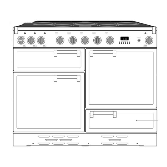
2. Cooker Overview ArtNo.025-0005 - Overview - 90 induction - 2 button clock & GO grill Fig.2-1 ºC ºC ArtNo.190-0002 - 110 Induction annotated GENERIC Your 110 induction cooker (Fig.2-1) has the following Fig.2-2 features: 5 induction cooking zones Control panel A separate grill or glide-out grill (depending on model) A conventional or multi-function oven (programmable, depending on model see Table 2-1) - Page 9 The very best pans have bases that are very slightly curved Model Programmable Oven up when cold (Fig.2-3). If you hold a ruler across the bottom Classic right-hand oven you will see a small gap in the middle. When they heat up the metal expands and lies at on the cooking surface.
-
Page 10: Child Lock
Residual Heat Indicator, H Auomatic Heat-up Time at Power Level 100% (min:sec) After use, a cooking zone will remain hot for a while as heat dissipates. When a cooking zone is switched o the residual 0:48 heat indicator symbol [H ], will appear in the display. This 2:24 shows that the cooking zone temperature is above 60 °C and may still cause burns. - Page 11 Low Temperature Setting, L1/L2 Maximum Operating Time Power Level Each cooking area is equipped with 2 low temperature settings: 2 hours L1 and L2 • L1 will maintain a temperature of about 40 °C – ideal for 6 hours gently melting butter or chocolate. 6 hours • L2 will maintain a temperature of about 90 °C –...
-
Page 12: The Grill / Glide-Out Grill
The Grill / Glide-out Grill Fig.2-9 CAUTION: This appliance is for cooking purposes only. It must not be used for other purposes, for example room heating. CAUTION: Accessible parts may be hot when the grill ArtNo.330-0003 - Grill pan w handle pulled forwards is in use. -
Page 13: The Ovens
The Ovens Function The clock must be set to the time of day before the To thaw small items in the oven without Defrost programmable oven will work. See the following section heat on ‘The Clock’ for instructions on setting the time of day. A full cooking function, even heat Fan oven throughout, great for baking... - Page 14 It is also possible to bake on two shelves at one time, Multi-function Oven Functions although they will need to be swapped over during the Rapid Response (Classic Deluxe & Professional Deluxe) cooking time, as the heat at the top of the oven is greater The Rapid Response setting enables you to preheat than at the base, when using this function.
-
Page 15: The Browning Element
Defrosting should not be carried out in a warm oven or when Fig.2-13 an adjoining oven is in use or still warm. Make sure that dairy foods, meat and poultry are completely defrosted before cooking. The Fan Oven Fan ovens circulate hot air continuously, which means faster, more even cooking. -
Page 16: The Clock
The Clock Fig.2-16 ArtNo.300-0004 2-button clock annotated 2-Button Clock Setting the Time of Day The 2-button LCD clock is shown in (Fig.2-16). When the clock is rst connected, the display ashes ( 0.00 ) and ( alternately. To set the time, turn and hold the Timer knob to the clock symbol [ ... - Page 17 The ‘stop time’ is displayed, followed by ‘AUTO’ . Set the oven ArtNo.301-0008 2BC Fig.2-23 to the cooking temperature you need. Turn the Timer knob to Stopping the oven 2 the ‘Auto’ setting. When your cooking is nished, the beeper sounds. Turn the Timer knob to the vertical [ ...
- Page 18 The 6-button Clock Fig.2-29 Setting the Time of Day The 6-button LCD clock is shown in Fig.2-29. When the clock is rst connected the display ashes ( 0.00 ) and ( alternately. ArtNo.302-0002 - 6BC annotated Press and hold both the [] and [] buttons down (Fig.2-30).
- Page 19 AUTO is Showing, You Want to Reset to Manual Fig.2-39 Fig.2-40 Cooking To return to manual cooking from any automatic setting, the ‘cook period’ must be cancelled. Press and hold the [] button and then press the [ –] button until the display reads ArtNo.302-0009 - Activating ( 0.00 ).
-
Page 20: Accessories
Accessories Fig.2-44 Oven Shelves – Left-hand (Main) Oven Flat shelf Shelf guard In addition to the at shelves your cooker is supplied with a drop shelf (Fig.2-44). The drop shelf increases the possibilities for oven shelf spacing. The oven shelves can be easily removed and re tted. Front Pull the shelf forward until the back of the shelf is stopped by the shelf stop bumps in the oven sides (Fig.2-45). -
Page 21: Storage
Storage Fig.2-52 The bottom drawer is for storing oven trays and other cooking utensils. ArtNo.340-0002 110 removing the drawer It can get very warm, so do not store anything in it that may melt or catch re. Never store ammable materials in the drawer. -
Page 22: Cooking Tips
3. Cooking Tips DocNo.030-0010 - Cooking tips - 110 induction GENERIC Hints on Using Your Induction Cooker General Oven Tips If you have not used an induction cooker before please be The wire shelves should always be pushed rmly to the back aware of the following: of the oven. -
Page 23: Cooking Table
4. Cooking Table DocNo.031-0004 - Cooking table - electric & fan single cavity The oven control settings and cooking times given in the table below are intended to be used Top (T) AS A GUIDE ONLY. Individual tastes may require the temperature to be altered to provide a preferred result. -
Page 24: Cleaning Your Cooker
5. Cleaning Your Cooker ArtNo.040-0005 - Cleaning - 110 induction GENERIC Isolate the electricity supply before carrying out any major Fig.5-1 cleaning. Allow the cooker to cool. NEVER use paint solvents, washing soda, caustic cleaners, biological powders, bleach, chlorine based bleach cleaners, coarse abrasives or salt. -
Page 25: Grills
Grills Fig.5-2 The grill pan and trivet should be washed in hot soapy water. Alternatively, the grill pan can be washed in a dishwasher. After grilling meats or any foods that soil, leave to soak for a few minutes immediately after use. Stubborn particles may be removed from the trivet using a nylon brush. -
Page 26: Control Panel And Doors
Control Panel and Doors Fig.5-7 Avoid using any abrasive cleaners, including cream cleaners. For best results, use a liquid detergent. The same cleaner can also be used on the doors. Alternatively, use a soft cloth wrung out in clean hot soapy water. You can use the same method for cleaning the control panel and knobs. -
Page 27: Cleaning Table
Cleaning Table Cleaners listed (Table 5-1) are available from supermarkets or electrical retailers as stated. For enamelled surfaces use a cleaner that is approved for use on vitreous enamel. Regular cleaning is recommended. For easier cleaning, wipe up any spillages immediately. Hotplate Part Finish... -
Page 28: Troubleshooting
6. Troubleshooting DocNo.050-0001 - Troubleshooting - Induction GENERIC Interference with and repairs to the hob MUST NOT The cooling fan be carried out by unquali ed persons. Do not try The induction hob incorporates a cooling fan. This to repair the hob as this may result in injury and cooling fan is active when either the grill or ovens damage to the hob. - Page 29 Food is cooking too slowly, too quickly, or burning Fig.6-1 Cooking times may di er from your previous oven. Check that you are using the recommended temperatures and shelf positions – see the oven ArtNo.324-0005 Oven light bulb cooking guide. Then adjust the settings according to your own individual tastes.
- Page 30 Taking care to protect your ngers with a glove in case Fig.6-3 the bulb should shatter, unscrew the old bulb. Screw in the new bulb clockwise and then screw the bulb cover back on. Turn on the electricity supply and check that the bulb now lights.
-
Page 31: Installation
INSTALLATION Check the appliance is electrically safe when you have nished. 7. Installation You will need the following equipment to complete the Dear Installer cooker installation satisfactorily: Before you start your installation, please complete the details • Multimeter (for electrical checks). below, so that, if your customer has a problem relating to your installation, they will be able to contact you easily. -
Page 32: Positioning The Cooker
INSTALLATION Check the appliance is electrically safe when you have nished. Positioning the Cooker ArtNo.090-0028 - 90 cooker min spacing GENERIC Fig.7-1 Fig.7-1 and Fig.7-2 show the minimum recommended 75 mm 75 mm distance from the cooker to nearby surfaces. 650 mm The cooker should not be placed on a base. -
Page 33: Repositioning The Cooker Following Connection
INSTALLATION Check the appliance is electrically safe when you have nished. Lowering the Two Rear Rollers Fig.7-5 To adjust the height of the rear of the cooker, rst t a 13 mm spanner or socket wrench onto the hexagonal adjusting nut (Fig.7-5). -
Page 34: Electrical Connection
INSTALLATION Check the appliance is electrically safe when you have nished. Electrical Connection Fig.7-8 The cooker must be installed by a quali ed electrician, in accordance with all relevant British Standards/Codes of Practice (in particular BS 7671), or with the relevant national and local regulations. -
Page 35: Final Fitting
INSTALLATION Check the appliance is electrically safe when you have nished. Final Fitting Fig.7-10 Fitting the Handles and Handrail (depending on model) Remove the 4 mm Allen screws from the doors (Fig.7-10). Fit the door handles and secure using the 4 mm screws. ArtNo.215-0026 - Handle gaskets fixed The handles should be above the xings. -
Page 36: Circuit Diagrams
8. Circuit Diagrams ArtNo.090-0003 - Circuit diagram - 110 induction GENERIC Circuit Diagram: Hob Earth On Terminal Block N(6) On Terminal Block N(4) INDUCTION UNIT DISPLAY w/br L(2) L(3) w/br INTERFACE On Terminal Block BOARD w/br w/br w/br The connections shown in the circuit diagram are for single-phase. The ratings are for 230 V 50 Hz. Code Description Code Colour Left-hand front element... -
Page 37: (Elan)
Circuit Diagram: Multi-function Oven (Elan) ArtNo.080-0049 110 Elan induction (oven) circuit diagram P095199 P033458 P033458 P028728 The connections shown in the circuit diagram are for single-phase. The ratings are for 230 V 50 Hz. Code Description Code Description Code Colour Grill front switch Clock Blue... -
Page 38: (Classic Deluxe & Professional Deluxe)
Circuit Diagram: Multi-function Oven (Classic Deluxe & Professional Deluxe) P038434 P033458 P033458 b b b The connections shown in the circuit diagram are for single-phase. The ratings are for 230 V 50 Hz. Code Description Code Description Code Colour Grill front switch Clock Blue Grill energy regulator... -
Page 39: Circuit Diagram: Conventional Oven
Circuit Diagram: Conventional Oven (Classic, Toledo & Professional+) P038482 P095199 P095199 b b b The connections shown in the circuit diagram are for single-phase. The ratings are for 230 V 50 Hz. Code Description Code Description Code Colour Grill front switch Right-hand fan oven element Blue Grill energy regulator... -
Page 40: Technical Data
9. Technical Data DocNo.100-0003 - Technical data - IN 110 - GENERIC INSTALLER: Please leave these instructions with the user. DATA BADGE LOCATION: Cooker back, serial number repeater badge below the oven door opening. COUNTRIES OF DESTINATION: GB, IE. Connections Electric 230 / 400 V 50 Hz Dimensions... - Page 41 Oven Efficiencies Left-hand Oven Right-hand Oven Ovens Multi-function Multi-function Conventional Forced Air Convection (with Rapid Response) Maximum output@ 230 V 50 Hz 2.5 kW 3.7 kW 2.2 kW 2.5 kW Energy efficiency class on a scale of A (more efficient) to G (less efficient) Energy consumption based on standard load 0.95 kWh 0.95 kWh...
- Page 42 Notes...
- Page 43 Gas Safe registered engineer for gas appliances or an approved electrician for electrical models. CONSUMER SERVICE For a competitive quote and to arrange for a Rangemaster approved If you have any product enquiries, or in the event of a problem engineer to attend, call Consumer Services on: 0870 7895107.
- Page 44 Registered in England and Wales. Registration No. 354715 Registered O ce: Juno Drive, Leamington Spa, Warwickshire, CV31 3RG Rangemaster continuously seeks improvements in speci cation, design and production of products and thus, alterations take place periodically. Whilst every e ort is made to produce up-to-date literature, this booklet should not be regarded as an infallible guide to...